


-
随着人工智能和互联网技术的快速发展,无人驾驶、无人机与智能机器人逐渐走进人们的日常生活中[1]。同步定位与地图构建(Simultaneous Localization and Mapping,SLAM)作为这些领域的重要技术之一,扮演着不可或缺的角色。
根据使用的观测传感器不同,SLAM主要分为视觉SLAM和激光SLAM。相机不能直接获取特征点的深度信息,并且容易受到相机运动和外界光线因素的影响[2]。激光雷达可以快速并稳健提供周围环境的高精度点云数据[3],提供周围环境的几何信息,不易受到环境影响。因此,相比于视觉SLAM,激光SLAM稳健性更高。
2016年,Google团队提出的Cartographer[4]可用于2D及3D激光SLAM,具有较高精度的室内定位与建图能力,而3D建图算法的实时性较差。2017年,LOAM[5]仅使用激光雷达传感器,采用一种基于曲率特征的前端里程计,保证了准确性与高效性,是激光SLAM中表现较好的算法之一,在旋转较快的场景稳健性不足。惯性测量单元(Inertial Measurement Unit,IMU)受零偏干扰,累积误差较大,但不易受外界干扰,使用积分方法可快速提供高频率的位置和姿态[6]。2018年,Shan等[7]在LOAM算法的基础上,采用松耦合的方式融合IMU数据,提出LeGO-LOAM,使用广度遍历优先算法提取地面点和非地面点,利用两步优化的帧间里程计以提高计算效率,并增加回环检测功能,降低累积误差。松耦合的融合方式对传感器数据利用不够充分,没有为传感器下一次定位提供帮助。2019年,Ye等[8]受VINS系统[9]的启发,采用紧耦合的融合方式融合IMU与激光雷达,修正IMU的零偏,实现了实时的激光里程计与建图方法LIO-mapping,简称为LIOM,但该算法的耗时较高。GPS[10]是一种全局定位传感器,可以获得全局信息。2020年,Shan等[11]提出LIO-SAM,使用紧耦合融合方式的同时,有效地加入GPS约束,可以很好地对抗快速移动和旋转等具有挑战性的大场景建图,在精度与运行时间上均有不俗表现,但是在极端环境下鲁棒性较低。长走廊、隧道等退化环境缺乏某个或多个自由度的几何信息,LIO-SAM存在系统精度低或算法失效的问题。常规环境中,前端里程计累积误差随场景变大而提高,LIO-SAM采用的基于欧氏距离回环检测方法存在漏检问题,无法消除前端里程计的累积误差。
针对上述问题,提出一种面向未知环境的紧耦合激光SLAM算法,在退化环境中更加稳健,回环检测的召回率更高。文中算法主要的创新之处在于以下两个方面:
1)提出一种退化环境中鲁棒的定位方法,计算LiDAR里程计雅克比矩阵,对比最小特征值低于阈值,判断环境的几何信息维度缺失,融合轮式里程计与IMU数据,补偿LiDAR里程计缺失的自由度,提升系统稳定性。
2)提出一种变阈值回环检测方法,合理剔除退化帧与邻近帧,扩大搜索阈值,构建变阈值回环搜索模型,采用不同配准方法分析对应阈值关键帧信息,提高回环检测召回率,修正历史帧位姿,保证建图的全局一致性。
-
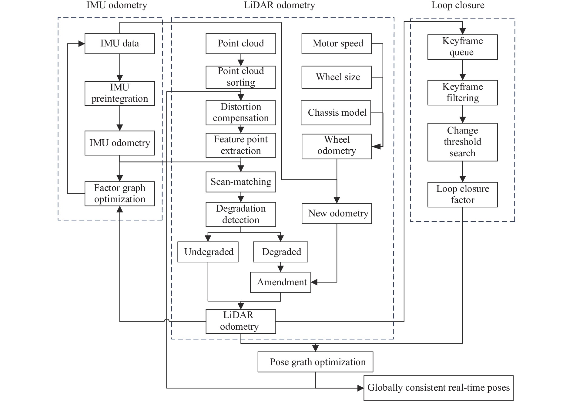
文中方法框架见图1,简单分为以下四个部分:

图 1 紧耦合激光SLAM算法框架
Figure 1. Framework of tightly coupled laser SLAM algorithm
1) IMU里程计模块:对IMU数据进行预积分,为LiDAR里程计提供高精度的先验信息,采用因子图优化方法,利用补偿后的LiDAR里程计修正IMU的零偏。
2) LiDAR里程计模块:利用IMU里程计的先验信息补偿点云数据的运动畸变,根据曲率大小提取特征点云,采用IMU里程计作为初值对特征点云配准。计算LiDAR里程计的雅克比矩阵,对比最小特征值低于阈值,判断环境的几何信息维度缺失,融合轮式里程计与IMU数据,补偿LiDAR里程计自由度。
3) 回环检测模块:利用LiDAR里程计构建关键帧队列,剔除队列中退化帧与邻近帧。构建变阈值回环搜索模型,采用不同配准方法分析对应阈值的关键帧信息,提高回环检测召回率。
4) 后优化模块:构建最小二乘模型,将LiDAR里程计和回环检测的约束作为残差,求解所有关键帧位姿的最优解,保证建图的全局一致性。
-
IMU预积分的核心思想是预积分结果与上一时刻系统状态无关[12],因此,IMU的零偏经过修正后,求解下一时刻结果不需要对前一时刻的系统状态重新积分。加速计与陀螺仪的真值$ a_k^ \wedge $、$ \omega _k^ \wedge $表示为:$a_k^ \wedge = {a_k} + {b_{{a_k}}} + {n_a}$、$ \omega _k^ \wedge = {\omega _k} + {b_{{\omega _k}}} + {n_\omega } $。其中$ a_k^ \wedge $、$ \omega _k^ \wedge $为加速计与陀螺仪的观测值,$ {b_{{a_k}}} $、$ {b_{{\omega _k}}} $为加速计与陀螺仪的零偏,$ {n_a} $、$ {n_\omega } $为加速计与陀螺仪的高斯噪声。
计算位姿、速度、旋转的预积分量:
$$ \alpha _{k + 1}^k = \mathop {\iint\limits_{{t_k}} {R_t^k}}\limits^{{t_{k + 1}}} (a_t^ \wedge - {b_{{a_t}}} - {n_a}){{\text{d}}^2}t $$ (1) $$ \beta _{k + 1}^k = \int\limits_{{t_k}}^{{t_{k + 1}}} {R_t^k(a - {b_{{a_t}}} - {n_a}){\text{d}}t} $$ (2) $$ \gamma _{k + 1}^k = \int_{{t_k}}^{{t_{k + 1}}} {q_t^k} \otimes \left[ {\begin{array}{*{20}{c}} 1 \\ {{{\omega _t^ \wedge \times \Delta t} \mathord{\left/ {\vphantom {{\omega _t^ \wedge \times \Delta t} 2}} \right. } 2}} \end{array}} \right]{\text{d}}t $$ (3) IMU频率较高,将所有时刻IMU零偏进行优化计算量过于庞大。可以假设短时间内IMU零偏保持不变,减少算力负担。计算位姿$ p $、速度$ v $、旋转$ q $:
$$ {p_{k + 1}} = {p_k} + {v_k} + {{\overline {a_k^ \wedge } \times \Delta {t^2}} \mathord{\left/ {\vphantom {{\overline {a_k^ \wedge } \times \Delta {t^2}} 2}} \right. } 2} $$ (4) $$ {v_{k + 1}} = {v_k} + \overline {a_k^ \wedge } \times \Delta t $$ (5) $$ {q_{k + 1}} = {q_k} \otimes \left[ {\begin{array}{*{20}{c}} 1 \\ {{{\overline {\omega _k^ \wedge } \times \Delta t} \mathord{\left/ {\vphantom {{\overline {\omega _k^ \wedge } \times \Delta t} 2}} \right. } 2}} \end{array}} \right] $$ (6) $$ \overline {a_k^ \wedge } {\text{ = }}{{\left[ {{q_k}(a_k^ \wedge - {b_{{a_k}}}) + {q_{k + 1}}(a_{k + 1}^ \wedge - {b_{{a_{k + 1}}}}) - 2g} \right]} \mathord{\left/ {\vphantom {{\left[ {{q_k}(a_k^ \wedge - {b_{{a_k}}}) + {q_{k + 1}}(a_{k + 1}^ \wedge - {b_{{a_{k + 1}}}}) - 2g} \right]} 2}} \right. } 2} $$ (7) $$ \overline {\omega _k^ \wedge } = {{({\omega _k} + {\omega _{k + 1}} - 2 \times {b_{{\omega _k}}})} \mathord{\left/ {\vphantom {{({\omega _k} + {\omega _{k + 1}} - 2 \times {b_{{\omega _k}}})} 2}} \right. } 2} $$ (8) -
环境几何信息维度检测是评估LiDAR里程计可靠性的关键能力。定位系统大多因不可观测失效[13],基于视觉的系统缺乏纹理和显著特征,激光雷达的前端里程计在长走廊等退化环境缺乏某个或多个维度的几何信息。
利用IMU里程计去除点云运动畸变,根据曲率提取面特征与线特征,计算点云曲率$ c $:
$$ c = \frac{1}{{\left| s \right| \cdot \left\| {X_{(k,j)}^{}} \right\|}}\left\| {\sum\limits_{j \in s,j \ne i} {(X_{(k,i)}^{} - X_{(k,j)}^{})} } \right\| $$ (9) 使用kd-tree获得每个线点$ {O_{\text{l}}} $临近的两个共线点$ {A_{\text{l}}} $、$ {B_{\text{l}}} $和每个面点$ {O_{\text{p}}} $邻近的三个不共线点$ {A_{\text{p}}} $、$ {B_{\text{p}}} $、$ {C_{\text{p}}} $,计算点到线的距离$ {d_{\text{l}}} $与点到面的距离$ {d_{\text{p}}} $之和作为残差$ e $:
$$ {d_{\text{l}}} = \frac{{\left| {\overrightarrow {{B_{\text{l}}}{O_{\text{l}}}} \times \overrightarrow {{A_{\text{l}}}{O_{\text{l}}}} } \right|}}{{\left| {\overrightarrow {{A_{\text{l}}}{B_{\text{l}}}} } \right|}} $$ (10) $$ {d_{\text{p}}} = \frac{{\left| {(\overrightarrow {{C_{\text{p}}}{B_{\text{p}}}} \times \overrightarrow {{A_{\text{p}}}{B_{\text{p}}}} ) \cdot \overrightarrow {{B_{\text{p}}}{O_{\text{p}}}} } \right|}}{{\left| {\overrightarrow {{C_{\text{p}}}{B_{\text{p}}}} \times \overrightarrow {{A_{\text{p}}}{B_{\text{p}}}} } \right|}} $$ (11) $$ e = \sum {{d_{\text{l}}} + \sum {{d_{\text{p}}}} } $$ (12) 目标函数对优化变量求导获得雅克比矩阵$ J $,对${J^{\rm T}}J$进行特征值分解。
$$ J = \frac{{\partial e}}{{\partial x}} $$ (13) $$ \left| {{J^{\text{T}}}J - \lambda E} \right| = 0 $$ (14) $$ {J^{\text{T}}}Jx = \lambda x $$ (15) 小于阈值的特征值对应特征向量方向的几何信息缺失,该方向LiDAR里程计发生退化。特征值大于阈值,计算相邻帧位姿:
$$ {J^{\text{T}}}J\Delta x = - {J^{\text{T}}}e $$ (16) -
为减轻回环检测与后端优化的计算负担,根据LiDAR里程计选取关键帧。关键帧的选取指标通常分为时间指标、距离指标、共视特征点指标[14],文中采用的观测传感器为激光雷达,共视特征点较多,使用较为合理的距离指标选取关键帧。
求解几何信息缺失的闭环约束易丢失自由度,去除发生退化的关键帧。为避免误检邻近帧,并解决机器人停留问题,剔除距离当前帧帧数差值较小的关键帧。
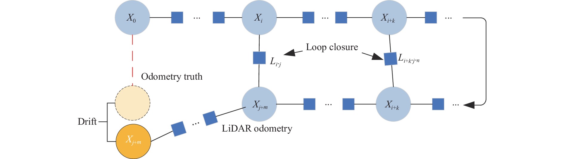
如图2所示,LiDAR里程计存在累积误差,LiDAR里程计中的漂移可能大于搜索阈值,导致错过检测到闭合回路的机会。

图 2 里程计累积误差
Figure 2. Cumulative error of the odometer
为提高回环检测召回率,如图3所示,构建变阈值回环搜索模型,采用不同配准方法分析对应阈值关键帧信息。使用最大检测阈值$ {T_0} $筛选出备选关键帧,为保证阈值设置合理性,将相邻帧相对位姿方差分为退化方差$ {v_{{\text{de}}}} $与非退化方差$ {v_{{\text{no}}}} $。

图 3 变阈值回环检测
Figure 3. Loop detection of variable threshold
设置不同的回环检测阈值$ {T_1} $、$ {T_2} $、$ {T_3} $,使用对应的求解方法求得回环处的相对位姿,并将ICP得分小于阈值的关键帧作为备选约束。
其中$ {T_0}:\left[ {0,{F_{\text{m}}}} \right) $、$ {T_1}:\left[ {0,{F_{\text{c}}} - {F_{\text{v}}}} \right) $、$ {T_2}:[ {F_{\text{c}}} - {F_{\text{v}}},{F_{\text{c}}} + {F_{\text{v}}} ] $、$ {T_3}:\left( {{F_{\text{c}}} + {F_{\text{v}}},{F_{\text{m}}}} \right] $、$ {F_{\text{v}}} = {n_{{\text{de}}}} \cdot {v_{{\text{de}}}} + {n_{{\text{no}}}} \cdot {v_{{\text{no}}}} $,$ {F_{\text{c}}} $为可检测到的回环距离,$ {F_{\text{v}}} $为备选帧到当前帧的方差,$ {n_{{\text{de}}}} $、$ {n_{{\text{no}}}} $为备选帧到当前帧中退化帧数与非退化帧数。
当有新的备选约束进入,等待固定时间是否有新的备选约束[15],选取最小欧氏距离的备选约束作为回环约束,添加到位姿图中。
-
位姿图优化旨在消除LiDAR里程计的累积误差,保证全局一致性。将每一关键帧位姿作为待优化变量,LiDAR里程计中相邻关键帧之间的相对位姿和回环作为约束,构建位姿图模型,即求解最小二乘问题,如公式(17)所示:
$$ \min \frac{1}{2}\sum\limits_{i,j \in \varepsilon } {e_{ij}^{\text{T}}\sum\nolimits_{ij}^{ - 1} {{e_{ij}}} } $$ (17) 由于目标函数为非线性函数,使用列文伯格马夸尔特优化方法进行求解,获得每个关键帧的最优位姿,然后利用优化后的位姿对点云地图进行修正,保证地图的全局一致性。
-
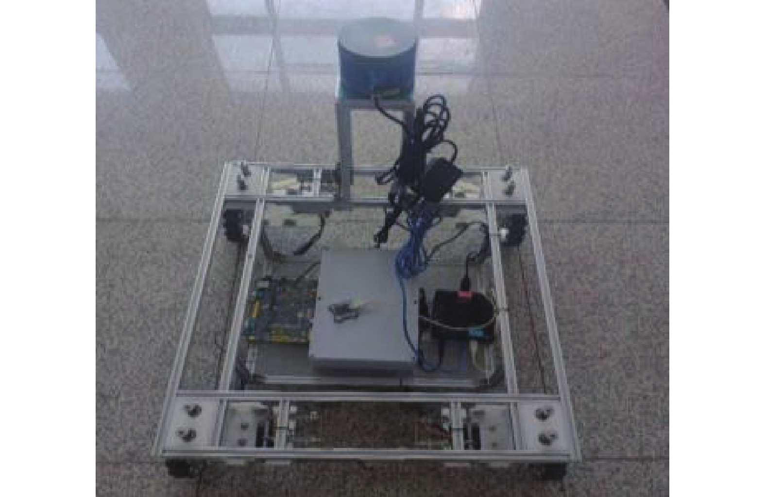
为测试文中方法的性能,采用如图4所示的轮式移动机器人进行测试。文中机器人搭载9轴IMU、大疆M3508电机、C620电调和RS-LiDAR-16激光雷达,水平视角为360°,垂直视角为30°,点云输出频率为10 Hz,有效距离0.4~150 m,精度小于3 cm。移动机器人底盘配有四个麦克纳姆轮,可实现全向移动,搭载装有Ubuntu16.04系统的NUC8 i5 BEK1工控机上运行,算法主体基于ROS平台进行开发。

图 4 实验机器人平台
Figure 4. Experimental robot platform
-
退化测试场景为校园中的长走廊,见图5,长为76.78 m、宽为1.85 m,两侧是大面积的白墙,场景重复度高,运动方向几何特征较少。为防止扫描到室内环境破坏退化场景,在录制数据集时关闭了所有办公室的门窗,该走廊符合文中所讨论的退化场景特点。

图 5 长走廊环境
Figure 5. Long corridor environment
针对该数据集,使用了A-LOAM (LiDAR)、LIO-SAM (LiDAR+IMU)和文中方法算法(LiDAR+IMU+轮速计)进行了测试,采用文献[16]中“场景还原度”为评估指标,验证文中方法的有效性。场景还原度为$ \gamma $,其计算方式为:
$$ \gamma {\text{ = }}\frac{{{l_{\text{m}}}}}{{{l_{\text{t}}}}} \times 100{\text{%}} $$ (18) 式中:$ {l_{\text{m}}} $为最后建成的点云地图里场景长度的测量值;$ {l_{\text{t}}} $为实际走廊长度的手工测量值。
-
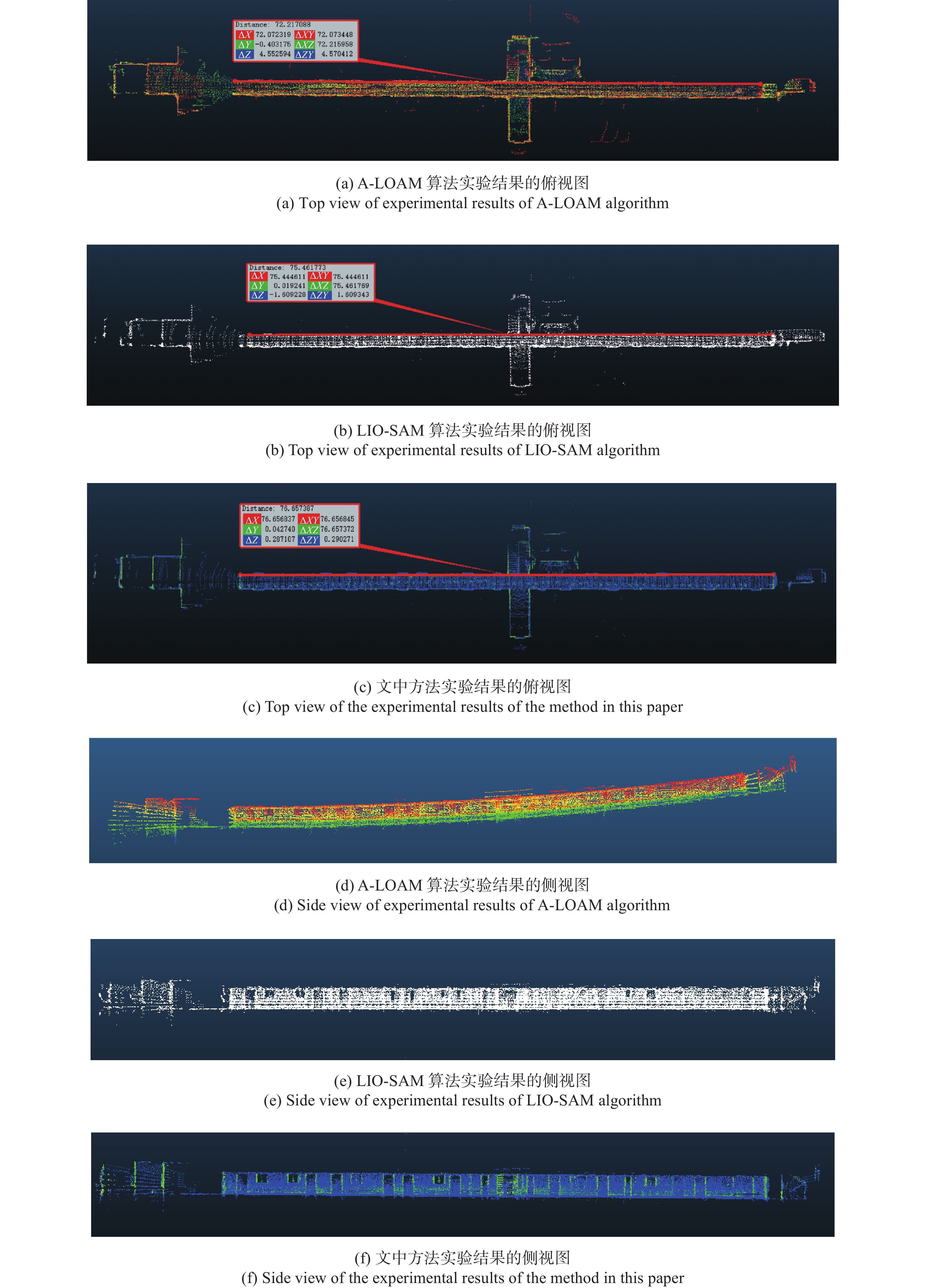
图6展示了A-LOAM算法、LIO-SAM算法和文中方法建图实验结果的俯视图和侧视图。为鲜明对比三种算法的建图精度,在长走廊中部楼梯处对齐三个地图。如图6(a)~(c)所示,A-LOAM、LIO-SAM和文中方法的建图长度分别为72.22、75.44、76.66 m,由CloudCompare软件测得。如图6(d)~(f)所示,A-LOAM建图结果的Z轴产生了严重漂移,LIO-SAM与文中方法的Z轴无明显漂移。

图 6 算法对比实验
Figure 6. Algorithm comparison experiment
表1为A-LOAM、LIO-SAM与文中方法的实验结果,场景还原度由公式(18)与测试场景走廊长度求出,长走廊中不易精确获取里程计真值,里程计漂移由建图长度推算出。文中方法在长走廊退化场景中场景还原度达到99.71%,里程计漂移降低至0.12 m,较A-LOAM、LIO-SAM分别降低了91.04%和97.37%。
表 1 算法性能对比
Table 1. Algorithm performance comparision
Item Proposed LIO-SAM A-LOAM Odometry drift/m 0.12 1.34 4.56 Scene restoration degree 99.71% 98.25% 94.06% -
如表2所示,SLAM的回环检测性能主要使用准确率(precision)和召回率(recall)[17]这两个参数评估。准确率表示所有算法检测到的回环中真实回环的概率,召回率表示所有真实回环中被正确检测到的概率,计算方式分别为:
表 2 回环检测评估参数
Table 2. Evaluation parameters of loop detaction
Algorithm
/FactLoop closure Not loop closure Loop closure TP FP Not loop closure FN TN $$ precision = \frac{{T P}}{{T P + F P}} $$ (19) $$ recall = \frac{{T P}}{{T P + T N}} $$ (20) -
文中回环检测实验采用自制数据集,A-LOAM算法无回环检测模块,文中方法与LIO-SAM的回环检测实验结果如表3所示。通过控制建图范围调节算法前端里程计漂移大小,分别选取三个漂移阈值的数据集测试LIO-SAM算法与文中方法的回环检测性能,为避免偶然性,每个阈值选取20个数据集进行测试。测试结果表明,随着前端里程计漂移的不断增加,LIO-SAM算法回环检测的召回率由100%逐渐降低至20%。在满足回环检测准确率为100%的条件下,文中方法回环检测的召回率受里程计漂移影响较小,相对LIO-SAM算法平均提高35%。
表 3 回环检测结果对比
Table 3. Comparison of loop detection results
Drift/m Proposed LIO-SAM precision recall precision recall 0-5 20/20 20/20 20/20 20/20 5-10 20/20 20/20 14/14 14/20 10-15 19/19 19/20 4/4 4/20 -
针对快速旋转场景的测试如图7所示,图7(a)~(f)为六个由角速度递增的旋转数据集分别采用A-LOAM、LIO-SAM和文中方法实时建图的结果。随着旋转速度的提升,A-LOAM算法的前端里程计收敛效果下降,产生的漂移递增,建图结果中重影更加明显。LIO-SAM和文中方法较好地克服了旋转速度提升带来的影响,建图结果无明显重影,较好地还原了场景的几何信息。在快速旋转场景,利用IMU预积分结果作为初值,提升系统稳健性。

图 7 快速旋转场景实验结果对比
Figure 7. Comparison of experimental results of fast rotating scene
-
在文中的七个数据集上,A-LOAM、LIO-SAM和文中方法的单帧平均运行时间如表4所示。
表 4 单帧运行时间对比
Table 4. Comparison of single frame run time
Dataset A-LOAM
/msLIO-SAM
/msProposed
/msLong corridor 22.4 12.2 13.4 Fast rotating scene I 139.2 67.6 67.8 Fast rotating scene II 99.6 58.3 58.7 Fast rotating scene III 114.7 57.1 57.6 Fast rotating scene IV 92.0 58.1 58.5 Fast rotating scene V 198.2 63.6 64.0 Fast rotating scene VI 294.4 57.8 58.1 在所有测试过程中,激光雷达数据的输出频率为10 Hz时,如果运行时需要超过100 ms,那么一些激光雷达帧就会丢失。与LOAM相比,LIO-SAM与文中方法每帧平均运行时间要少得多,更适合于部署在低功耗的嵌入式系统上。安装文中方法的移动机器人在各类数据集中均可稳定运行,说明文中方法满足实时性需求。
-
文中针对传统激光SLAM在长走廊、隧道等退化环境下系统精度低或算法失效,且存在常规环境下回环检测稳健性差等问题,提出了一种面向未知环境的紧耦合激光SLAM方法,采用紧耦合融合方式,利用LiDAR里程计修正IMU零偏,使用IMU数据提供高精度先验信息。通过计算LiDAR里程计雅克比矩阵,实时检测环境退化情况,融合轮式里程计与IMU数据,提升系统稳定性。提出一种基于欧氏距离改进的变阈值回环检测方法,提高回环检测召回率,保证了地图的全局一致性。文中方法在长走廊环境中场景还原度达到99.71%,在满足回环检测准确率为100%的条件下,召回率达到98.3%,较LIO-SAM算法平均提高35%。解决了紧耦合系统在退化环境中定位与建图稳健性差的问题,改善了室外大场景回环检测召回率的现象。
Tightly coupled LiDAR SLAM method for unknown environment
-
摘要: 针对传统激光SLAM在长走廊、隧道等退化环境下系统精度低或算法失效,且存在常规环境下回环检测稳健性差等问题,提出一种面向未知环境的紧耦合激光SLAM方法。首先,采用紧耦合框架,融合LiDAR与IMU信息,修正IMU零偏,为LiDAR里程计提供高精度先验信息;其次,计算LiDAR里程计雅克比矩阵,实时检测环境几何信息维度,融合轮式里程计与IMU数据,补偿LiDAR里程计自由度;最后,构建变阈值回环搜索模型,采用不同配准方法分析对应阈值的关键帧信息,提高回环检测召回率。长走廊环境中,所提方法定位误差较A-LOAM、LIO-SAM分别降低了91.04%和97.37%;常规环境中,在满足回环检测准确率为100%的条件下,所提方法召回率较LIO-SAM提高了35%。实验结果表明,所提方法具有较高的鲁棒性与定位精度。Abstract:
Objective Three-dimensional lidar is widely used in simultaneous localization and mapping (SLAM) research due to its accurate and reliable measurement performance, and has achieved fruitful results. However, in the scene where the geometric features such as long corridors and tunnels are not rich enough, the point cloud registration will have an additional degree of freedom in one direction, and the laser SLAM based on the point cloud information will degenerate, resulting in the failure of robot positioning and mapping, which will lead to the failure of subsequent navigation tasks. That is to say, when moving along a long corridor, the laser point cloud obtained is the same, which makes the matching algorithm unable to accurately estimate the motion in this direction. And in the conventional environment, the accumulated error of the front-end odometer increases with the increase of the scene. The loopback detection method based on the Euclidean distance of the traditional laser SLAM algorithm has the problem of missing detection and cannot eliminate the accumulated error of the front-end odometer. For this reason, a close-coupled laser SLAM method for an unknown environment is proposed in this paper. Methods First of all, a close-coupled framework (Fig.1) is used to fuse LiDAR and IMU information, correct IMU bias, and provide high-precision prior information for the LiDAR odometer. Secondly, the LiDAR odometer Jacobi matrix is calculated, the environmental geometric information dimension is detected in real-time, the wheel odometer and IMU data is integrated, and the freedom of LiDAR odometer is compensated. Finally, in view of the loopback detection method based on Euclidean distance that has missed detection due to the accumulated error of the odometer (Fig.2), a variable-threshold loopback search model is constructed, and the corresponding threshold key frame information is analyzed by different registration methods to improve the loopback detection recall rate (Fig.3). Results and Discussions A-LOAM, LIO-SAM and the method in this paper are used to test in a 76.78 m long and 1.85 m wide corridor respectively. The corridor is flanked by large white walls, with high scene repetition and fewer geometric features in the direction of motion. In the long corridor degradation scenario, the scene restoration degree of the method in this paper reaches 99.71%, and the odometer drift is reduced to 0.12 m, which is 91.04% and 97.37% lower than A-LOAM and LIO-SAM, respectively (Tab.1). In addition, the data sets with three drift thresholds are selected, and 20 data sets are selected for each threshold to test the loopback detection performance. Under the condition that the accuracy of loopback detection is 100%, the recall rate of loopback detection is 98.3%, which is 35% higher than that of the LIO-SAM algorithm on average (Tab.3). Conclusions In this study, a close-coupled laser SLAM method for an unknown environment is proposed. This method uses a tight coupling framework to improve the efficiency of sensor information utilization, and can detect the geometric information dimension of the environment in real-time. In the environment of fast-rotating scenes and missing geometric information, it can still achieve high-precision positioning and mapping. A variable threshold loopback search model is builded, which can maintain a high loopback detection recall rate in large scenes. The position and posture of historical frames are corrected, and the global consistency of the map is ensured. The proposed method is proved to be robust and accurate by many scene experiments. -
Key words:
- LiDAR SLAM /
- long corridors /
- degraded environment /
- tightly coupled /
- loop detection
-
表 1 算法性能对比
Table 1. Algorithm performance comparision
Item Proposed LIO-SAM A-LOAM Odometry drift/m 0.12 1.34 4.56 Scene restoration degree 99.71% 98.25% 94.06%  下载: 导出CSV
表 2 回环检测评估参数
Table 2. Evaluation parameters of loop detaction
Algorithm
/FactLoop closure Not loop closure Loop closure TP FP Not loop closure FN TN
下载: 导出CSV
表 3 回环检测结果对比
Table 3. Comparison of loop detection results
Drift/m Proposed LIO-SAM precision recall precision recall 0-5 20/20 20/20 20/20 20/20 5-10 20/20 20/20 14/14 14/20 10-15 19/19 19/20 4/4 4/20
下载: 导出CSV
表 4 单帧运行时间对比
Table 4. Comparison of single frame run time
Dataset A-LOAM
/msLIO-SAM
/msProposed
/msLong corridor 22.4 12.2 13.4 Fast rotating scene I 139.2 67.6 67.8 Fast rotating scene II 99.6 58.3 58.7 Fast rotating scene III 114.7 57.1 57.6 Fast rotating scene IV 92.0 58.1 58.5 Fast rotating scene V 198.2 63.6 64.0 Fast rotating scene VI 294.4 57.8 58.1
下载: 导出CSV
-
[1] 柴家贺, 董明利, 孙鹏, 等. 工业相机自热引起像点漂移模型与补偿方法[J]. 红外与激光工程, 2021, 50(6): 11. doi: 10.3788/IRLA20200494. Chai J H, Dong M L, Sun P, et al. Model and compensation method of image point drift caused by self-heating of industrial camera [J]. Infrared and Laser Engineering, 2021, 50(6): 20200494. (in Chinese) doi: 10.3788/IRLA20200494 [2] 朱子健, 张贵阳, 杨明, 等. 基于法化矩阵降维的多相机快速光束法平差算法[J]. 红外与激光工程, 2021, 50(2): 20200156. doi:10.3788/IRLA20 200156. Zhu Z J, Zhang G Y, Yang M, et al. Multi-camera fast bundle adjustment algorithm based on normalized matrix dimensionality reduction [J]. Infrared and Laser Engineering, 2021, 50(2): 20200156. (in Chinese) doi: 10.3788/IRLA20200156 [3] 杜瑞建, 葛宝臻, 陈雷. 多视高分辨率纹理图像与双目三维点云的映射方法[J]. 中国光学, 2020, 13(5): 1055-1064. doi:10.37188/CO.2020-0 034 Du R J, Ge B Z, Chen L. Texture mapping of multi-view high-resolution images and binocular 3D point clouds [J]. Chinese Optics, 2020, 13(5): 1055-1064. (in Chinese) doi: 10.37188/CO.2020-0034 [4] Hess W, Kohler D, Rapp H, et al. Real-time loop closure in 2D LIDAR SLAM [C]//2016 IEEE International Conference on Robotics and Automation (ICRA). IEEE, 2016: 1271-1278. [5] Zhang J, Singh S. Low-drift and real-time lidar odometry and mapping [J]. Autonomous Robot, 2017, 41: 401-416. doi: 10.1007/s10514-016-9548-2 [6] Zhao Yaozhong, Xian Jinlong, Gao Wei. Research on a real-time odometry system integrating vision, LiDAR and IMU for autonomous driving [J]. Infrared and Laser Engineering, 2022, 52(8): 20210651. (in Chinese) doi: 10.3788/IRLA20210651 [7] Shan T X, Englot B. LeGO-LOAM: Lightweight and ground optimized lidar odometry and mapping on variable terrain[C]//IEEE/RSJ International Conference on Intelligent Robots and Systems. Piscataway, USA. New York: IEEE, 2018: 4758-4765. [8] Ye H, Chen Y, Liu M. Tightly coupled 3D lidar inertial odometry and mapping[C]//2019 International Conference on Robotics and Automation (ICRA), 2019: 3144–3150. [9] Qin T, Li P, Shen S. VINS-Mono: a robust and versatile monocular visual-inertial state estimator [J]. IEEE Transactions on Robotics, 2018, 34(4): 1004-1020. doi: 10.1109/TRO.2018.2853729 [10] 李劲澎, 姜挺, 龚志辉, 等. 稳健李代数旋转平均用于GPS辅助无人机影像三维重建[J]. 光学精密工程, 2017, 25(6): 1607-1618. doi:10.3788/OPE.20 172506.1607 Li J P, Jiang T, Gong Z H, et al. GPS-supported 3D reconstruction of UAV images based on robust Lie-algebraic rotation averaging [J]. Optics and Precision Engineering, 2017, 25(6): 1607-1618. (in Chinese) doi: 10.3788/OPE.20172506.1607 [11] Shan T, Englot B, Meyers D, et al. LIO-SAM: tightly-coupled lidar inertial odometry via smoothing and mapping[C]//Proceedings of 2020 IEEE/RSJ International Conference on Intelligent Robots and Systems (IROS), 2020: 5135-5142. [12] Forster C, Carlone L, Dellaert F, et al. IMU Preintegration on manifold for efficient visual-inertial maximum-a-posteriori estimation [C]//Robotics: Science and Systems XI, Rome, Italy, 2015. [13] 陈晓冬, 艾大航, 张佳琛, 等. Gabor滤波融合卷积神经网络的路面裂缝检测方法[J]. 中国光学, 2020, 13(6): 1293-1301. doi:10.37188/CO.2020-0 041 Chen X D, Ai D H, Zhang J S, et al. Gabor filter fusion network for pavement crack detection [J]. Chinese Optics, 2020, 13(6): 1293-1301. (in Chinese) doi: 10.37188/CO.2020-0041 [14] 尹芳, 吴云. 空间非合作旋转目标的模型重建与位姿优化[J]. 光学精密工程, 2019, 27(8): 1854- 1862. doi: 10.3788/OPE.20192708.1854 Yin F, Wu Y. Model reconstruction a and pose optimization of non-cooperative rotating space target [J]. Optics and Precision Engineering, 2019, 27(8): 1854-1862. (in Chinese) doi: 10.3788/OPE.20192708.1854 [15] Frosi M, Matteucci M. ART-SLAM: accurate real-time 6 DoF LiDAR SLAM [J]. IEEE Robotics and Automation Letters, 2021, 7(2): 2692-2699. doi: 10.48550/arXiv.2109.05483 [16] 许宇伟, 颜文旭, 吴炜, 等. 相似场景下基于局部地图的激光SLAM前端算法改进[J]. 机器人, 2022, 44(2): 176-185. doi:10.13973/j.cnki.rob ot.20 0541 Xu Y W, Yan W X, Wu W, et al. Improvement of LiDAR SLAM front-end algorithm based on local map in similar scenes [J]. Robot, 2022, 44(2): 176-185. (in Chinese) doi: 10.13973/j.cnki.robot.200541 [17] Capdevila M, Márquez Flórez, Oscar W. A Communication perspective on automatic text categorization [J]. IEEE Transactions on Knowledge & Data Engineering, 2009, 21(7): 1027-1041. doi: 10.1109/TKDE.2009.22 -

 点击查看大图
图(7) / 表(4)
计量
- 文章访问数: 110
- HTML全文浏览量: 22
- PDF下载量: 34
- 被引次数: 0

