


-
回音壁模式(Whispering Gallery Mode, WGM)因其质量系数高、模型体积小而被广泛用于高灵敏度的传感检测[1-3]。以毛细管为代表的微管腔作为传感器件具有试剂样品消耗量小,比表面积大可增强分析灵敏度,传质速率快可缩短分析时间等特点[4-6]。
由于WGM系统中微管腔的高度对称性,光子被很好地限制在腔内。因此,回音壁模式不容易被有效地激发或从外部收集。为了解决这个问题,需要引入耦合器将来自激光器的光耦合到腔体中,然后将腔体中的一些光耦合到光学信号输入设备中,例如光电探测器或光谱仪等。用于实现光与谐振腔之间耦合的最常见方法是使用近场耦合器的倏逝波耦合[7]。常用于微管腔回音壁模式激发的近场耦合器件主要有棱镜[8]和光纤锥[9-11] ,但棱镜耦合系统的器件大,且系统较复杂,不利于集成小型化。锥形光纤用于耦合需要拉锥1~3 μm,非常脆弱,鲁棒性较差。为了解决这些问题,研究人员提出了光纤端面耦合器[12],并在实验中得到实现。光纤端面耦合激发WGM首先由Vladimir S. Ilchenko等人[13]提出,他们通过光纤端面与微球谐振器耦合激发了高Q回音壁模式。随后,Hanumegowda等人[14]成功将光纤端面与微球耦合谐振结构应用于生物传感,并对蛋白水解活性进行了检测[15]。2022年,Liu等人[16]在端面耦合的基础上,提出了梯形角光纤端面与双微球耦合谐振激发WGM,进一步研究了端面耦合的耦合特性。
光纤端面耦合器不仅减小了整个耦合系统的体积,而且克服了在棱镜耦合装置需要调整光学聚焦的困难。光纤作为光波导器件可以直接进行光输入与光输出,大大简化了耦合系统。然而,目前光纤端面主要用于高Q值微球腔WGM的耦合激励,而为了检测微管内壁微环境状态,需要激发微管腔WGM。相较于微球腔,微管腔具有中空心结构,WGM的特征方程分析更加复杂,与微球耦合谐振分析有所不同。因此,深入研究和分析光纤端面耦合器对微管腔WGM的激发作用具有重要意义。
文中提出了一种用于激发毛细管微反应器回音壁谐振的光纤楔形端面耦合器,建立光纤楔形端面与微管腔的耦合谐振模型,分析光纤楔形端面与微管腔的耦合谐振光谱特征。通过时域有限差分法进行数值模拟,仿真计算光纤楔形端面耦合器抛磨角度与微管腔结构参数的相位匹配关系,并制备光纤楔形端面耦合器,进行WGM谐振态的实验测试验证。
-
图1所示为光纤楔形端面与微管腔的耦合谐振原理图,耦合谐振结构包括微管腔和两个光纤楔形端面耦合器(输入耦合器1和输出耦合器2)。光纤楔形端面耦合器的抛磨角为θ,来自宽带光源的光被发射到光纤楔形端面形成倏逝场。楔形端面形成倏逝场需要选择合适的抛磨角θ使得入射光满足全反射条件:
$$ \theta \gt {\theta _c} = {\rm{arcsin}}\left( {{n_0}/{n_{{\rm{core}}}}} \right) $$ (1) 式中:θc为形成入射光全反射的临界入射角;n0为空气折射率;ncore为光纤纤芯的折射率。

图 1 光纤楔形端面与微管腔的耦合谐振
Figure 1. The coupling resonance of fiber wedge end face and micro-tubular cavity
当微管处于倏逝场的核心区域时,楔形光纤的波导模式与微管腔体的WGM发生共振,进行能量交换。楔形端面光纤的抛磨角度和端面与毛细管微腔之间的距离会直接影响回音壁谐振耦合的耦合效率。理想情况下的耦合状态应满足相位匹配,即存在耦合临界角为:
$$ \theta = {\text{ }}{\rm{arcsin}}({n_{{\rm{WGM}}}}/{n_{fiber}}) $$ (2) 式中:nWGM是WGM方位传播的有效折射率;nfiber是光纤中导波的有效折射率。当抛磨角度大于入射光全反射临界角后,楔形端面可以产生倏逝场进行耦合。抛磨角越接近耦合临界角,耦合效率越高。当抛磨角度超过耦合临界角,耦合效率会急剧降低。
对于微管结构,WGM的有效折射率nWGM可定义为[17]:
$$ {n_{{\rm{WGM}}}} = {n_1}{\eta _1} + {n_3}{\eta _3} + {n_2}(1 - {\eta _1} - {\eta _3}) $$ (3) 式中:n1、n2、n3分别为微管管芯、微管与微管外部的折射率;η1、η2、η3分别为微管管芯、微管、微管外部的电磁场能量分布系数。电磁场能量分布系数ηi(i=1,2,3)表示为:
$$ {\eta _i} = \frac{{{\gamma _i}}}{\gamma } = \frac{{{{ \displaystyle \int\limits_{{{\text{V}}_i}} {{\varepsilon _0}n{{(r)}^2}\left| {{E_{m,l}}} \right|} }^2}{\rm{d}}r}}{{{{ \displaystyle \int\limits_{\text{V}} {{\varepsilon _0}n{{(r)}^2}\left| {{E_{m,l}}} \right|} }^2}{\rm{d}}r}} $$ (4) 式中:ε0为真空介电常数;E为电场分布;r为相应的微管结构半径(内径、外径)参数;V是整个空间,Vi(i = 1,2,3)分别是微管的内部、微管和外部区域。γi(i = 1,2,3)分别是Vi(i = 1,2,3)区域的电场能量。
对于楔形端面光纤中导波的有效折射率,由于纤芯中的导波在反射后不再存在,所以nfiber的精确计算是一项非艰巨的任务,意味着要明确计算截断区域的倏逝场。而基于模式传播常数,可以得到近似表达式:
$$ {n_{fiber}} \approx {n_5}[1 + \Delta {({{w}}/{{W}})^2}] $$ (5) 式中:Δ=(n4−n5)/n5为相对指数差;w为归一化横向衰减常数;W为归一化频率;n4、n5分别为光纤纤芯与包层的折射率。
另一方面,耦合距离也是直接影响谐振耦合效率的重要参数。楔形端面与毛细管微腔之间的距离需要满足:
$$ d \leqslant {d_c} = \frac{\lambda }{{2\pi \sqrt {n_2^2{{\sin }^2}\theta - n_3^2} }} $$ (6) 式中:λ为回音壁摸式在真空中的波长;dc为倏逝波的趋肤深度。耦合间距小于dc才能形成有效的回音壁模式耦合。随着耦合距离逐渐减小,耦合效率会逐渐增大,且存临界耦合间距使耦合效率达到最大。越靠近临界耦合间距,耦合效率越高。临界耦合距离的大小为入射光亚波长量级,并且受耦合入射角和光学微腔腔内光功率衰减影响,耦合入射角越小,腔内衰减约小,临界耦合距离就越大,临界耦合越容易实现。
考虑到微管腔与楔形端面近距离的接触容易引起二者表面的磨损,耦合效率会受到较大影响。为了不损害二者表面光滑度,在楔形端面光纤抛磨角的选择上不宜过大,以获得相对更大的临界耦合间距,使得在实际应用中,可以尽可能地接近临界耦合间距,从而获得更高的耦合效率。
-
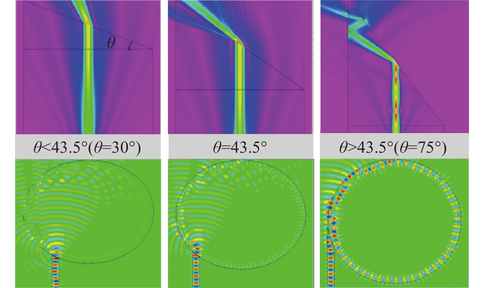
使用RSoft软件对光纤楔形端面与微管腔的耦合进行模拟仿真,以验证谐振状态,分析光谱特征。首先,模拟不同抛磨角度θ下光纤楔形端面上的光场分布,以分析楔形端面区域光的传播,验证耦合谐振状态。设置光纤纤芯直径为8.3 μm,折射率ncore=1.4505;光纤包层直径为125 μm,折射率为1.445 3;空气折射率n0=1;自由空间波长为1 550 nm。带入仿真设置数值可以得到θc=43.5°。对抛磨角小于入射临界角、等于入射临界角以及大于入射临界角的情况进行模拟仿真,设置楔形端面抛磨角分别为30°、43.5°、75°。图2所示为三种抛磨角θ楔形端面的光场分布情况和相应抛磨角楔形端面光纤与微管腔(内径8 μm,外径9 μm,折射率1.4446)的耦合状态。

图 2 不同抛角θ楔形端面光纤的光场分布与耦合谐振状态
Figure 2. Optical field distribution and coupled resonance states of wedge-terminated fibers with different throw angles θ
当抛磨角θ满足全反射条件时,楔形端面和空气接触面将产生倏逝场。调节微管腔至倏逝场的核心区域位置,通过调整耦合间距,可以将光有效耦入微管腔。当光在微管中传输满足全反射条件时,即可沿微管腔侧壁经多次反射后耦合进入另一根光纤。微管腔中的光得到相干增强并形成稳定的传输模式,即形成回音壁谐振。
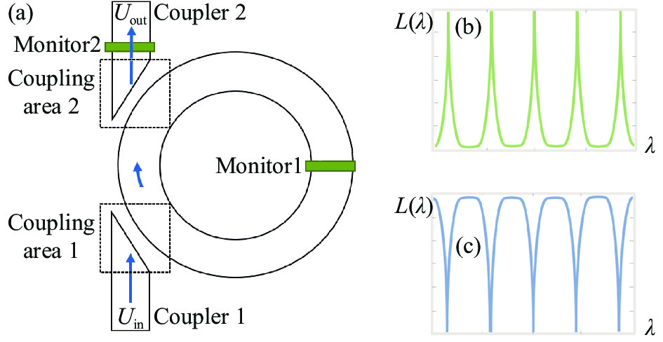
对微管腔耦合谐振激发的WGM进行分析。图3(a)为光纤楔形端面与微毛细管耦合结构的仿真设计图。这里分析理想状态的传输情况,忽略波导传输等损耗。复振幅为Uin的光波从光纤输入端入射,并在光纤中形成稳定的导波模式。当光传输至楔形端面与毛细管微腔的耦合区域时,部分导波模式通过全反射形成的倏逝波耦合进入微管腔中,耦合系数记作iκ,进入微管中的光光场复振幅为iκUin, 耦合过程中模式发生了π/2的相位延迟。耦合进微管腔的光波分量iκUin将在微管腔中循环传输,,且最终形成模式的复振幅为:

图 3 (a)光纤楔形端面与微毛细管耦合结构的仿真设计;(b)洛伦兹型尖峰特征光谱;(c)洛伦兹型凹谷特征光谱。
Figure 3. (a) Simulation design of coupling structure of fiber wedged end face and micro capillary tube; (b) Characteristic spectrum of Lorentz peak; (c) Characteristic spectrum of Lorentz dip
$$ {U_0}{{ = i}}\kappa {{}} \left( \sum {{t^{m - 1}}{a^m}{{\rm e}^{im\delta }}} \right){{ }}{U_{{\rm{in}}}} $$ (7) 式中:m为光波在微管腔中的循环次数,m无穷大时表示形成稳态模式;ɑ和δ分别为光波在微环腔中循环一周的传输系数和相位延迟,其中ɑ=e−σL,σ为光波在微管腔中传输的损耗系数。δ=2πnL/λ,L和n分别为微环腔的周长和传输模式的有效折射率,λ为光波在真空中的波长。当输入光波的波长λ可以使相位延迟δ为2π的整数倍时,微管腔中循环传输的多个光波发生相长干涉,即形成了共振模式。在该条件下对公式(7)进行求解,可以得到微管腔中形成的共振模式具有对称洛伦兹型尖峰的光谱特征,如图3(b)所示。进一步,微管中的光波通过倏逝场耦出,进入耦合器2中,并且其光场复振幅为iκU0。此时,耦合器2中的光波tUin(由耦合器1直接耦合进入耦合器2中的光波)和iκU0相互干涉,输出端的光波由干涉情况决定,即:
$$ \begin{split} {U_{{\rm{out}}}} = & t{U_{{\rm{in}}}} + i\kappa {U_0} = \\ & t{U_{{\rm{in}}}} - {\kappa ^2} \left( \sum {{t^{m - 1}}{a^m}{{\rm{e}}^{im\delta }}} \right){U_{{\rm{in}}}} \end{split}$$ (8) 根据|Uout/Uin|2,可得到其归一化的光谱分布,如图3(c)所示,其表现为洛伦兹型凹谷,与广泛报道的回音壁谐振光谱特征相一致。
使用时域有限差分法FullWave模块对光纤楔形端面与微管腔的耦合谐振进行模拟仿真。这部分模拟旨在定性地说明光纤楔形端面与微管腔的光耦合情况,考虑到模拟中使用的计算机硬件条件的限制,大数值参数情况下模拟难以运行。因此,在仿真中使用较小尺寸参数的器件作为分析对象,以验证光纤楔形端面与微管腔的耦合谐振波谱特征。
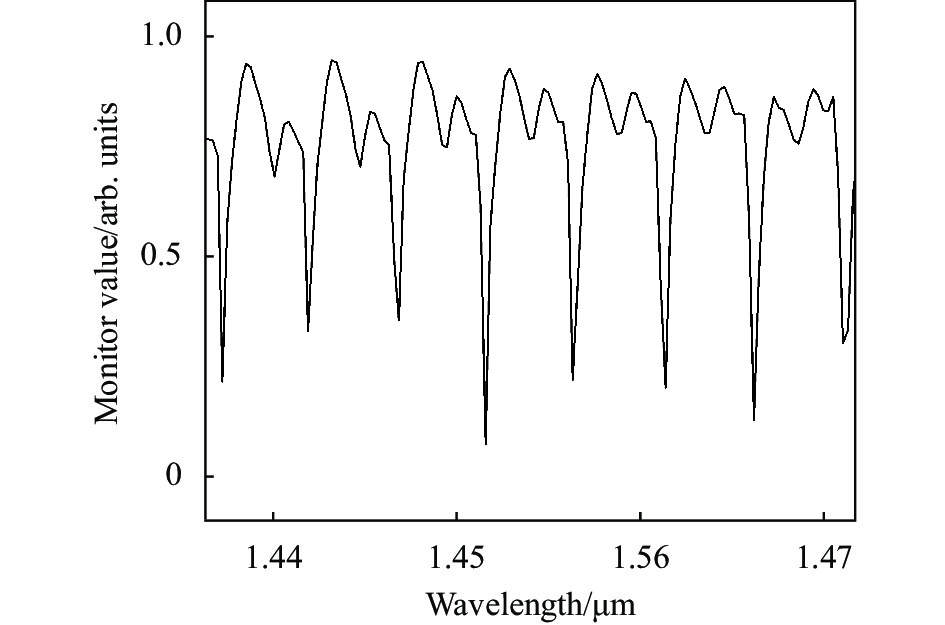
图3(a)为所设计的耦合谐振模型,背景(空气)折射率为1.0;光纤纤芯直径8.3 μm,折射率1.4505;设置微管腔内径8 μm,外径9 μm,折射率1.4446,根据理论部分公式(3)、(4)进行数值求解可以获得耦合临界角约为83°。考虑到实际器件加工制备83°抛磨角存在较大的难度,在尽可能接近耦合临界角的情况下结合实际制备工艺条件,选择75°抛磨角进行分析。设置Monitor1与Monitor2进行能量传输检测,图4所示为Monitor收集到的波谱情况,与理论分析特征相符合。

图 4 仿真WGM耦合谐振谱。(a) Monitor1;(b) Monitor2
Figure 4. Simulation of WGM coupled resonant spectrum.(a) Monitor1; (b) Monitor2
在实际应用中所使用的微管一般尺寸较大,当微管壁厚较厚时,会激发WGM的不同径向模式。在多模式情况下回音壁谐振透射谱与单一模式会有所不同,但仍属于洛伦兹凹谷谱型。重新设置微管尺寸参数,内径42 μm,外径48 μm。图5所示为模拟所获得的WGM透射谱,波谱特征与分析相符合。
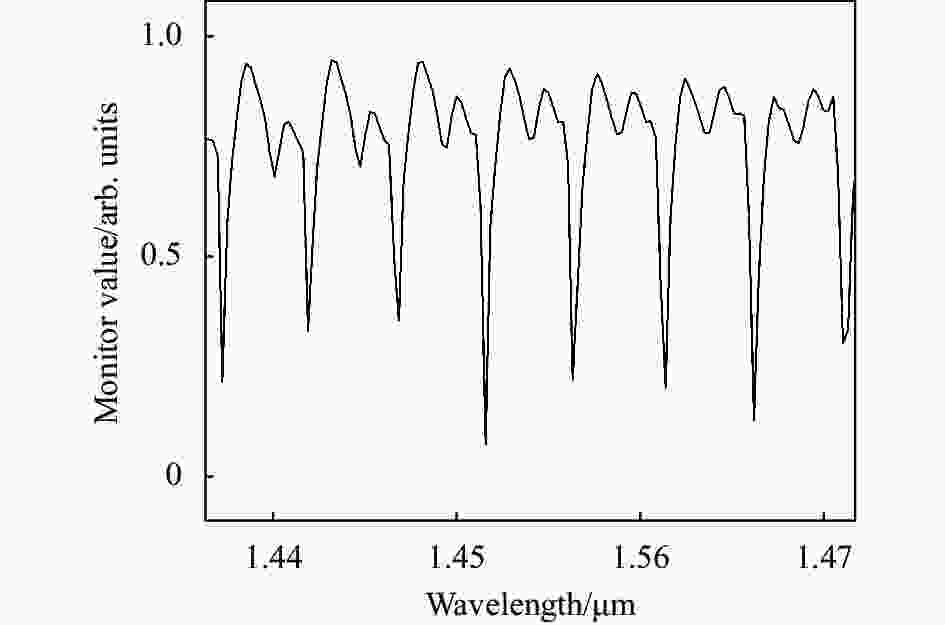
图 5 仿真WGM耦合谐振透射谱
Figure 5. Simulation of WGM coupled resonant transmission spectrum
-
楔形端面光纤的制备主要通过研磨(FibKey BFP-1-MCU)完成,系统的研磨角度可以自由调节,调节范围为20°~180°,角度控制精度为0.1°。研磨夹具配有可调电压的电源适配器,与摆臂电源适配器共用,方便研磨速度和摆臂速度的调整。根据研磨角度、研磨速度和研磨时间,可以制备不同角度的楔形端面光纤。制备75°抛磨角楔形端面光纤结构的程序参数列于表1。
表 1 制作光纤楔形端面耦合器结构的程序参数表
Table 1. Program parameters for fabrication of fiber wedge end coupler structure
Parameters Value Fiber diameter/μm 125 Strip length/mm 12 Grinding method Slope grinding Angle choice Adjustable Grinding disc speed/r·s-1 30 Ceramic ferrule Grinding time/min 30 Z axis descending speed/μm·s-1 2 Fiber Grinding time/min 1 研磨过程包括三个步骤:调节角度、研磨插芯和研磨光纤。调节角度是进行角度调整和零点定位。研磨角度设定完成后,在研磨光纤前需要根据需要预制陶瓷插芯。插芯研磨完成后,进行光纤研磨,图6所示为显微镜下研磨制备的楔形光纤图。

图 6 显微镜下楔形光纤图
Figure 6. Diagram of wedge fiber under microscope
-
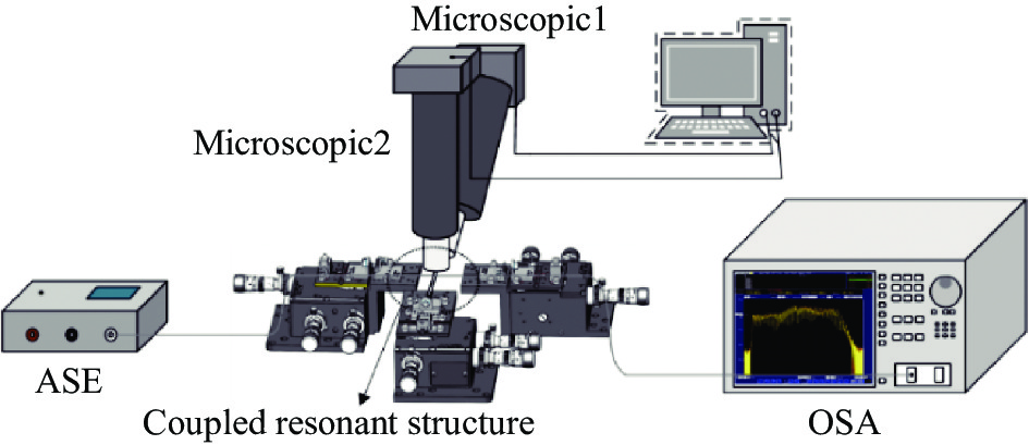
图7所示为提出的光纤楔形端面与微管腔耦合谐振激发WGM的实验测试装置。两根楔形端面光纤分别连接到宽带光源(ASE,1520~1615 nm)和光谱分析仪(OSA,AQ6370 C,YOKOGAWA)。楔形端面光纤的抛角端和微管腔通过夹具固定于高精密三维位移台上。通过三维位移台精密调节光纤楔形端面与微管腔的位置,将光耦入微管腔激发回音壁模式,耦合谐振状态下光纤楔形端面与微管腔的结构位置图如图8(a)所示。位置调节在显微镜环境下操作,由CMOS相机获取监测图像,图8(b)、(c)分别为显微镜1拍摄耦合结构正视图图像和显微镜2拍摄耦合结构俯视图图像。

图 7 耦合谐振实验测试系统
Figure 7. Coupling resonance experimental test system
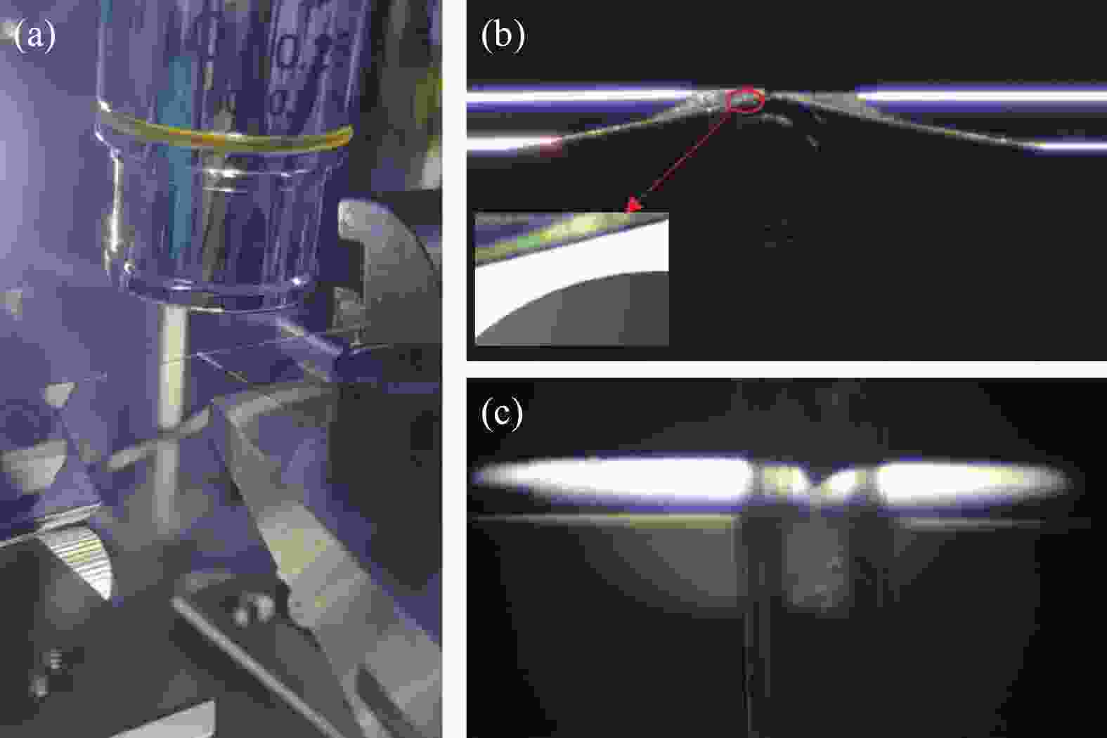
图 8 (a)光纤楔形端面与微管腔的结构位置图;(b)显微镜1拍摄耦合结构正视图图像;(c)显微镜2拍摄耦合结构俯视图图像
Figure 8. (a) The structure position diagram of the fiber wedged end face and the micropipe cavity; (b) Microscope1 captures the main view image of the coupled structure; (c) Microscope2 captures the top view image of the coupled structure
图9所示为在三维位移台精密调节耦合谐振过程中对应的不同耦合状态。在此次耦合调节中,光纤楔形端面耦合器使用单模光纤抛磨制备,抛磨角度为 75°,微管腔为外径370 μm,壁厚60 μm的石英毛细管。在微毛细管距离光纤楔形端面较远时,微管尚未进入光纤楔形端面的倏逝场中,此时耦合系统的耦合效率为0,处于欠耦合状态,如图9(a)所示。将微管与光纤楔形端面的耦合间距减小,当微管进入光纤楔形端面倏逝场时,此时部分光可以被成功耦合进入微毛细管中形成回音壁谐振,因此光谱仪所收集到的透射谱有光源光谱变成微管的WGM光谱,如图9(b)所示。再进一步减小微毛细管与光纤楔形端面的耦合间距(直至微管与光纤楔形端面接触),倏逝场充分接触,得到很好的WGM谐振,WGM光谱情况如图9(c)所示,获得较好的洛伦兹凹谷,与仿真模拟和理论分析下的波谱特征相符合。
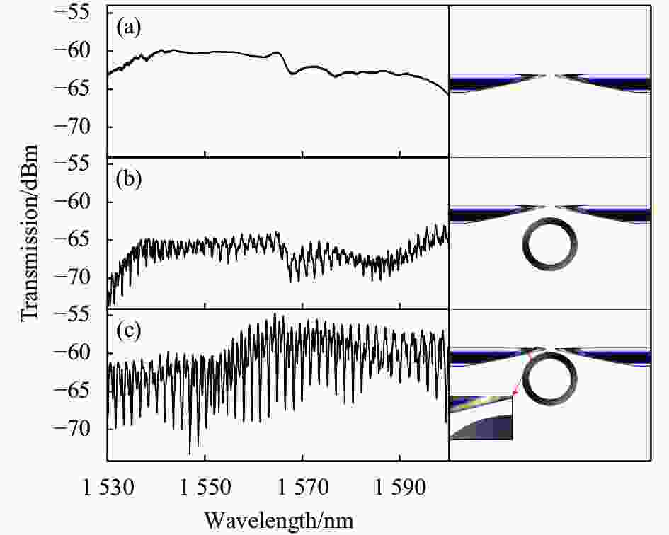
图 9 不同耦合间距的谐振光谱
Figure 9. Resonance spectra of different coupling distances
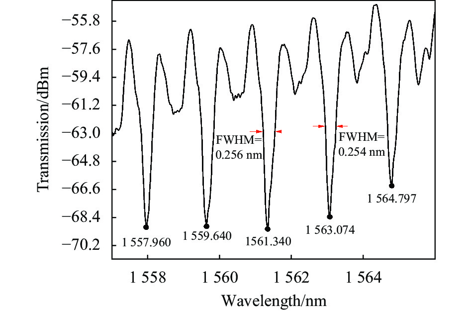
图10显示了光纤楔形端面与微管谐振器接触情况下回音壁模式谐振的局部波长透射光谱图,从图中可以看出,光谱存在显著的谐振周期,观察其中的一个周期,对应的谐振波长分别为1 561.340 nm和1 563.074 nm,由此可计算其自由光谱范围约为1.734 nm,谐振波长为1 561.340 nm对应的谐振波谷半峰全宽(Full Width at Half Maximum, FWHM)约为0.256 nm,可计算出其Q值约为6.10×10³。谐振波长为1 563.074 nm对应的谐振波谷半峰全宽约为0.254 nm,Q值约为6.15×10³。与棱镜[8]和光纤锥[10-11]耦合相比,耦合系统性能比较如表2所示,所提出的光纤楔形端面与微管耦合在具备较高鲁棒性并大大简化系统的同时,Q值相差不大。

图 10 WGM谐振透射光谱局部放大图
Figure 10. The local amplification diagram of WGM resonant transmission spectrum
表 2 针对毛细管不同耦合方式的谐振性能对比
Table 2. Comparison of different coupling methods for capillary resonance
值得注意的是,毛细管作为微反应器,内壁需要进行一定的生化反应,毛细管尺寸不宜太小。所以在分析时,使用了尺寸参数较大的毛细管,并且未经过特殊微纳加工。微管回音壁谐振的Q值与微管尺寸息息相关,之后在实际应用于传感检测应用时,可根据器件尺寸匹配进行结构参数优化,从而提高Q值和传感特性。并且还可以使用吹泡工艺对毛细管微腔进行微纳加工获得可以对WGM进行三维限制的微泡结构,从而进一步提高Q值。
-
文中提出并验证了一种用于毛细管微反应器回音壁谐振的光纤楔形端面耦合器。通过理论分析、仿真模拟和实验验证研究了光纤楔形端面与毛细管微腔的耦合谐振。楔形光纤端面以一定的倾斜角度抛磨平整,以便全内反射后的倏逝场具有与要激发WGM的微管谐振器模式相同的传播常数。当微管腔位于倏逝场的核心区域范围内时,形成楔形光纤端面与微管腔模场重叠。光纤的波导模式和毛细管回音壁模式之间发生共振,进行有效的能量交换,进而有效激发微管腔WGM谐振。文中使用抛磨角度为75°的光纤楔形端面耦合器和外径370 μm,壁厚60 μm的石英毛细管进行实验测试,通过调节不同的耦合间距,成功耦合激发WGM谐振。谐振波长1563.074 nm附近自由光谱范围约为1.734 nm,Q值约为6.15×10³。所提出的光纤楔形端面耦合器具有较好的鲁棒性,耦合谐振结构稳定,系统简单,可以有效地用于毛细管微反应器回音壁谐振的激发,对毛细管微反应器生化分析检测应用具有重要指导意义。
Fiber wedge end-face coupler for capillary whispering-gallery-mode resonators
-
摘要: 面向毛细管微反应器固相状态检测需求,提出了一种激发微管腔回音壁谐振的光纤楔形端面耦合器。建立了光纤楔形端面耦合模型,通过理论研究楔形端面与微管腔倏逝场耦合原理,仿真模拟楔形端面光场分布情况,并分析了光纤楔形端面与微管腔耦合谐振的光谱特征。研磨制备耦合器件,搭建实验系统进行实验验证。实验采集到洛伦兹凹谷型耦合谐振谱,与理论仿真分析相一致。谐振谱1563.074 nm波长附近的自由光谱范围约为1.734 nm,Q值约为6.15×10³。所提出的光纤楔形端面耦合器具有较好的器件鲁棒性,耦合谐振结构简单,易于器件集成和小型化。Abstract:
Objective For the detection requirements of the immobilization status of the inner surface modifiers in capillary microreactors, the sensing detection by exciting the optical whispering gallery mode (WGM) of the capillary microreactor can achieve highly sensitive, unmarked, and directly quantitative real-time detection of the immobilization status of the inner surface modifiers in capillary microreactors. Therefore, the study of mode excitation in capillary microreactor WGM is crucial. The near-field coupling devices commonly used for coupled resonant excitation of capillary microcavity WGM resonance are mainly prisms and fiber cones. However, the prism coupling system is complex and the devices are large and difficult to integrate and miniaturize. Fiber cone devices are fragile and have poor robustness. To meet the practical application requirements of capillary microreactor inner wall condition detection, a coupled resonant system with certain robustness and a simple system that can be integrated and miniaturized is required. To this end, an optical fiber wedge end coupler that excites the WGM resonance of a microtubular cavity is proposed. Methods A resonant model of fiber wedge end-face coupled with capillary microcavity was established (Fig.1), by theoretically studying the principle of coupling the wedge end-face to the microcavity swiftly, simulating the optical field distribution and coupling resonance of the wedge end-face (Fig.2), and analyzing the spectral characteristics of the coupling resonance of the fiber wedge end-face to the microcavity (Fig.3). The wedge-shaped end fiber (Fig.7) with 75° polishing angle was prepared by grinding (Fig.6), and the experimental system (Tab.1) was built for the corresponding experimental verification. The proposed WGM coupled resonance of wedge-shaped end surfaces and capillary microcavities is investigated by theoretical analysis, simulation, and experimental verification. Results and Discussions Simulation of the coupling of the fiber wedge end-face to the microtubular cavity is conducted using RSoft software. The fiber wedge end-face can be successfully coupled (Fig.2) to excite WGM resonance by choosing a suitable angle for phase matching and mode field overlap with the capillary microcavity. The transmission spectrum obtained from the coupled structure shows a Lorentz concave valley (Fig.4), which is consistent with the theoretical analysis. In the experiments, different coupling resonance states can be obtained by adjusting the coupling spacing (Fig.9) using two wedge-terminated fibers with polishing angle of 75°. The Lorentz concave-valley type coupled resonance spectrum (Fig.10) is collected, which is consistent with the theoretical study and simulation analysis. The free spectral range near the wavelength of the resonance spectrum 1 563.074 nm is about 1.734 nm and the Q value is about 6.15 × 10³. The proposed fiber wedge end coupler can effectively excite the WGM mode of the capillary microcavity. Conclusions A fiber wedge end coupler for excitation of microtubular cavity WGM resonance is proposed. The coupler has good robustness, the coupling resonance structure is stable, and the system is simple and easy to be integrated into a small size. A suitable polishing angle is selected for the end-face of the wedge fiber to meet the phase-matching condition of WGM. By adjusting the appropriate coupling spacing, the wedge-shaped fiber end surfaces are formed to overlap with the microtubular cavity mode field. Resonance between the fiber optic waveguide mode at the wedge end-face and the capillary WGM mode occurs for effective energy exchange, which in turn effectively excites the capillary microcavity WGM. The coupling structure was simulated and analyzed using RSoft, and the system was built. Experimental tests were performed using an optical fiber wedge end coupler with a polishing angle of 75° and a quartz capillary with an outer diameter of 370 μm and a wall thickness of 60 μm. The experiment was successfully coupled to excite the WGM resonance with a free spectral range of about 1.734 nm near the resonance wavelength of 1 563.074 nm and a Q value of about 6.15 × 10³. The proposed fiber optic wedge end coupler can be effectively used for mode excitation of capillary microreactor WGM resonance, which is an important guideline for capillary microreactor biochemical assay applications. -
Key words:
- whispering gallery mode /
- capillary /
- fiber optical coupler /
- wedge end-face
-
图 1 光纤楔形端面与微管腔的耦合谐振
Figure 1. The coupling resonance of fiber wedge end face and micro-tubular cavity
图 2 不同抛角θ楔形端面光纤的光场分布与耦合谐振状态
Figure 2. Optical field distribution and coupled resonance states of wedge-terminated fibers with different throw angles θ
图 3 (a)光纤楔形端面与微毛细管耦合结构的仿真设计;(b)洛伦兹型尖峰特征光谱;(c)洛伦兹型凹谷特征光谱。
Figure 3. (a) Simulation design of coupling structure of fiber wedged end face and micro capillary tube; (b) Characteristic spectrum of Lorentz peak; (c) Characteristic spectrum of Lorentz dip
图 4 仿真WGM耦合谐振谱。(a) Monitor1;(b) Monitor2
Figure 4. Simulation of WGM coupled resonant spectrum.(a) Monitor1; (b) Monitor2
图 8 (a)光纤楔形端面与微管腔的结构位置图;(b)显微镜1拍摄耦合结构正视图图像;(c)显微镜2拍摄耦合结构俯视图图像
Figure 8. (a) The structure position diagram of the fiber wedged end face and the micropipe cavity; (b) Microscope1 captures the main view image of the coupled structure; (c) Microscope2 captures the top view image of the coupled structure
图 10 WGM谐振透射光谱局部放大图
Figure 10. The local amplification diagram of WGM resonant transmission spectrum
表 1 制作光纤楔形端面耦合器结构的程序参数表
Table 1. Program parameters for fabrication of fiber wedge end coupler structure
Parameters Value Fiber diameter/μm 125 Strip length/mm 12 Grinding method Slope grinding Angle choice Adjustable Grinding disc speed/r·s-1 30 Ceramic ferrule Grinding time/min 30 Z axis descending speed/μm·s-1 2 Fiber Grinding time/min 1  下载: 导出CSV
表 2 针对毛细管不同耦合方式的谐振性能对比
Table 2. Comparison of different coupling methods for capillary resonance
下载: 导出CSV
-
[1] 柏淼鑫, 金俪阳, 朱涛, 等. 基于聚合物微球腔的高灵敏温度传感器(特邀)[J]. 红外与激光工程, 2022, 51(10): 20220535. doi: 10.3788/IRLA20220535 Bai Miaoxin, Jin Liyang, Zhu Tao, et al. High sensitivity temperature sensor based on polymer microsphere cavity (invited) [J]. Infrared and laser engineering, 2022, 51(10): 20220535. (in Chinese) doi: 10.3788/IRLA20220535 [2] Jiang Xuefeng, Abraham J Q, Lan Yang, et al. Whispering-gallery sensors [J]. Matter, 2020, 3(2): 371-392. doi: 10.1016/j.matt.2020.07.008 [3] Cai Lu, Pan Junyao, Xiao Shiyuan, et al. Whispering gallery mode optical microresonators: structures and sensing applications [J]. Physica Status Solidi A, 2020, 217(6): 1862-6300. [4] White I M, Oveys H, Fan X. Liquid core optical ring resonator sensors [J]. Optics Letters, 2006, 31(9): 1319-1321. doi: 10.1364/OL.31.001319 [5] Wang Y, Zhang H, Xiang D, et al. Real-time conformational change monitoring of g-quadruplex using capillary-based biocompatible whispering gallery mode microresonator [J]. IEEE Sensors Journal, 2020, 20(21): 12558-12564. doi: 10.1109/JSEN.2020.3002913 [6] Wang Ziyihui, Liu Yize, Liu Tiegen, et al. Ultra-sensitive DNA zyme-based optofluidic biosensor with liquid crystal-Au nanoparticle hybrid amplification for molecular detection [J]. Sensors and Actuators B: Chemical, 2022, 359: 0925-4005. [7] Cai Lu, Pan Junyao, Hu Sheng. Overview of the coupling methods used in whispering gallery mode resonator systems for sensing [J]. Optics and Lasers in Engineering, 2020, 127: 105968. [8] 江俊峰, 张晶, 陈文杰, 等. 微管回音壁谐振模径向模式的影响[J]. 光学学报, 2013, 33(12): 306-310. Jiang Junfeng, Zhang Jing, Chen Wenjie, et al. Effect of radial mode of whispering gallery resonance mode in microtubules [J]. Acta Optica Sinica, 2013, 33(12): 306-310. (in Chinese) [9] 杨旭, 李亚明, 刘旭东, 等. 拉曼增益对回音壁模式光学微腔的全光调制[J]. 红外与激光工程, 2017, 46(11): 264-268. doi: 10.3788/IRLA201746.1122003 Yang Xu, Li Yaming, Liu Xudong, et al. All-optical modulation of Raman gain on whispering gallery mode optical microcavity [J]. Infrared and Laser Engineering, 2017, 46(11): 1122003. (in Chinese) doi: 10.3788/IRLA201746.1122003 [10] Niu Panpan, Jiang Junfeng, Liu Tiegen, et al. High-sensitive and disposable myocardial infarction biomarker immunosensor with optofluidic microtubule lasing [J]. Nanophotonics, 2022, 11(14): 3351-3364. doi: 10.1515/nanoph-2022-0208 [11] Liu Yu, Yang Huihui, Guo Junqi, et al. A whispering gallery mode strain sensor based on microtube resonator [J]. Optoelectronics Letters, 2021, 17(4): 199-204. doi: 10.1007/s11801-021-0069-7 [12] Shu FangJie, Zou Changling, Sun Fangwen. Perpendicular coupler for whispering-gallery resonators [J]. Optics Letters, 2012, 37(15): 3123-3125. [13] Ilchenko V S, Yao X S, Maleki L. Pigtailing the high-Q microsphere cavity: a simple fiber coupler for optical whispering-gallery modes [J]. Optics Letters, 1999, 24(11): 723-725. doi: 10.1364/OL.24.000723 [14] Hanumegowda NM, Stica CJ, Patel BC, et al. Refractometric sensors based on microsphere resonators [J]. Appl Phys Lett, 2005, 87(20): 201107. doi: 10.1063/1.2132076 [15] Hanumegowda NM, White IM, Oveys H, et al. Label-free protease sensors based on optical microsphere resonators [J]. Sensor Letters, 2005, 3(3): 315-319. [16] Liu X, Zhang X, Zhang Q, et al. Trapezoidal angled fiber coupler for microsphere resonator with enhancement of fano resonance [J]. IEEE Photonics Technology Letters, 2022, 34(20): 1073-1076. doi: 10.1109/LPT.2022.3200379 [17] Zhu Hongying, White I M, Fan Xudong, et al. Analysis of biomolecule detection with optofluidic ring resonator sensors [J]. Optics Express, 2007, 15(15): 9139-9146. doi: 10.1364/OE.15.009139 -

 点击查看大图

计量
- 文章访问数: 98
- HTML全文浏览量: 28
- PDF下载量: 29
- 被引次数: 0

