


-
随着航天技术的不断发展,人类在外太空的活动越来越多,所产生的空间碎片也日益增多,为了规避或者清除空间碎片[1],需要有效和快速地对碎片进行监测,大视场空间相机因为具有较高的探测效率而逐渐成为观测空间碎片的重要方式。在实际成像过程中,由于卫星自身在轨姿态的运动和二维转台的转动等因素,导致图像上产生像旋,影响空间目标识别的准确率和定位精度,特别是在对空间中的暗弱目标进行观测时,为了图像更清晰,需要延长相机的曝光时间,曝光时间越长,图像上的像旋越严重。因此,对大视场空间相机进行像旋补偿具有极其重要的意义。
目前,国内外主要的像旋补偿手段根据消旋方式主要可以分为三种,分别是电子消旋、光学消旋和物理消旋。电子消旋也被称作数字消旋[2-4],是将图像上的每个像素点按所产生的像旋角进行反向旋转,对像素点重新排列来实现对相机像旋的补偿,但是电子消旋的图像数据量较大,运算时间较长,无法做到实时消像旋,另一方面数字消像旋会造成视场变小,对成像光学系统提出更高的要求。光学消旋[5]是在光学成像系统前沿光轴方向安装消旋棱镜(如K镜、45°镜)进行消旋,光学消旋在航空相机上的使用比较多,如邱兆文等提出的一种四反射镜结构稳像平台[6];王昱棠等对航空相机光学消旋的控制系统进行了详细的研究[7],大视场空间相机需要对暗弱目标进行观测,光学消像旋会在成像过程中产生光能量的损失,且加装光学消旋器件会使载荷的重量增加,从而导致发射成本增加。物理消旋也称作机械消旋[8],主要消旋原理是在成像器件上加装精密机械结构及控制系统,在成像时直接驱动成像器件旋转,使像面按像旋角同步转动,从而对像旋进行补偿,虽然物理消旋对系统的成像影响较小,但也会使系统载荷的重量增加,且齿轮传动存在较大的传动间隙,消旋精度难以保证。
柔性铰链是一种具有体积小、结构紧凑、精度高等特点的新型回转运动副。因其没有摩擦和无需润滑而被广泛应用在航空航天、精密定位、机器人和精密光学等各种领域[9-14]。李林提出了一种基于柔性铰链的新型消旋机构[15],解决了传统机械消旋体积过大存在传动间隙的缺点,提升了消旋精度,但是由于采用了上下层的结构,在补偿过程中会出现新的寄生运动,产生新的像移困扰。
针对以上问题,文中提出了一种新型的基于对称右直圆柔性铰链的内外圈形式的像旋补偿机构,并通过给定信息确定像旋补偿的性能指标。之后通过卡氏第二定理计算了柔性铰链的柔度,对像旋补偿机构的性能进行了理论验证,然后通过约束条件对机构进行优化设计,并通过有限元仿真对其结果进行验证。结果表明,该机构可以完成对大视场空间相机的像旋补偿,并具有较高的精度。
-
大视场空间相机在轨成像期间,采用二维转台实现特定天区成像。但是,由于平台的轨道运动,在单帧成像积分时间内,探测目标在像面上产生像旋,目标依次成像在多个像元上,降低成像信噪比,导致目标探测概率、质心定位精度等降低。为了简化分析流程,清晰表示空间三维图像位置变换关系,王家骐、颜昌翔[16-18]等提出使用齐次坐标变换方法来描述动态光学成像特性。
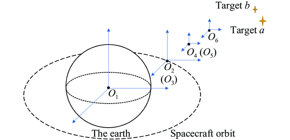
当大视场相机对目标a、b进行观测时,可以建立如图1所示的系统成像坐标系,各坐标系均为右手笛卡尔坐标系,坐标系O1-xyz为地心坐标系;坐标系O2-xyz为航天器轨道坐标系;坐标系O3-xyz为航天器质心坐标系,当航天器不存在姿态运动时,航天器本体坐标系与航天器轨道坐标系重合;坐标系O4-xyz为遥感相机坐标系;坐标系O5-xyz为相机物方坐标系,当定位目标a处于物方坐标系z轴时,相机物方坐标系与遥感相机坐标系重合;坐标系O6-xyz坐标系原点位于像面中心的像方坐标系。
通过齐次坐标变换法将所有坐标最终都转换到地心坐标系,然后将给定卫星的初始姿态和轨道参数及两个恒星坐标代入,设定相机成像积分时间为3 s,成像期间的像旋角速度最大为30 (″)/s,可以计算得到大视场空间相机存在±1.5′的像旋角度。对成像系统像旋效果仿真分析,得到的结果如图2所示。
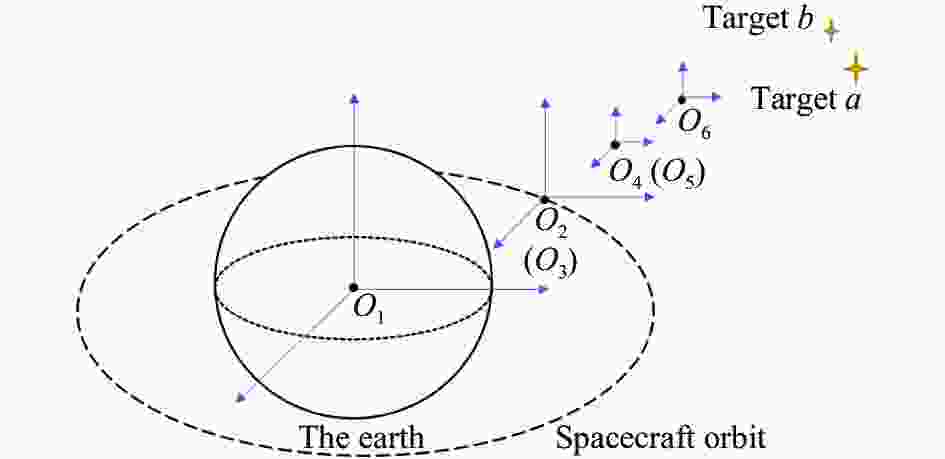
图 1 系统成像坐标系
Figure 1. System imaging coordinate system

图 2 像旋效果仿真分析
Figure 2. Simulation analysis of image rotation effect
从图2可以看出,成像时,在像面上产生了严重的拖影,且拖影距离远大于探测器单个像元尺寸,所以必须对相机进行像旋补偿。考虑到结构装调过程中存在一定的误差,故像旋补偿机构按照补偿角度范围±2′开展设计,根据光学成像要求,成像镜筒最大直径为266 mm,像旋补偿角度范围内的最大位移量约为77 μm。
-
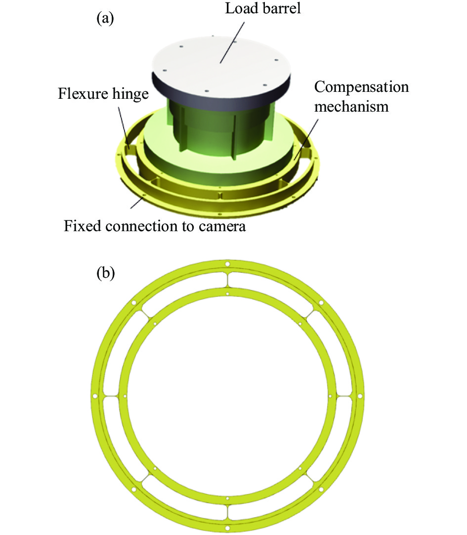
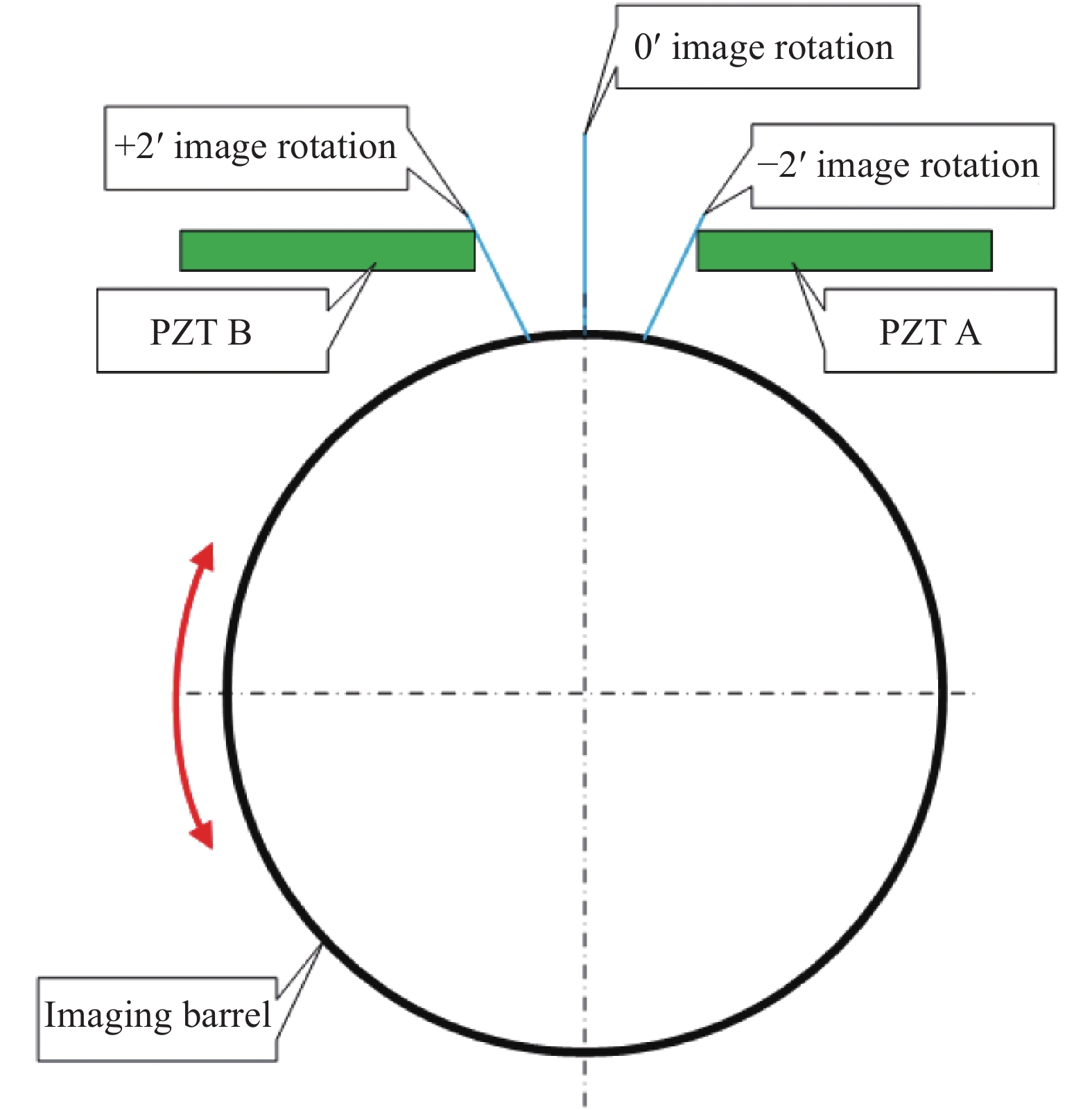
针对该大视场空间相机,设计了一种基于压电驱动器和柔性单元的双圆环结构的像旋补偿机构,像旋补偿系统由相机、像旋补偿机构、压电陶瓷驱动器(PZT)和距离传感器组成,如图3(a)所示,像旋补偿机构内圈作为活动件与镜筒相连接,外圈作为固定件与相机底座相连。当相机在成像过程中发生像旋时,系统计算存在的像旋角度,然后像补偿系统发送消旋指令,PZT器件驱动镜筒带动相机的光学系统顺时针和逆时针转动实现对像旋的正反向补偿。如图4所示,PZT器件A实现逆时针方向像旋补偿,PZT器件B实现顺时针方向像旋补偿。像旋补偿机构由八个完全一样的均匀分布的柔性单元组成(图3(b)),因此八个柔性单元之间的轴向力可以互相抵消,从而减少了非工作方向的寄生运动的产生,保证像旋补偿时中心轴的位置保持在旋转中心,避免了再次出现像移。

图 3 像旋补偿机构示意图
Figure 3. Schematic diagram of image rotation compensation mechanism

图 4 像旋补偿原理
Figure 4. Image rotation compensation principle
综合考虑机构运动、PZT驱动力、运动控制等因素,结构设计为:0′像旋补偿位置对应柔性单元自由位置。因此,−2′像旋补偿位置、+2′像旋补偿位置时,柔节因变形产生的旋转阻力最大。为实现±2′像旋补偿角度范围,逆时针像旋补偿时,在+2′像旋补偿位置,PZT器件A的驱动力应大于柔节的阻力;顺时针像旋补偿时,在−2′像旋补偿位置,PZT器件B的驱动力应大于柔节的阻力。
-
在该像旋补偿机构中,柔节相当于一个弹簧,受力时柔性单元发生弹性形变,内环带动镜筒正反向旋转,外环固定不动,外力取消后,像旋补偿机构恢复原态。八个柔性单元完全一样,放大单个柔性单元机构如图5所示,主要由三部分组成,左右是完全对称的半径为$ r $的四分之一圆,中间部分由恒定宽度为$ t $、长度为$ l $的直梁组成。
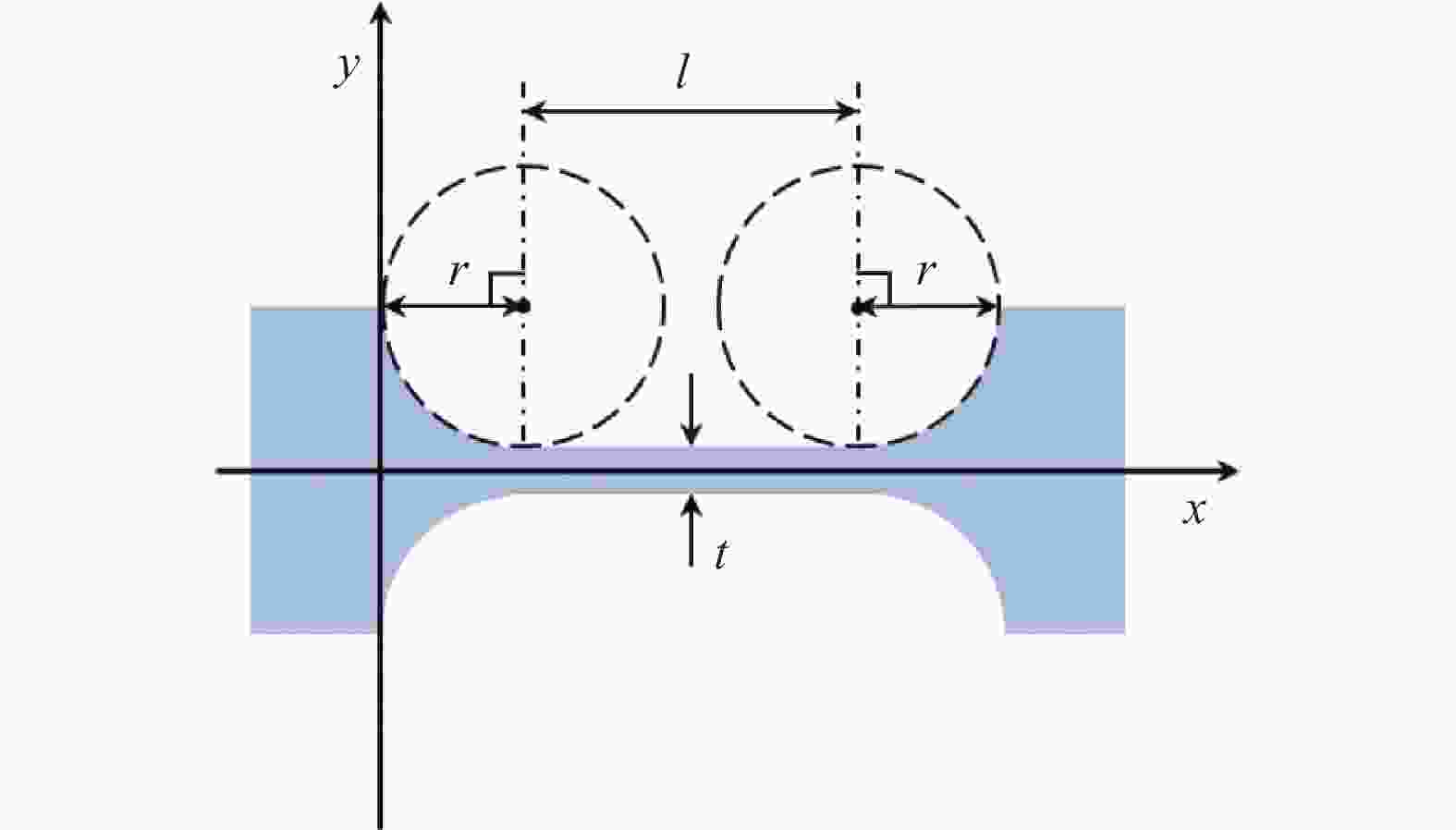
图 5 单个柔性单元机构
Figure 5. Single flexible unit mechanism
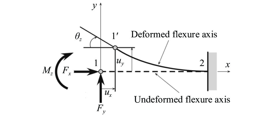
因此,在计算像旋补偿机构时,通过对单个柔性单元的受力分析进行计算,就可以计算出整体像旋补偿的受力变形。如图6所示,在对单个柔性单元进行受力分析时,假设一端固定,另一端为自由端,在主要转动平面内作用在柔性单元自由端的主要有$ {{F}}_{{x}} $、$ {{F}}_{{y}} $和$ {{M}}_{{z}} $三个载荷,在此三个载荷的作用下产生三个方向的位移$ {\;{\mu }}_{{x}} $、$ {\;{\mu }}_{{y}} $和$ {{\theta }}_{{z}} $。设$ {F}={\left[ {{F}}_{{x}},{{F}}_{{y}},{{M}}_{{z}}\right]}^{{\rm{T}}} $,$ {U}={\left[ \;{{\mu }}_{{x}},\;{{\mu }}_{{y}},{{\theta }}_{{z}}\right]}^{{\rm{T}}} $,根据力学知识和卡氏第二定理[11,19]可得:

图 6 像旋补偿原理
Figure 6. Image rotation compensation principle
$$ U=CF $$ (1) 式中:C为柔性单元的柔度矩阵。用$ {{C}}_{{a},{b}} $表示载荷b引起的在a方向的柔度,其被定义为:
$$ C=\left[\begin{array}{ccc}{C}_{x,{F}_{x}}& 0& 0\\ 0& {C}_{y,{F}_{y}}& {C}_{y,{M}_{z}}\\ 0& {C}_{z,{F}_{y}}& {C}_{z,{M}_{z}}\end{array}\right] $$ (2) 其中,各柔度表达式为:
$$ \left\{\begin{array}{c} C_{x, F_{x}}=\dfrac{1}{E w} \displaystyle\int_{0}^{L} \dfrac{{\rm{d}} x}{t(x)} \\ C_{y, F_{y}}=\dfrac{12}{E w} \displaystyle\int_{0}^{L} \dfrac{x^{2} {\rm{d}} x}{t(x)^{3}} \\ C_{y, M_{z}}=\dfrac{12}{E w} \displaystyle\int_{0}^{L} \dfrac{x {\rm{d}} x}{t(x)^{3}} \\ C_{z, F_{y}}=\dfrac{12}{E w} \displaystyle\int_{0}^{L} \dfrac{x {\rm{d}} x}{t(x)^{3}} \\ C_{z, M_{z}}=\dfrac{12}{E w} \displaystyle\int_{0}^{L} \dfrac{{\rm{d}} x}{t(x)^{3}} \end{array}\right. $$ (3) 式中:E为柔性单元所用材料的弹性模量;w为柔性单元的纵向宽度;t(x)为柔性单元切口厚度函数。在文中所选的柔性单元中,t(x)表达式为:
$$ {t}\left(x\right)=\left\{\begin{array}{c}t+2\left[r-\sqrt{x\left(2r-x\right)}\right]\\ t\\ t+2\left[r-\sqrt{{r}^{2}-(x-l-r{)}^{2}}\right]\end{array}\right.\begin{array}{cc}& x\in \left[0,r\right)\\ & x\in \left[r,l+r\right]\\ & x\in \left(l+r,l+2r\right]\end{array} $$ (4) -
理想情况下,柔性单元工作运动时转动中心固定不动,但实际工作过程中,柔性铰链在受到载荷影响下会产生微小的弹性变形,因此,使用柔性铰链回转中心的偏移量作为转动精度的评价。与柔性铰链柔度定义相似,将柔性铰链回转中心位移量设为$ {{\nu }}_{{x}} $和 $ {{\nu }}_{{y}} $,设$ {V}={\left[ {{\nu }}_{{x}},{{\nu }}_{{y}}\right]}^{{\rm{T}}} $,可以得到:
$$ {V}=C^{0} {F} $$ (5) 式中:$ {C}^{0} $为柔性单元的精度矩阵。用$ {C}_{a,{b}}^{0} $表示载荷b引起的在a方向柔性铰链的精度,当忽略平面外载荷时其被定义为:
$$ \left[C^{0}\right]=\left[\begin{array}{ccc} C_{x,{F_{x}}}^{0} & 0 & 0 \\ 0 & C_{y, F_{y}}^{0} & C_{y{,} M_{z}}^{0} \end{array}\right] $$ (6) 其中,各精度的具体表达式为:
$$ \left\{\begin{array}{l} C_{x, F_{x}}^{0}=\dfrac{1}{E w} \displaystyle\int_{0}^{L} \dfrac{{\rm{d}} x}{t(x)} \\ C_{y, F_{y}}^{0}=\dfrac{12}{E w} \displaystyle\int_{0}^{L} \dfrac{x^{2} {\rm{d}} x}{t(x)^{3}} \\ C_{y, M_{z}}^{0}=\dfrac{12}{E w}\left(\displaystyle\int_{0}^{L} \dfrac{x {\rm{d}} x}{t(x)^{3}}-L \displaystyle\int_{0}^{L} \dfrac{{\rm{d}} x}{t(x)^{3}}\right) \end{array}\right. $$ (7) -
将公式(4)代入公式(3)中可以得到柔性单元在各个方向上的柔度函数,则在主要的工作方向上柔度为:
$$ \begin{split} {C}_{z,{M}_{z}}=& \frac{12}{Ew}\left[\frac{l}{{t}^{3}}+\frac{2r\left(6{r}^{2}+4rt+{t}^{2}\right)}{{t}^{2}\left(2r+t\right){\left(4r+t\right)}^{2}}+\right.\\ & \left. \frac{6r\left(2r+t\right)}{{\left(4r+t\right)}^{{5}/{2}}\cdot {t}^{{5}/{2}}}\arctan\sqrt{1+4\dfrac{r}{t}}\right] \end{split} $$ (8) 在主要的工作方向上精度为:
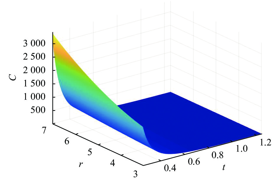
$$ {C}_{x,{F}_{x}}^{0}=\dfrac{1}{2Ew}\left[{l}/{{t}}+\dfrac{2\left(2{r}/{t}+1\right)}{\sqrt{1+4{r}/{t}}}\arctan\sqrt{1+4{r}/{t}}-{{\pi }}/{2}\right] $$ (9) 其中,假定l+2r=20 mm,w初始设计为20 mm,柔度和精度主要与圆角r和厚度t相关,柔度与r、t的关系如图7所示,精度与r、t的关系如图8所示。

图 7 工作方向柔度与r、t的关系
Figure 7. Relationship between flexibility of working direction and r, t
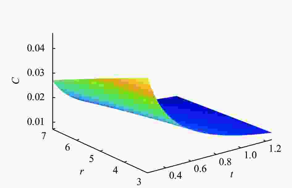
图 8 工作方向精度与r、t的关系
Figure 8. Relationship between working direction accuracy and r, t
从图7、图8可以看出柔性单元柔度和精度与设计参数的对应关系。柔性单元圆角r越大,直梁厚度t越小,该结构的柔度越大;反之,r越小,t越大,该结构的柔度越小。对于柔性单元的精度,r和t越小,柔性单元的精度越高。
-
设像旋补偿工作过程中压电驱动器所需要带动镜筒转动的角度为$ {\theta } $,相机镜筒的半径(相机补偿机构内圈半径)为R,根据力学知识和参考文献[20]可以得到该像旋补偿机构单个柔性单元所需要的驱动力$ {{F}}_{{y}} $和$ {{M}}_{{z}} $,其中:
$$ F_{y}=\frac{R C_{z, M_{z}}+C_{z, F_{y}}}{C_{z, M_{z}} \cdot C_{y, F_{{y}}}-C_{z, F_{y}}^{2}} \theta $$ (10) $$ M_z=\frac{R C_{y, M_z}+C_{y, F_y}}{C_{z, M_z} \cdot C_{y, F_y}-C_{y, M_z}^2} \theta $$ (11) 由公式(3)可知$ {C}_{z,{F}_{y}}={C}_{y,{M}_{z}} $,因为整个像旋补偿机构是完全对称的,所以得出整个机构所需要的总体力矩$ {M}={N}\times \left(R\times {F}_{y}+{M}_{z}\right) $。将公式(10)和(11)代入M可得:
$$ {M}={N} \theta \cdot \frac{R^2 C_{z, M_z}+2 R C_{y, M_z}+C_{y, F_y}}{C_{z, M_z} \cdot C_{y, F_y}-C_{y, M_z}^2} $$ (12) 同时可以计算单个柔性单元的最大应力$ {\sigma } $,如公式(13)所示:
$$ \sigma=6 k_{b} \frac{M_{z}+\left(-F_{y}\right) l}{w t^{2}}+k_{t} \frac{F_{{x}}}{w t} $$ (13) 式中:$ {k}_{b}、{k}_{t} $均为应力集中系数。
将像旋补偿机构看作质量刚度系统,设系统的转动惯量为J,相应的转动刚度为K,系统工作方向上的谐振频率为f(基频),f可以近似表示为:
$$ {f}=\frac{1}{2 \pi} \sqrt{\frac{K}{J}}=\frac{1}{2 \pi} \sqrt{\frac{M}{J \theta}} $$ (14) -
根据系统设计要求及相关技术指标,像旋补偿系统的像旋补偿角度$ {\theta }=\pm {2}{{{'}}} $,像旋补偿机构内圈半径按照R=135 mm设计。为避免发生共振,要求像旋补偿机构的基频远高于控制系统伺服带宽$ {f}_{c} $(60 Hz),一般要求系统的谐振频率$ {f} $为控制带宽$ {f}_{c} $的2~4倍。为满足空间探测的复杂环境要求,该像旋补偿机构实际应用时选用TC4材料,E=110 GPa,材料疲劳应力为660 MPa,则柔性机构中的最大应力不大于安全系数取2时的许用应力。结合空间相机实际的工作背景,取初始设计的尺寸t=0.5 mm,r=5 mm,w=20 mm,l=10 mm。
根据以上技术要求, 可以得到如下的约束条件:
$$ \begin{split} &{f} \geqslant 120\;{{\rm{Hz}}}\\ & {\sigma } \leqslant 330\;{{\rm{MPa}}} \end{split}$$ -
根据系统的设计要求,可以得到具体的优化设计模型如下:
$$\begin{split} & {f}_{{{\rm{obj}}}}=\min \left({M}_{(r,l,t,w)}\right)=\min({M}_{\left(x\right)}) \\ & \text{}\text{suppose:}{x}_{1}=r,{x}_{2}=l,{x}_{3}=t,{x}_{4}=w \\ & x={\left({x}_{1},{x}_{2},{x}_{3},{x}_{4}\right)}^{\text{T}} \end{split} $$ 约束条件:
$$ \left\{\begin{array}{l} {[2,1,0,0 ; 2,0,1,0] \leqslant x \leqslant [20 ; 13]} \\ {[4.5 ; 8 ; 0.25 ; 15] \leqslant x \leqslant[5.5 ; 10 ; 0.75 ; 25]} \\ -M+J \theta(240 \pi)^{2} \leqslant 0 \\ \sigma-3.3 \times 10^{8} \leqslant 0 \end{array}\right. $$ -
遗传算法(Genetic Algorithm, GA)是模拟达尔文生物进化论中的适者生存的生物进化过程的一种计算模型,是一种通过模拟自然进化过程搜索最优解的方法。遗传算法是模仿自然界生物进化机制发展起来的随机全局搜索和优化方法,它通过将实际模型转化为数学模型,将寻找最优解的过程对应地转化为生物进化过程中的选择、交叉和变异,通过不断的迭代寻找最优解。遗传算法的本质是一种在数学模型内搜索寻找最优解的方法,它可以在在搜索过程中自动获取和积累有关搜索空间的知识,并自适应地控制搜索过程以求得最佳解[21]。遗传算法的基本运算过程如图9所示。
将之前得到的数学模型代入Matlab优化工具箱的遗传算法中,可以得到最优化求解结果X=(5.491, 9.001, 0.518, 17.88)T,考虑到实际加工要求和系统设计要求,对所得的结果近似求解,可以得到结果X=(5.5, 9, 0.5, 18)T。因此,设计得到的柔性单元的最终设计尺寸为t=0.5 mm,r=5.5 mm,w=18 mm,l=9 mm。
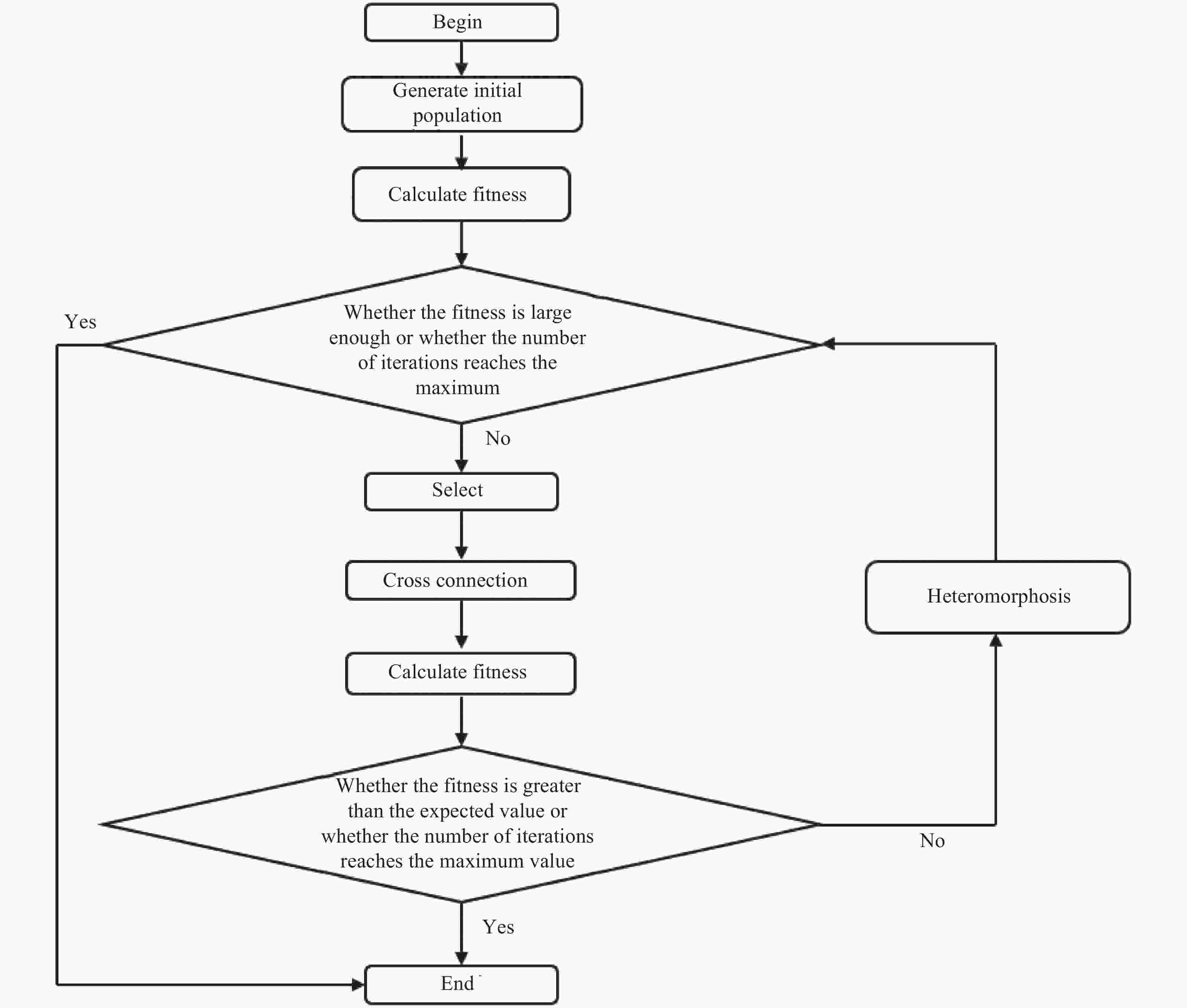
图 9 遗传算法流程图
Figure 9. Genetic algorithm flow chart
-
在完成像旋补偿机构的优化设计之后,使用UG将优化完成的像旋补偿机构进行重新三维建模,之后通过Hypermesh软件对其进行有限元前处理,具体的三维结构图和有限元网格划分分别如图10(a)和图10(b)所示。
然后对像旋补偿机构有限元静力学仿真分析,假定像旋补偿机构底部通过螺栓进行完全固定,在机构负载为450 N的状态下,两侧压电陶瓷驱动器总驱动力为115 N。对像旋补偿机构内环两测对称的各施加57.5 N的外力,对此时机构的位移和应力进行仿真分析。
仿真分析结果位移变量如图11 (a)所示,对柔性单元的放大变形量如图11 (b)所示,此时平面内最大位移分量为77.5 μm,与理论计算模型误差为1.79%,远小于5%,符合系统的设计要求。仿真结果的应力变形如图12(a)所示,最大应力出现在柔性单元的直梁位置(如图12(b)所示),此时最大应力为65 MPa,远远小于许用应力330 MPa ,符合系统的设计需求,该像旋补偿机构具有较高的稳定性和安全性。
在对像旋补偿机构完成静力学仿真之后搭建实验平台,对其进行实验验证分析,主要测试流程:将像旋补偿机构外环固定在气浮平台上,内环施加有垂直向下的45 kg的负载(如图13所示)。为了避免实验误差,需要对像旋补偿机构进行多处位置测量,在像旋补偿机构内环外侧边缘做四处测试记号,分别记录在施加0~150 N外力(以15 N为间隔选取10个点)情况下各处测试记号的位移。为了提升实验精度,实验取四处数据的平均值。
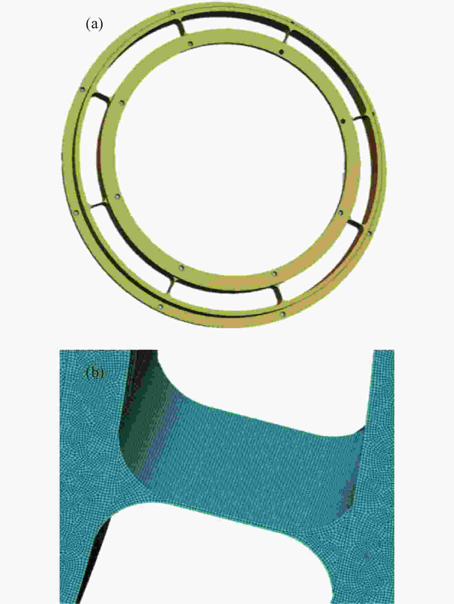
图 10 (a) 优化后的像旋补偿机构;(b)像旋补偿机构有限元模型
Figure 10. (a) Optimized image rotation compensation mechanism; (b) Finite element model of image rotation compensation mechanism

图 11 位移变形仿真
Figure 11. Displacement deformation simulation
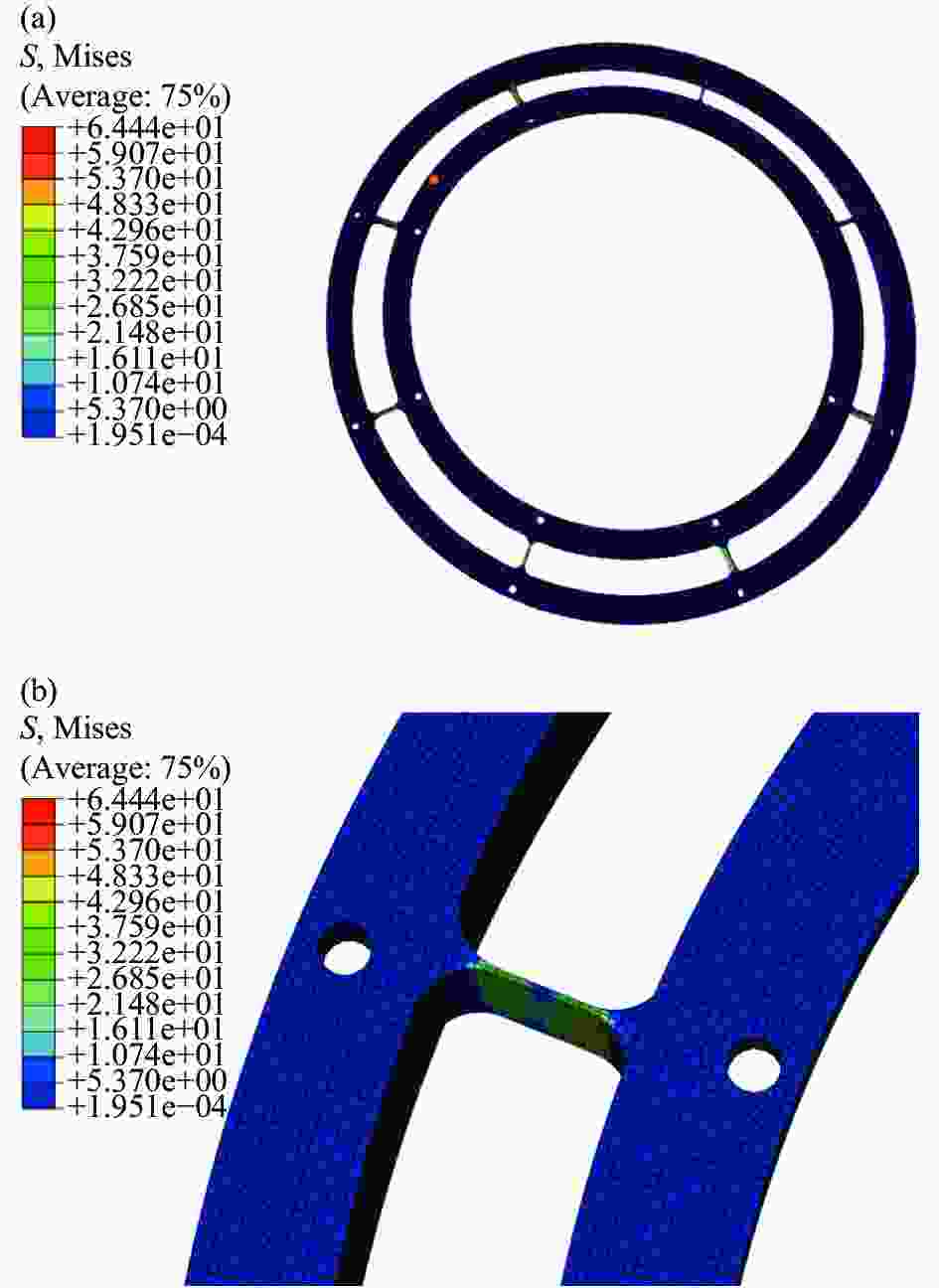
图 12 应力变形仿真
Figure 12. Stress deformation simulation

图 13 像旋补偿机构的力-位移测试实验
Figure 13. Force-displacement test experiment of image rotation compensation
主要的实验数据记录如表1所示。
表 1 力-位移实验测试数据
Table 1. Test data of force-displacement experiment
Outside force/N First place Second place Third place Fourth place Average value/μm 15 13 12 13 13 12.75 30 20 20 21 20 20.25 45 29 28 29 31 29.25 60 39 39 39 37 38.50 75 47 47 48 49 47.75 90 59 57 57 58 57.75 105 68 67 68 66 67.25 120 76 78 77 79 77.50 135 87 86 88 87 87.00 150 98 97 97 95 96.75 绘制相应的力-位移(转角)曲线(如图14所示),可以看出,在工作区间内,像旋补偿机构具有很好的线性度,即该像旋补偿机构具有良好的性能。然后计算相应的转角,并将计算结果与有限元仿真数据进行对比,计算误差。

图 14 像旋补偿机构力-位移图
Figure 14. Force-displacement diagram of image rotation compensation mechanism
根据实验数据可知,所设计的像旋补偿机构具有较好的刚度,在工作范围内得到的系统具有良好的线性度。由表2可知,实验数据与理论计算结果误差最大为2.5%,均小于5%,符合要求,验证了理论推导的可行性,验证说明了像旋补偿机构的合理性,符合系统设计需求。
表 2 力-位移实验测试数据与仿真数据对比
Table 2. Comparison of force-displacement test data and simulation data
Outside force/
NExperimental data/
μmSimulation data/
μmError 15 12.75 12.92 1.3% 30 20.25 20.22 0.16% 45 29.25 29.70 1.5% 60 38.50 39.33 2.1% 75 47.75 48.95 2.5% 90 57.75 58.74 1.7% 105 67.25 68.46 1.8% 120 77.50 78.19 0.88% 135 87.0 87.92 1.1% 150 96.75 97.50 0.78% 然后对像旋补偿机构进行有限元模态分析, 在约束状态下,对系统的前六阶模态进行仿真分析,可以得到系统的前六阶模态振型如图15所示,固有频率如表3所示。
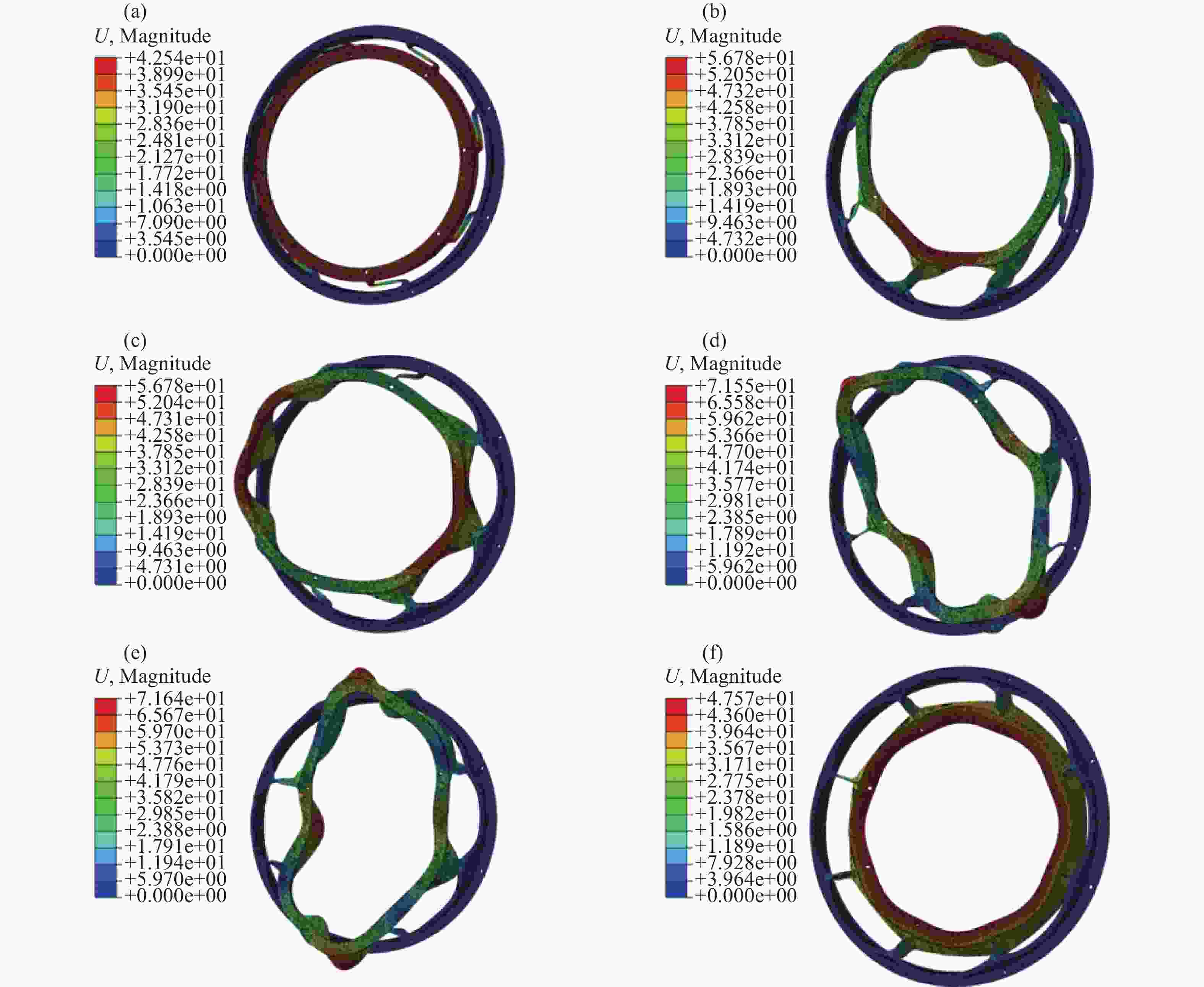
图 15 系统的前六阶模态振型
Figure 15. The first six modes of the system
表 3 系统的前六阶模态固有频率
Table 3. The first six modes natural frequencies of the system
Order Natural frequency/Hz First order 252.41 Second order 1400.20 Third order 1400.41 Fourth order 1707.10 Fifth order 1707.1 Sixth order 1769.51 由图15和表3可以看出,像旋补偿机构的固有频率满足系统的设计需求,像旋补偿机构具有较高的控制带宽,系统具有较高的控制精度。
-
对于大视场空间相机在成像期间所产生的像旋,首先对其进行定量分析,通过齐次坐标变换法计算相机所产生的像旋角度为±2′,为像旋补偿提供了技术指标;然后通过该技术指标设计了一套基于柔性单元的像旋补偿机构,建立了像旋补偿机构的数学模型,通过力学知识和卡氏第二定理推导了像旋补偿机构柔性单元的柔度矩阵和精度矩阵;并根据所推导的公式结合系统的应力和基频,通过遗传算法对柔性单元进行优化设计,得到像旋补偿机构的最优解;最后确定像旋补偿机构由八个直梁圆角柔性单元所连接的内外环组成,由两个对称布置的压电陶瓷驱动器提供驱动力,总动力为115 N时对相机进行±2′的像旋补偿,内环最大位移为77.5 μm,之后通过实验对系统进行了验证,根据实验结果可得,系统具有良好的线性度,且实验结果与仿真结果误差均小于5%,验证了系统的可靠性。通过有限元仿真验证了系统的应力和前六阶固有频率,均符合系统设计要求。
所推导的柔性单元的柔度矩阵和精度矩阵与柔性单元的优化设计方法对柔性单元的设计、分析和应用具有一定的参考价值。所设计的像旋补偿机构对大视场空间相机的像旋补偿,在消除像的同时避免了像移的出现,具有一定的工程价值,为像旋补偿机构的小型化、轻型化设计提供了新的思路。
Image rotation compensation mechanism of large field of view space camera and its optimization design
-
摘要: 在对空间碎片进行分析研究中,大视场的天基目标探测载荷成为提高探测效率的有效方式,在实际成像过程中,由于曝光时间长,加上卫星自身在轨姿态的运动、二维转台的转动等因素,会导致空间相机在图像上产生像旋。通过齐次坐标变换法对像旋进行分析,得出相机存在±2′的像旋,并利用柔性单元和压电驱动器设计了一种新型无摩擦、无磨损、免润滑的像旋补偿机构,带动空间相机反方向的旋转对像旋进行补偿。然后对柔性单元应力和系统固有频率进行优化设计,推导柔度公式和精度公式,并对结果进行有限元仿真分析。结果表明:仿真结果与理论计算模型的最大相对误差均小于 5% ,该机构能够实现大视场空间相机的像旋补偿,并且具有较高的精度。Abstract:
Objective Space-based target detection is the main way to observe space debris. In recent years, with the gradual increase of space debris, it is difficult for small field of view space cameras to meet the observation needs, and the use of large field of view space cameras is increasing. During the observation of space debris, due to the orbital motion of the satellite itself and the motion of the two-dimensional turntable, the image rotation will occur in the imaging of the large field of view space camera, especially when observing dim targets, the camera's exposure time will increase, and the generated image rotation will also increase. It seriously affects the accuracy of recognition and reduces the efficiency of large field of view space camera. Therefore, image rotation compensation must be carried out for large field of view space camera. Methods In order to determine the performance index of image rotation compensation, the imaging coordinate system of the system is established (Fig.1), and the image rotation of the system is calculated by the homogeneous coordinate change method. According to the performance index of image rotation compensation, a new type of image rotation compensation mechanism based on the inner and outer rings of symmetrical right straight circular flexure hinge is proposed (Fig.3). Then, the flexibility and accuracy formula of the flexible element of the image rotation compensation mechanism is deduced according to the second theorem of Cassegrain, and the relationship between the flexibility and the structure size is analyzed. Then, the image rotation compensation structure is optimized by genetic algorithm. Finally, the static and modal analysis of the image rotation compensation mechanism is carried out by simulation (Fig.11, 12, 14), and it is verified by experiments. Results and Discussions By analyzing and calculating the ± 2′ image rotation of a large field of view space camera, an image rotation compensation mechanism composed of eight completely symmetrical flexible elements is designed for the image rotation change. By analyzing it, the relationship between the flexibility and accuracy of the flexible element and the size of the flexible element is obtained (Fig.7-8). Through genetic algorithm, the final design size of the flexible element is t=0.5 mm, r=5.5 mm, w=18 mm, l=9 mm. The simulation analysis results show that the maximum displacement component in the plane is 77.5 μm. The error with theoretical calculation model is 1.79%, far less than 5%, which meets the design requirements of the system; The maximum stress is 65 MPa, which is far less than the allowable stress of 330 MPa, which meets the design requirements of the system. The image rotation compensation mechanism has high stability and safety. Through experimental verification, the experimental value and theoretical error of the image rotation compensation mechanism are also less than 5%, and the image rotation compensation mechanism has good linearity in the working range (Fig.14). The results of modal analysis (Tab.3) show that all modes of the system meet the design requirements. Conclusions For the image rotation generated by the large field of view space camera during imaging, the image rotation angle generated by the camera is calculated by the homogeneous coordinate transformation method to be ± 2′, and then a set of image rotation compensation mechanism based on the flexible element is designed by this technical index, the mathematical model of the image rotation compensation mechanism is established, and the flexibility matrix and precision matrix of the flexible element of the image rotation compensation mechanism are derived; Then, according to the derived formula and the stress and fundamental frequency of the system, the image rotation compensation mechanism is optimized by genetic algorithm. Finally, the image rotation compensation mechanism is determined to be composed of the inner and outer rings connected by 8 straight beam fillet flexible elements. When the total force is 115 N, the camera is compensated with ± 2′ image rotation, and the maximum displacement of the inner ring is 77.5 μm. Then the first six natural frequencies of the system are verified by the finite element simulation, which meet the system design requirements, and the system is verified by experiments. According to the experimental results, the system has good linearity, and the error between the experimental results and the simulation results is less than 5%, which verifies the reliability of the system. -
图 7 工作方向柔度与r、t的关系
Figure 7. Relationship between flexibility of working direction and r, t
图 10 (a) 优化后的像旋补偿机构;(b)像旋补偿机构有限元模型
Figure 10. (a) Optimized image rotation compensation mechanism; (b) Finite element model of image rotation compensation mechanism
图 13 像旋补偿机构的力-位移测试实验
Figure 13. Force-displacement test experiment of image rotation compensation
图 14 像旋补偿机构力-位移图
Figure 14. Force-displacement diagram of image rotation compensation mechanism
表 1 力-位移实验测试数据
Table 1. Test data of force-displacement experiment
Outside force/N First place Second place Third place Fourth place Average value/μm 15 13 12 13 13 12.75 30 20 20 21 20 20.25 45 29 28 29 31 29.25 60 39 39 39 37 38.50 75 47 47 48 49 47.75 90 59 57 57 58 57.75 105 68 67 68 66 67.25 120 76 78 77 79 77.50 135 87 86 88 87 87.00 150 98 97 97 95 96.75  下载: 导出CSV
表 2 力-位移实验测试数据与仿真数据对比
Table 2. Comparison of force-displacement test data and simulation data
Outside force/
NExperimental data/
μmSimulation data/
μmError 15 12.75 12.92 1.3% 30 20.25 20.22 0.16% 45 29.25 29.70 1.5% 60 38.50 39.33 2.1% 75 47.75 48.95 2.5% 90 57.75 58.74 1.7% 105 67.25 68.46 1.8% 120 77.50 78.19 0.88% 135 87.0 87.92 1.1% 150 96.75 97.50 0.78%
下载: 导出CSV
表 3 系统的前六阶模态固有频率
Table 3. The first six modes natural frequencies of the system
Order Natural frequency/Hz First order 252.41 Second order 1400.20 Third order 1400.41 Fourth order 1707.10 Fifth order 1707.1 Sixth order 1769.51
下载: 导出CSV
-
[1] 李明, 龚自正, 刘国青. 空间碎片监测移除前沿技术与系统发展[J]. 科学通报, 2018, 63(25): 2570-2591 doi: 10.1360/N972017-00880 Li Ming, Gong Zizheng, Liu Guoqing. Frontier technology and system development of space debris surveillance and active removal [J]. Chinese Science Bulletin, 2018, 63(25): 2570-2591. (in Chinese) doi: 10.1360/N972017-00880 [2] Wang Meizhu, Huang Xiaoxian, Feng Qi. Elimination method of image rotation for geostationary radiometer and its verification method [J]. Opto-Electronic Engineering, 2018, 45(5): 85-92. (in Chinese) [3] Wang D J, Li W M, Yao Y, et al. A fine image motion compensation method for the panoramic TDI CCD camera in remote sensing applications [J]. Optics Communications, 2013, 298: 79-82. [4] 周莘, 柴雄力, 邵枫. 基于网格形变的立体变焦视觉优化[J]. 光电工程, 2021, 48(04): 15-29. Zhou Shen, Chai Xiongli, Shao Feng. Stereoscopic zoom for visual optimization based on grid deformation [J]. Opto-Electronic Engineering, 2021, 48(4): 15-29. (in Chinese) [5] 郭新胜, 鱼云岐, 陈洪彩, 等. 光学消像旋高精度位置控制[J]. 兵工自动化, 2011, 30(07): 67-68+72 Guo Xinsheng, Yu Yunqi, Chen Hongcai, et al. Optical away like spin high-precision position control [J]. Ordnance Industry Automation, 2011, 30(7): 67-68, 72. (in Chinese) [6] 邱兆文, 宋利权, 张炳通. 四反射镜结构极坐标红外惯性稳像平台像旋研究(英文)[J]. 红外与激光工程, 2017, 46(12): 197-202. Qiu Zhaowen, Song Liquan, Zhang Bingtong. Research on the image rotation of the polar coordinates infraredinertial stable platform with four reflected mirrors [J]. Infrared and Laser Engineering, 2017, 46(12): 1217004. (in Chinese) [7] 王昱棠, 田大鹏. 航空光电成像像移与像旋运动补偿控制技术综述[J]. 光学精密工程, 2022, 30(24): 3128-3138. doi: 10.37188/OPE.20223024.3128 Wang Yutang, Tian Dapeng. Review of image shift and image rotation compensation control technology for aviation optoelectronic imaging [J]. Optics and Precision Engineering, 2022, 30(24): 3128-3138. (in Chinese) doi: 10.37188/OPE.20223024.3128 [8] 张继超, 周九飞, 张雷. 摆扫式航空遥感器像旋补偿方法[J]. 红外与激光工程, 2012, 41(09): 2396-2400 Zhang Jichao, Zhou Jiufei, Zhang Lei. Image spin compensation on scanning frame remote sensor [J]. Infrared and Laser Engineering, 2012, 41(9): 2396-2400. (in Chinese) [9] Lobontiu N, Paine J S N, Garcia E, et al. Corner-filleted flexure hinges [J]. Journal of Mechanical Design, 2001, 123(3): 346-352. doi: 10.1115/1.1372190 [10] Lobontiu N. In-plane compliances of planar flexure hinges with serially connected straight- and circular-axis segments [J]. Journal of Mechanical Design, 2014, 136(12): 122301. [11] Lobontiu N. Compliance-based modeling and design of straight-axis/circular-axis flexible hinges with small out-of-plane deformations [J]. Mechanism and Machine Theory, 2014, 80: 166-183. doi: 10.1016/j.mechmachtheory.2014.06.002 [12] Lobontiu N. Compliance-based matrix method for modeling the quasi-static response of planar serial flexure-hinge mechanisms [J]. Precision Engineering-Journal of the International Societies for Precision Engineering and Nanotechnology, 2014, 38(3): 639-650. [13] 于靖军, 郝广波, 陈贵敏, 等. 柔性机构及其应用研究进展[J]. 机械工程学报, 2015, 51(13): 53-68 doi: 10.3901/JME.2015.13.053 Yu Jingjun, Hao Guangbo, Chen Guimin, et al. State-of-art of compliant mechanisms and their applications [J]. Journal of Mechanical Engineering, 2015, 51(13): 53-68. (in Chinese) doi: 10.3901/JME.2015.13.053 [14] 吴松航, 董吉洪, 徐抒岩, 等. 快速反射镜椭圆弧柔性铰链多目标优化设计[J]. 红外与激光工程, 2021, 50(04): 187-195 Wu Songhang, Dong Jihong, Xu Shuyan, et al. Multi-objective optimal design of elliptic flexible hinge in fast steering mirror [J]. Infrared and Laser Engineering, 2021, 50(4): 20200286. (in Chinese) [15] 李林, 颜昌翔, 田海英, 等. 基于柔性铰链的像旋补偿机构设计与分析[J]. 济南大学学报(自然科学版), 2021, 35(02): 95-101 Li Lin, Yan Changxiang, Tian Haiying, et al. Design and analysis of image rotation compensation mechanism based on flexible hinges [J]. Journal of University of Jinan (Science and Technology), 2021, 35(2): 95-101. (in Chinese) [16] 胡春晖, 颜昌翔. 基于高斯光学齐次坐标变换的光机装调[J]. 光学精密工程, 2012, 20(11): 2353-2359 doi: 10.3788/OPE.20122011.2353 Hu Chunhui, Yan Changxiang. Optical-mechanical assembly based on Gaussian optical homogeneous coordinate transformation [J]. Optics and Precision Engineering, 2012, 20(11): 2353-2359. (in Chinese) doi: 10.3788/OPE.20122011.2353 [17] 颜昌翔, 王家骐. 航相机像移补偿计算的坐标变换方法[J]. 光学精密工程, 2000, (03): 203-207 Yan Changxiang, Wang Jiaqi. Method of coordinate transformation for IM & IMC calculation in aerospace camera system [J]. Optics and Precision Engineering, 2000, 8(3): 203-207. (in Chinese) [18] Wang Jiaqi, Jin Guang, Yan Changxiang. Orientation error analysis of airborneopto-electric tracking and measuring device [J]. Optics and Precision Engineering, 2005, 13(2): 105-116. (in Chinese) [19] Zhao Lei, Gong Yan, Hua Yangyang. Compliance matrix analysis of Corner-filleted flexure hinge [J]. China Mechanical Engineering, 2013, 24(18): 2462-2468. (in Chinese) [20] Chen G, Wang J, Liu X. Generalized equations for estimating stress concentration factors of various notch flexure hinges [J]. Journal of Mechanical Design, 2014, 136(3): 031009. doi: 10.1115/1.4026265 [21] Zhang Weifan, Yan Changxiang, Gao Zhiliang, et al. Optimal design of natural frequency of two-degree-of-freedomfast steering mirror system [J]. Infrared and Laser Engineering, 2021, 50(6): 20200450. (in Chinese) -

 点击查看大图
计量
- 文章访问数: 113
- HTML全文浏览量: 30
- PDF下载量: 30
- 被引次数: 0

