


-
目前,非球面光学元件在医疗、国防以及航空航天等各个领域有着广泛的应用。离轴非球面反射镜作为离轴光学系统的核心光学元件,具有缩小光学系统体积、增大视场、提高成像质量的作用[1-4]。铝合金材料由于其加工效率高、成本低、能够实现光学系统无热化一体设计,是离轴非球面反射镜常用的材料之一[5-6]。由于离轴光学系统所应用的领域特殊,对离轴非球面面形精度要求十分严格,因此,对离轴非球面铝合金反射镜的高精度加工技术研究很有必要。
单点金刚石车削(SPDT)技术由于其车削效率高、可以实现任意面型加工的特点[7-9],越来越受到研究人员的青睐,采用SPDT技术车削也是加工铝合金材料常用的方法之一。目前,国内外应用SPDT技术对离轴非球面铝合金反射镜进行超精密加工开展了大量研究:天津大学的张效栋等[10]提出了子母同体的离轴非球面超精密车削方法,通过补偿加工误差的方式对口径20 mm的铝合金反射镜进行加工,取得了面形精度PV为0.316λ的加工结果;国防科技大学的关朝亮等[11]在SPDT加工离轴非球面时,通过补偿刀具对中误差的方式,并对口径46 mm的铝合金反射镜进行加工,获得面形精度PV为1.07λ的加工精度;中国兵器工业集团的景海华等[12]采用坐标平移的方式对口径120 mm的离轴非球面铝合金反射镜进行SPDT车削,获得RMS为1/3λ的面形精度;德国Fraunhofer研究所的Gebhardt等[13]将离轴非球面反射镜作为自由曲面,应用慢刀伺服辅助SPDT加工的方式对口径250 mm的铝合金反射镜进行加工,得到面形精度PV为4.74λ的加工结果。采用SPDT技术加工大口径离轴非球面铝合金光学元件时,产生的制造误差包括刀具对中误差、车削轨迹误差、离心力误差,而对于加工大口径铝合金反射镜时,其离心力误差对面形精度产生的影响很大,对于这部分的研究却鲜有报道。
文中针对SPDT加工过程中由于离心力误差导致大口径离轴非球面反射镜面形精度变差的问题,提出了抑制离心力变形的加工方法。根据离心力产生的机理,建立了抑制离心力坐标变换加工模型。通过有限元仿真,分析了坐标变换过程中不同平移位移及旋转角度对面形精度的影响,并予以优化。最后,应用仿真分析得到的坐标变换参数对口径320 mm的RSA6061铝合金离轴非球面反射镜进行超精密车削实验,得到了RMS 0.198λ的高精度离轴非球面铝合金反射镜。所提出的抑制离心力变形的加工方法实现了大口径离轴非球面铝合金反射镜的超精密加工。在提高离轴非球面铝合金反射镜面形精度的同时,降低了离轴非球面铝合金反射镜在制造过程中口径、离轴量、矢高差对加工行程的限制,有效提高了铝合金光学元件的制造精度。
-
相对于球面而言,非球面只有一个对称轴,且曲率半径不同,而离轴非球面又增加了离轴量的限制,因此加工难度直线上升。离轴非球面作为非球面光学元件的一部分,对于确定的离轴非球面描述只需要描述出其非球面母镜,并给出相应的离轴量及口径。常用的非球面的表达式如下[14]:
$$ \begin{split} Z=&\frac{{c\left( {{x^2} + {y^2}} \right)}}{{1 + \sqrt {1 - \left( {k + 1} \right){c^2}\left( {{x^2} + {y^2}} \right)} }} +\\ &{B_1}{\left( {{x^2} + {y^2}} \right)^2} + {B_2}{\left( {{x^2} + {y^2}} \right)^4} + \cdots\cdots \end{split} $$ (1) 式中:c=1/R为顶点曲率,R为顶点曲率半径;k为二次曲面常数;B1、B2、······为高次项系数。为了更直观地体现出离轴量及口径,对公式(1)进行坐标变换:
$$ x = l\cos \theta + {X_0} $$ (2) $$ y = l\sin \theta + {Y_0} $$ (3) 式中:l为原点距离曲面的距离,l=1/2D,D为口径;X0、Y0分别为X方向与Y方向离轴量的分量,满足$ {{X}_{0}}^{2}+{{Y}_{0}}^{2}={H}^{2} $,H为离轴量。
将公式(2)、(3)代入公式(1)中可得包含离轴量及口径的非球面表达式为:
$$ \begin{split} Z=&\frac{{c\left( {{l^2} + {H^2} + 2l\left( {{X_0}\cos \theta + {Y_0}\sin \theta } \right)} \right)}}{{1 + \sqrt {1 - \left( {k + 1} \right){c^2}\left( {{l^2} + {H^2} + 2l\left( {{X_0}\cos \theta + {Y_0}\sin \theta } \right)} \right)} }} + \\ & {B_1}{\left( {{l^2} + {H^2} + 2l\left( {{X_0}\cos \theta + {Y_0}\sin \theta } \right)} \right)^2} + \\ & {B_2}{\left( {{l^2} + {H^2} + 2l\left( {{X_0}\cos \theta + {Y_0}\sin \theta } \right)} \right)^4} + \cdots\cdots \end{split} $$ (4) -
单点金刚石装置如图1所示,在加工过程中,工件随着C轴高速旋转,采用金刚石刀具作为切削工具沿Z轴方向移动,工件沿X轴方向进给,XZC三轴联动,实现光学元件的超精密车削加工。

图 1 单点金刚石车削实验示意图
Figure 1. Experimental diagram of SPDT
在加工过程中,随主轴旋转工件离心力加载,受到离心力作用,工件随离心力产生非线性弹性变形;当主轴旋转停止,离心力卸载,工件恢复变形前状态。由于离心力误差的存在,导致面形精度下降,图2为口径为280 mm$ \times $100 mm的长条形铝合金离轴非球面反射镜在未进行离心力误差修正情况下的加工结果[8]。
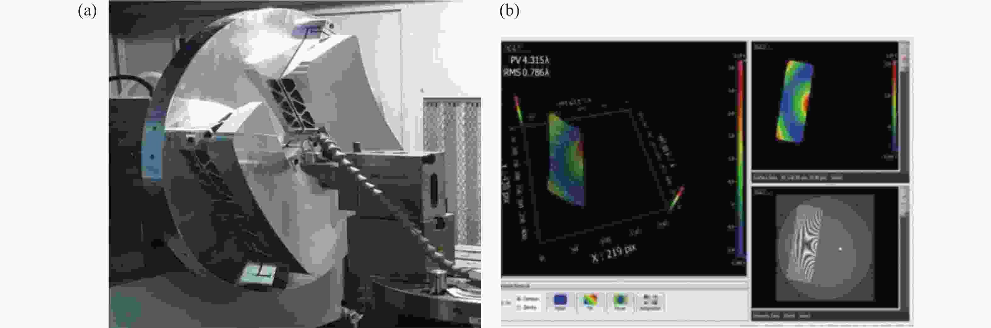
图 2 铝合金离轴非球面反射镜(a)加工过程及(b)加工结果
Figure 2. (a) Machining process and (b) processing results of aluminum alloy off-axis aspheric mirror
通过图2可以看出,离轴非球面反射镜面形精度PV值为4.315λ、RMS值为0.786λ。离心力误差的存在导致加工结果并不理想。离心力变形产生的过程如图3所示。

图 3 离心力变形过程。(a)初始毛坯面形;(b)离心力加载弹性变形;(c)车削过程;(d)离心力卸载弹性恢复
Figure 3. Centrifugal force deformation process. (a) Initial blank surface shape; (b) Centrifugal force loading elastic deformation; (c) Turning process; (d) Centrifugal force unloading elastic recovery
图3(a)表示在加工开始前,主轴尚未开始旋转,此时工件面形为接近设计值的毛坯;图3(b)表示开始加工,主轴开始旋转,随着主轴转速的增加,工件所受离心力不断增加,在离心力小于屈服应力前,材料保持弹性变形状态,其中虚线表示理想面形,实线表示实际面形;图3(c)表示加工过程中,受到离心力作用的情况下,刀具按照轨迹加工光学元件,当加工完成,在主轴停止转动前,此时光学元件的面形为设计面形;图3(d)表示加工完成后,主轴停止转动,离心力卸载,图中虚线为理想面形,实线为实际面形,由于离心力产生的弹性变形恢复,导致实际加工面形与理想面形存在偏差。
离心力变形是由离心力作用产生的,离心力的计算公式如下:
$$ \sigma {\text{ = }}\Delta m \cdot a = \frac{{\Delta m \cdot {\omega ^2} \cdot r}}{2} = \frac{{{\omega ^2} \cdot r}}{2} \cdot \rho \cdot S \cdot \Delta h $$ (5) 式中:$ \sigma $为离心力,N;$ \omega $为角速度,rad/s;$ r $为工件上微元与旋转中心距离,m;$ \rho $为密度,kg/m3;$ S $为面积,m2;$ \Delta h $为矢高,m。
本征模型是用来描述材料应力与应变之间关系的方式,文中采用Johnson-Cook本征模型,其表达形式如下:
$$ \sigma {\text{ = }}\left( {A + B{{\overline \varepsilon }_p}^n} \right)\left( {1 + C\ln {\varepsilon ^ * }} \right)\left( {1 - {T_H}^m} \right) $$ (6) 式中:A为参考应变率$ {\varepsilon }_{0} $和参考温度Troom下的材料初始屈服应力;B、n分别为参考应变率$ {\varepsilon }_{0} $和参考温度Troom下的材料应变硬化模量和硬化指数;C表示材料应变率强化参数;$ {\overline{\varepsilon }}_{p} $为有效塑性应变;m为材料热软化参数。
由公式(5)、(6)可知,离心力变形大小与加工光学元件口径成正比,对于大口径光学元件而言,离心力误差变得尤为显著。因此,在加工大口径光学元件时,需要通过有效的方式抑制离心力误差,提高面形精度。
-
由于离轴非球面是光轴与几何中心不重合的非回转对称光学元件,而伺服系统能够精准地控制刀具与工件之间的相对位置,因此,根据车削的加工特征以及离轴非球面的性质可以定义两种加工模型:一种为目前离轴非球面反射镜常用加工模型,即传统加工模型;另一种为所提出的抑制离心力坐标变换加工模型。两种加工模型如图4所示。
图4(a)为传统加工模型,即加工坐标系(OpXpY
p Zp)与母镜坐标系(OXYZ)重合。在传统加工模型下对离轴非球面进行加工时,仅能加工离轴量小、口径小、矢高差小的离轴非球面光学元件。为满足金刚石车床动平衡等要求,通常要同时加工多个离轴非球面光学元件;图4(b)为抑制离心力坐标变换加工模型,是对传统加工模型进行坐标变换,即加工坐标系与离轴非球面变换坐标系(OcX c Y c Z c )重合。所提出的抑制离心力坐标变换加工模型的主要目的是抑制车削过程中受离心力影响引起的面形误差,并且能够解决矢高差、口径以及离轴量等因素限制离轴非球面加工的问题。其坐标变换过程如下: 将非球面的离轴量完全设置在子午截面能够简化计算模型,即公式(4) 中X0=H,Y0=0。建立抑制离心力坐标变换加工模型首先要将离轴非球面进行平移,即将离轴非球面的变换坐标系中心平移到加工坐标系中心。如图4(b)需要将Oc点移动到Op点,需建立一个平移矩阵P。
$$ P = \left[ {\begin{array}{*{20}{c}} {{X_1}} \\ 0 \\ {{Z_1}} \end{array}} \right] $$ (7) 其次,将离轴非球面变换坐标系与加工坐标系重合,建立一个旋转矩阵R:
$$ R{\text{ = }}\left[ {\begin{array}{*{20}{c}} {\cos \alpha }&0&{ - \sin \alpha } \\ 0&1&0 \\ {\sin \alpha }&0&{\cos \alpha } \end{array}} \right] $$ (8) 式中:α为旋转角度。
由公式(7)、(8)可知,要得到在抑制离心力坐标变换加工模型下点(x1, y1, z1),只需要将母镜坐标系下离轴非球面上与之对应的点(x, y, z)进行如下变换:
$$ \left[ {\begin{array}{*{20}{c}} {{x_1}} \\ {{y_1}} \\ {{{\textit{z}}_1}} \end{array}} \right] = R\left[ {\begin{array}{*{20}{c}} x \\ y \\ {\textit{z}} \end{array}} \right] - P $$ (9) 通过公式(9)可得到在抑制离心力坐标变换加工模型下,离轴非球面直角坐标方程及柱坐标方程如下:
$$ {\textit{z}}\left( {x,y} \right) = {C_1}{C_2} - {C_2}\sqrt {{C_1}^2 - {C_2}\left[ {\left( {1 + k{{\sin }^2}\alpha } \right){x^2} + {y^2}} \right]} $$ (10) 式中: ${C_1} = \dfrac{R}{{\sqrt {1 + k{{\sin }^2}\alpha } }} - kx\sin \alpha \cos \alpha$; ${C_2} = \dfrac{1}{{1 + k{{\cos }^2}\alpha }}$。
$$ \begin{split} &{\textit{z}}\left( {r,\theta } \right) = {D_1} + {D_2}l\cos \theta - \\ &\sqrt {{D_1}^2 + 2{D_1}{D_2}l\cos \theta - {C_2}{l^2} + \left( {{D_2}^2 - \frac{{k{{\sin }^2}\alpha }}{{1 + k{{\cos }^2}\alpha }}} \right){l^2}{{\cos }^2}\theta } \end{split} $$ (11) 式中: ${D_1}=\dfrac{R}{{\left( {1 + k{{\cos }^2}\alpha } \right)\sqrt {1 + k{{\sin }^2}\alpha } }}$; ${D_2} = \dfrac{{ - k\sin 2\alpha }}{{2\left( {1 + k{{\cos }^2}\alpha } \right)}}$。
由公式(5)可知,离心力的大小与反射镜与旋转中心之间的距离和反射镜的矢高差成正比。在上述两种加工模型中,抑制离心力坐标变换加工模型能够明显降低离心力变形,提高加工精度。同时,平移位移以及旋转角度是影响反射镜与旋转中心之间距离和反射镜的矢高差根本因素。因此,要根据光学元件的离心力变形大小对平移位移以及旋转角度进行优化,进而保证离轴非球面光学元件高精度加工。

图 4 离轴非球面加工模型。(a)传统加工模型;(b)抑制离心力坐标变换加工模型
Figure 4. Off-axis aspheric processing model. (a) Traditional processing model; (b) Suppression centrifugal force coordinate transformation machining model
-
抑制离心力坐标变换加工模型的平移位移以及旋转角度的选取对能否实现抑制离心力变形至关重要。为抑制离心力变形对离轴非球面铝合金反射镜进行坐标变换,以表1所示离轴非球面参数为例进行仿真分析。
表 1 离轴非球面参数
Table 1. Off-axis aspheric surface parameters
k R/mm D/mm H/mm B1,B2,··· −0.998578576 1968.080 320 600 0 由离心力变形具有非线性,因此采用有限元分析的方式逐步增加载荷,在关键部分用最小二分法获得实现离心力变形最小的坐标变换方式。分析过程中应用RSA6061铝合金作为离轴非球面反射镜材料,其Johnson-Cook本征模型如表2所示[15]。
表 2 6061铝合金材料Johnson-Cook本征模型
Table 2. Johnson-Cook intrinsic model of 6061 aluminum alloy material
ρ/kg·m–3 $ v $ A/MPa B/MPa n C m ${C}_{p}/{\rm{J} }\cdot { {\rm{kg} } }^{-1}\cdot { {\rm{K} } }^{-1}$ 2700 0.33 110 256 0.34 0.015 1.0 896 为了验证采用抑制离心力坐标变换加工模型对离轴非球面铝合金光学元件加工时的离心力变形的抑制情况,应用ANSYS Workbench有限元仿真软件,在相同工艺参数下对表1所示的离轴非球面铝合金反射镜在SPDT加工过程中离心力变形进行仿真。在应用抑制离心力坐标变换加工模型进行加工时,坐标变换的平移位移和旋转角度不同产生的离心力变形大小不同,设置X轴方向平移位移为300~700 mm(Z方向根据非球面方程同时平移),旋转角度为14°~20°,仿真过程如图5所示。
图6详细描述了在不同平移位移及旋转角度的情况下,离轴非球面铝合金反射镜受到离心力变形产生的面形误差的大小。

图 5 离心力变形仿真过程
Figure 5. Simulation process of centrifugal force deformation
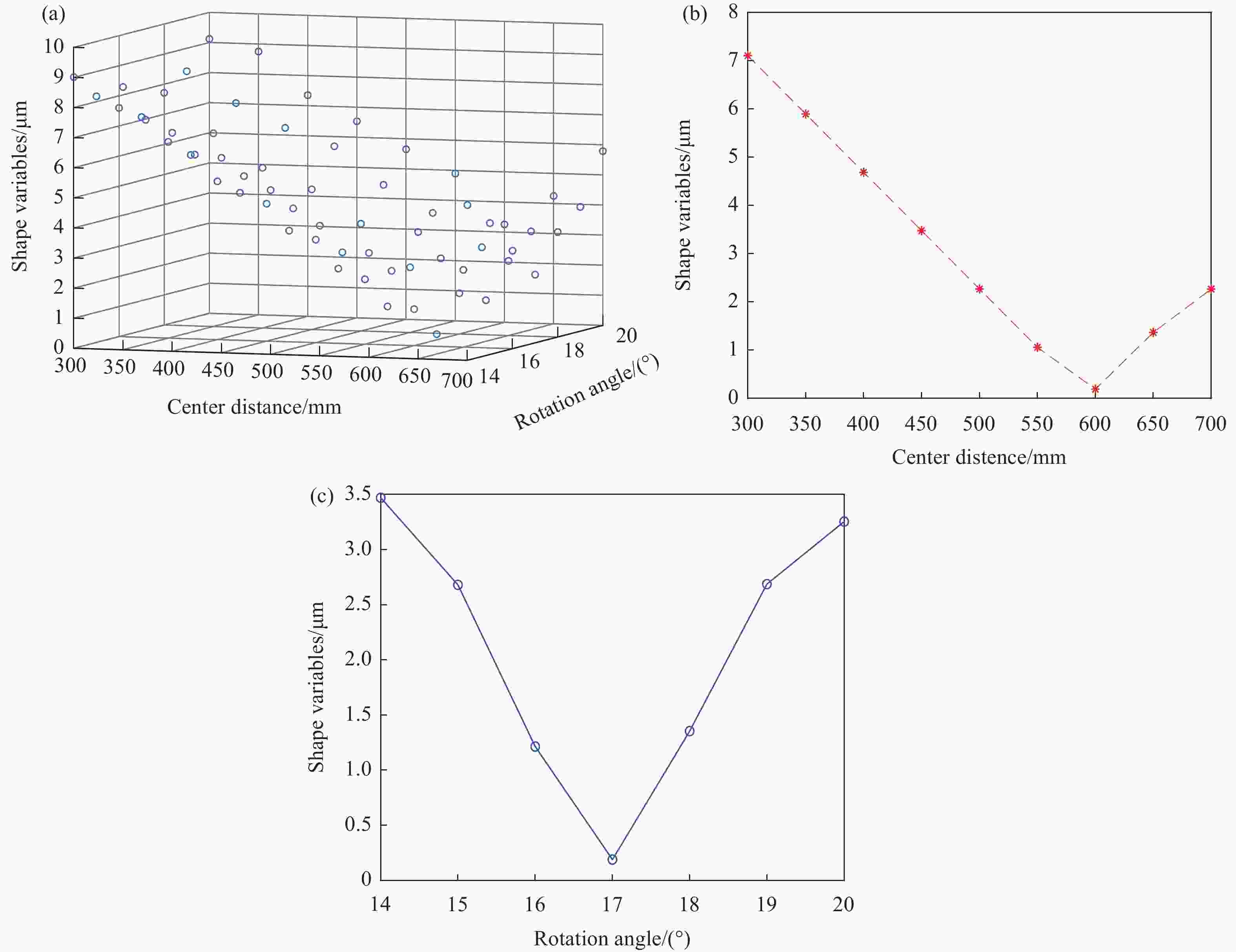
图 6 离心力变形仿真结果。(a)仿真结果;(b)最低点X-Y截面;(b)最低点Z-Y截面
Figure 6. Simulation results of centrifugal force deformation. (a) Simulation result; (b) The lowest point X-Y cross section; (b) The lowest point Z-Y cross section
图6(a)中,X方向表示抑制离心力坐标变换加工模型的平移位移,Y方向表示离心力变形的大小,Z方向表示抑制离心力坐标变换加工模型的旋转角度。通过多组仿真结果可以发现,当平移位移和旋转角度不同时,离心力变形的大小不同,且离心力变形的大小存在最高点和最低点。最高点值的大小为9.102 μm,最低点值的大小为0.189 μm,最小值仅为最大值的2%;对图6(a)中最低点选取两个截面如图6(b)和图6(c)所示。图6(b)中,横坐标代表抑制离心力坐标变换加工模型的平移位移,纵坐标代表离心力变形的大小。当平移位移增加时,离心力变形先减小后增加,存在极小值,由此可知最佳平移位移为600 mm。图6(c)中,横坐标代表抑制离心力坐标变换加工模型的旋转角度,纵坐标代表离心力变形的大小。随着旋转角度的变化,离心力变形先变小后增加,也存在极小值点,因此最佳旋转角度为17°。由此可见,在SPDT加工离轴非球面铝合金反射镜时,通过控制抑制离心力坐标变换加工模型的平移位移、旋转角度的方法进行车削加工,能够有效抑制离心力变形,提高面形精度。图7展示了表1所示的离轴非球面在传统加工模型与抑制离心力坐标变换加工模型下的面形形态。

图 7 离轴非球面面形形态。(a)传统加工模型;(b) 抑制离心力坐标变换加工模型
Figure 7. Off-axis aspheric surface morphology. (a) Traditional processing model; (b) Suppression centrifugal force coordinate transformation machining model
-
通过上述模型与理论分析,离轴非球面铝合金反射镜在抑制离心力坐标变换加工模型下加工精度受平移位移与旋转角度的影响。为了确保加工精度,综合考虑了抑制离心力坐标变换加工模型的平移位移和旋转角度对离轴非球面反射镜面形精度的影响。根据图6的仿真结果,可以得到能够有效抑制离心力变形的平移位移和旋转角度:平移位移为600 mm;旋转角度为17°。采用Nanoform 700 ultra 金刚石车床对表1所示参数的RSA6061铝合金离轴非球面进行超精密加工,具体加工参数如表3所示,并使用Zygo干涉仪对面形精度进行检测。
表 3 SPDT加工参数
Table 3. Processing parameters of SPDT
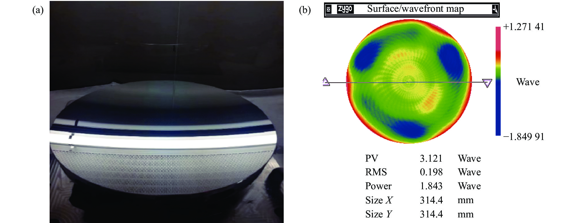
Parameter Value Feed rate/μm·rev–1 3 Spindle speed/r·min–1 180 Depth of cut/μm 3 Tool radius/mm 0.95 Materials RSA6061 离轴非球面铝合金反射镜实物图和检测结果分别如图8(a)、(b)所示。从图8(b)可以看出,对于口径为320 mm的铝合金反射镜,采用抑制离心力坐标变换加工模型的加工方法,有效提高了大口径离轴非球面铝合金反射镜的车削精度,也为后续其他材料的车削提供了基础依据。

图 8 离轴非球面铝合金(a)实物图及(b)检测结果
Figure 8. (a) Physical map and (b) test result of off-axis aspheric surface aluminum alloy
-
文中以实现大口径离轴非球面铝合金反射镜超精密加工为目标,根据离轴非球面反射镜在单点金刚石车削过程中产生离心力变形的机理,提出了抑制离心力变形的加工方法。以离轴非球面反射镜面形精度作为限制条件,通过有限元仿真的方法对抑制离心力坐标变换加工模型的平移位移和旋转角度进行优化,并验证了离轴非球面反射镜应用抑制离心力坐标变换加工模型加工的方法的有效性。在抑制离心力坐标变换加工模型的指导下,对口径320 mm的RSA6061铝合金离轴非球面反射镜进行加工,获得了PV为3.121λ、RMS 0.198λ的高精度离轴非球面铝合金反射镜。上述加工方式为大口径离轴非球面铝合金反射镜的超精密加工提供了理论指导,也为其他材料的大口径车削提供了理论支撑。
Turning method for correcting centrifugal force error of large-diameter off-axis aspheric surface
-
摘要: 大口径离轴非球面反射镜进行高精度车削过程中,由离心力引起的微米级面形误差变得尤为重要。为了减小离轴非球面反射镜在车削过程中受离心力变形而引起的面形误差,对离轴非球面铝合金反射镜开展了单点金刚石车削工艺研究。通过分析离心力产生机理,构建了抑制离心力坐标变换加工模型;利用有限元仿真的方法优化了坐标变换的平移位移和旋转角度,最后基于优化结果对口径320 mm的RSA6061铝合金离轴非球面反射镜进行车削实验,获得了面形精度为RMS 0.198λ(λ=632.8 nm)的离轴非球面铝合金反射镜,验证了该优化加工方法的有效性。上述优化方式能够显著提高单点金刚石车削加工大口径离轴非球面反射镜的加工精度。Abstract:
Objective As the core optical element of the off-axis optical system, the off-axis aspheric mirror has the function of reducing the volume of the optical system, increasing the field of view and improving the imaging quality. Aluminum alloy material is one of the commonly used materials for off-axis aspheric mirrors because of its high processing efficiency, low cost and the ability to realize the athermalized design of the optical systems. Due to the special application field of the off-axis optical system, the accuracy requirements of the off-axis aspheric surface are very strict. In the process of high-precision turning of large-diameter off-axis aspheric aluminum alloy mirrors, the micron-level surface shape error caused by centrifugal force becomes non-negligible. In order to reduce the surface shape error caused by centrifugal force deformation of off-axis aspheric aluminum alloy mirror during turning, it is necessary to study the single-point diamond turning process of off-axis aspheric aluminum alloy mirror. Methods Based on the basic principle of centrifugal force generation, a machining method to suppress centrifugal force error is proposed (Fig.4). Through the finite element simulation method, the translation displacement and rotation angle of the centrifugal force coordinate transformation machining model are optimized. Taking an off-axis aspheric aluminum alloy mirror with an aperture of 320 mm as an example, the optimal coordinate transformation parameters are reflected in the optimization results (Fig.6), and the off-axis aspheric mirror is used for ultra-precision turning. Results and Discussions Using the processing method of suppressing centrifugal force error, the off-axis aspheric surface of aluminum alloy with a diameter of 320 mm is processed by Nanoform 700 ultra diamond lathe, and the processing results are detected by Zygo interferometer. A high-precision off-axis aspheric aluminum alloy mirror with PV of 3.121λ and RMS of 0.198λ (Fig.8) is obtained. The machining method of surface suppression centrifugal force error can provide theoretical guidance for the ultra-precision machining of large-aperture off-axis aspheric aluminum alloy mirror, and provide theoretical support for the large-aperture turning of other materials. Conclusions Aiming at the problem that the surface shape accuracy of large-aperture off-axis aspheric mirror is deteriorated due to the centrifugal force error in single-point diamond turning process, a machining method to suppress centrifugal force deformation is proposed. According to the mechanism of centrifugal force generation, a machining model for suppressing centrifugal force coordinate transformation is established. The influence of different translation displacements and rotation angles on the surface shape accuracy in the process of coordinate transformation is analyzed and optimized by finite element simulation. Finally, the ultra-precision turning experiment of RSA6061 aluminum alloy off-axis aspheric mirror with an aperture of 320 mm is carried out by using the coordinate transformation parameters obtained by the simulation analysis, and a high-precision off-axis aspheric aluminum alloy mirror with RMS of 0.198λ is obtained. The proposed processing method of suppressing centrifugal force deformation realizes the ultra-precision machining of large-diameter off-axis aspheric aluminum alloy mirrors. While improving the surface shape accuracy of the off-axis aspheric aluminum alloy mirror, the limitation of the aperture, off-axis amount and vector height difference on the processing stroke in the manufacturing process of the off-axis aspheric aluminum alloy mirror is reduced, and the manufacturing accuracy of the aluminum alloy optical element is effectively improved. -
图 2 铝合金离轴非球面反射镜(a)加工过程及(b)加工结果
Figure 2. (a) Machining process and (b) processing results of aluminum alloy off-axis aspheric mirror
图 3 离心力变形过程。(a)初始毛坯面形;(b)离心力加载弹性变形;(c)车削过程;(d)离心力卸载弹性恢复
Figure 3. Centrifugal force deformation process. (a) Initial blank surface shape; (b) Centrifugal force loading elastic deformation; (c) Turning process; (d) Centrifugal force unloading elastic recovery
图 4 离轴非球面加工模型。(a)传统加工模型;(b)抑制离心力坐标变换加工模型
Figure 4. Off-axis aspheric processing model. (a) Traditional processing model; (b) Suppression centrifugal force coordinate transformation machining model
图 6 离心力变形仿真结果。(a)仿真结果;(b)最低点X-Y截面;(b)最低点Z-Y截面
Figure 6. Simulation results of centrifugal force deformation. (a) Simulation result; (b) The lowest point X-Y cross section; (b) The lowest point Z-Y cross section
图 7 离轴非球面面形形态。(a)传统加工模型;(b) 抑制离心力坐标变换加工模型
Figure 7. Off-axis aspheric surface morphology. (a) Traditional processing model; (b) Suppression centrifugal force coordinate transformation machining model
图 8 离轴非球面铝合金(a)实物图及(b)检测结果
Figure 8. (a) Physical map and (b) test result of off-axis aspheric surface aluminum alloy
表 1 离轴非球面参数
Table 1. Off-axis aspheric surface parameters
k R/mm D/mm H/mm B1,B2,··· −0.998578576 1968.080 320 600 0  下载: 导出CSV
表 2 6061铝合金材料Johnson-Cook本征模型
Table 2. Johnson-Cook intrinsic model of 6061 aluminum alloy material
ρ/kg·m–3 $ v $ A/MPa B/MPa n C m ${C}_{p}/{\rm{J} }\cdot { {\rm{kg} } }^{-1}\cdot { {\rm{K} } }^{-1}$ 2700 0.33 110 256 0.34 0.015 1.0 896
下载: 导出CSV
表 3 SPDT加工参数
Table 3. Processing parameters of SPDT
Parameter Value Feed rate/μm·rev–1 3 Spindle speed/r·min–1 180 Depth of cut/μm 3 Tool radius/mm 0.95 Materials RSA6061
下载: 导出CSV
-
[1] 孟庆宇. 三镜反射式光学系统综述(特邀) [J]. 红外与激光工程, 2022, 51(1): 20210986. Meng Qingyu. Overview of three-mirror reflective optical system (Invited) [J]. Infrared and Laser Engineering, 2022, 51(1): 20210986. (in Chinese) [2] 李庆林, 蔡媛媛, 张志飞, 等. 立式三反离轴相机光机结构设计[J]. 红外与激光工程, 2022, 51(10): 20220303. Li Qinglin, Cai Yuanyuan, Zhang Zhifei, et al. Opto-mechanical structure design of vertical off-axis TMA system camera [J]. Infrared and Laser Engineering, 2022, 51(10): 20220303. (in Chinese) [3] Xue Qingsheng, Bai Yang, Tian Zhongtian, et al. Spaceborne limb hyperspectral imager for ozone profile detection [J]. Opt Express, 2019, 27: 31348-31361. [4] 孙永雪, 夏振涛, 姜守望, 等. 可见光全天时遥感相机光学系统设计[J]. 红外与激光工程, 2020, 49(1): 0114003-0114003(6). Sun Yongxue, Xia Zhentao, Jiang Shouwang, et al. Optical system design of remote sensing camera with visible light all-day [J]. Infrared and Laser Engineering, 2020, 49(1): 0114003. (in Chinese) [5] Xu Sihua, Peng Xioaqiang, Tie Guipeng, et al. Athermalization of an optical system based on lens shape and assembly method [J]. Curr Opt Photon, 2019, 3: 429-437. [6] Vukobratovich D, Schaefer J P. Large stable aluminum optics for aerospace applications [C]//Proc SPIE, 2011, 8125: 81250T. [7] Oschmann J M, Clampin M, Fazio G G, et al. A study on ultra-precision machining technique for Al6061-T6 to fabricate space infrared optics [C]//SPIE Astronomical Telescopes + Instrumentation. International Society for Optics and Photonics, 2014, 9143: 91434Z. [8] 张继真. 铍铝合金反射镜设计和制造技术研究[D]长春: 中国科学院长春光学精密机械与物理研究所, 2019. Zhang Jizhen. Study on the design and manufacturing technologies of beryllium-aluminium mirror [D]. Changchun: Changchun Institute of Optics, Fine Mechanics and Physics, Chinese Academy of Sciences, 2019. (in Chinese) [9] Zhu Linlin, Li Zexiao, Fang Fengzhou, et al. Review on fast tool servo machining of optical freeform surfaces [J]. Int J Adv Manuf Technol, 2017, 95: 2071-2092. [10] 张效栋, 房丰洲, 魏桂爽, 等. 离轴非球面镜子母同体超精密车削加工法[J]. 机械科学与技术, 2010, 29(11): 1438-1442. Zhang Xiaodong, Fang Fengzhou, Wei Guishuang, et al. Ultra-precision turning using same-body method for off-axis aspheric mirror [J]. Mechanical Science and Technology for Aerospace Engineering, 2010, 29(11): 1438-1442. (in Chinese) [11] 关朝亮, 戴一帆, 尹自强. 刀具对中误差对离轴抛物面镜慢刀伺服车削加工的影响[J]. 纳米技术与精密工程, 2011, 9(01): 89-94.2011. 017. Guan Chaoliang, Dai Yifan, Yin Zoqiang. Effect of tool centering error on slow tool servo turning for off-axis parabolic mirrors [J]. Nanotechnology and Precision Engineering, 2011, 9(1): 89-94. (in Chinese) [12] 景海华, 王朔, 颜刘兵, 等. 一种铝合金离轴抛物面镜的制造[J]. 国防制造技术, 2019(54): 31-35. [13] Gebhardt A, Beier M, Scheiding S, et al. Fabrication method for large off-axis aspherical metal mirrors [C]//14th International Conference & Exhibition of the European Society of Precision Engineering and Nanotechnology, Dubrovnik, Croatia, 2014: 2-6. [14] 彭利荣, 程强, 曾雪锋, 等. 高次离轴凸非球面反射镜组合加工(特邀)[J]. 红外与激光工程, 2022, 51(9): 20220611. doi: 10.3788/IRLA20220611 Peng Lirong, Cheng Qiang, Zeng Xuefeng, et al. Combined fabrication of high order off-axis convex aspheric mirror (invited) [J]. Infrared and Laser Engineering, 2022, 51(9): 20220611. (in Chinese) doi: 10.3788/IRLA20220611 [15] 辛春亮, 薛再清, 涂建, 等. 有限元分析常用材料参数手册[M]. 北京: 机械工业出版社, 2019. -

 点击查看大图

计量
- 文章访问数: 150
- HTML全文浏览量: 32
- PDF下载量: 28
- 被引次数: 0

