


-
横向激励大气压(Transversely Excited Atmospheric, TEA) CO2激光器工作在9~11 μm的长波红外波段,许多有害气体及污染物的气溶胶在该波段范围有强烈的吸收,如NH3、SF6等,因此TEA CO2激光器被广泛用于环境探测激光雷达光源[1-4]。由于大气湍流的存在,一般需要在数十毫秒内的“大气冻结”时间内,通过发射对应探测物质的吸收峰-吸收谷谱线对,实现高灵敏度差分探测。而单台脉冲CO2激光器常采用的光栅选线结构难以在上述很短的时间内进行切换,因此采用双路交替发射谱线对的方式成为更优的选择。国内外均开展了相关的双光路TEA CO2激光器的研究。1979年,N.Menyuk等[1-2]研制了单台小型TEA CO2激光器,可输出谱线50条,重复频率500 Hz,最大脉冲能量大于20 mJ,并在1982年将两台该型激光器成功用于差分吸收激光雷达并在2.7 km实现对联氨和偏二甲肼等的探测。2007年,曲彦臣等[5]研制了一台车载、采用扫描振镜的双通道折叠腔CO2激光器,可输出谱线80条。2010年,Hasan Kariminezhad等[3]报道了采用双路TEA CO2激光器的激光雷达实现了SF6及其同位素的探测。2015年,郑义军等[6]报道的双路快调谐CO2激光器可输出谱线大于70条,并被用于差分吸收激光雷达实现了5 km的探测距离[4]。2022年,潘其坤等报道了可用于激光雷达探测的机械调Q紧凑型脉冲 CO2 激光器,实现了峰值功率3.7 kW、波长范围9.2~10.7 μm的调谐输出[7]。
CO2激光器气体放电工作时,热效应会不可避免地引起元器件温度的升高,进而可能影响激光器的光斑分布、指向性、输出光功率等。进入21世纪后,向大功率方向发展的CO2激光器被广泛应用于激光雷达和激光加工等领域,研究者们围绕热效应的影响开展了大量的研究[8-14],多数采用了有限元理论以分析千瓦级光功率激光器或激光设备中窗口镜的热形变所带来的影响,也提出了形变补偿和热交换等解决方案[12-13]。而对激光器腔体而言,由于其体积较大、热容较大以及采用了水冷等辅助散热方式的综合原因,其热形变一般不予考虑。近年来,由于激光雷达等领域的需求推动,TEA CO2激光器继续拓展了以小体积、低功率、高光束质量为目标的发展方向,因此热效应转而体现在紧凑空间的局部加热引起的腔体形变问题,并成为该方向工程难点之一。
目前已报道的有关紧凑型TEA CO2激光器谐振腔稳定性的研究较少[15],对其内部的热力形变过程也鲜有较为详细的讨论。文中搭建了一套可用于激光雷达探测的紧凑型双路TEA CO2激光装置,开展了对谐振腔的热稳定分析,提出了相应的热形变解决方法。
-
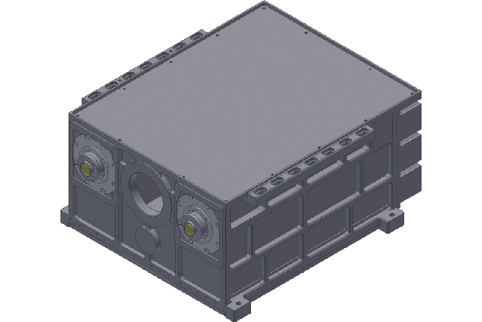
双路脉冲CO2激光器包含两路平行且独立的谐振腔,如图1所示,分别是左侧1#激光器和右侧2#激光器。装置总尺寸约为480 mm×370 mm×220 mm,左侧的激光头标记为1#通道,右侧的标记为2#通道。每套激光系统由密封的腔体(包括工作气体、主放电单元)、谐振腔以及正下方的高压模块构成。其中密封腔体的容积约2 L,增益尺寸约9 mm×9 mm×400 mm。主放电单元包含一套放电电极和电晕预电离装置,工作电压默认21 kV。每路谐振腔采用平凹腔设计,包含一块设置于装置前端的耦合率90%的输出镜,以及一块以Littrow方式工作$ d = 1/120{\text{ mm}} $的平面闪耀光栅,其中光栅由高精度伺服电机驱动旋转以选择工作波长,伺服电机悬挂安装于装置另一端。控制单元进行了整合并放置于装置的中间底部区域。激光器的主要输出参数见表1。

图 1 双光路TEA CO2激光器外形图
Figure 1. Outline of dual-path TEA CO2 laser
表 1 双通道激光的主要输出参数
Table 1. Main parameters of dual path
Parameter Numerical value Pulse energy for strong line/mJ >50 Pulse energy for weak line/mJ >10 Pulse width (full width at half maximum)/ns 60-150 Repetition rate/Hz 1 Minimum aperture (near grating)/mm 8 Beam divergence/mrad <4 Transverse mode TEM00 & TEM01 Number of output lines 70 -
1) 温度场分布
对于微元体${\rm{d}}x{\rm{d}}y{\rm{d}}{\textit{z}}$,根据能量守恒定律,输入的能量加上自身产生的热量应等于输出的能量。其导热微分方程可表示为:
$$ \frac{{{\partial ^2}T}}{{\partial {x^2}}} + \frac{{{\partial ^2}T}}{{\partial {y^2}}} + \frac{{{\partial ^2}T}}{{\partial {{\textit{z}}^2}}}{\text{ + }}\frac{{{q_{self}}}}{{k{\rm{d}}x{\rm{d}}y{\rm{d}}{\textit{z}}}} = \frac{1}{\alpha } \times \frac{{\partial T}}{{\partial t}} $$ (1) 式中:$k$为材料热导率;${q_{self}}$为微元体自身产热速率;$\alpha {\text{ = }}\dfrac{k}{{\rho c}}$为热扩散系数;$\;\rho $为热流密度分布;$c$为比热容。
通过将导热方程与三类边界条件相结合,分别是第一类边界条件—给定边界上任何时刻$t$的温度分布、第二类边界条件—热流密度分布$\;\rho $、第三类边界条件—周围流体的表面换热系数及流体温度${T_f}$,可得温度场的泛函表达式为[16]:
$$ \begin{split} J = & \int_V {\left\{ {\frac{1}{2}\left[ {{k_x}{{\left( {\frac{{\partial T}}{{\partial x}}} \right)}^2} + {k_y}{{\left( {\frac{{\partial T}}{{\partial y}}} \right)}^2} + {k_{\textit{z}}}{{\left( {\frac{{\partial T}}{{\partial {\textit{z}}}}} \right)}^2}} \right]} \right.} - \left. {\left( {q - \rho c\frac{{\partial T}}{{\partial t}}} \right)T} \right\}{\rm{d}}V + \\ & \int_{{S_2}} {qT{\rm{d}}{s_2}} + \int_{{S_3}} {\alpha \left( {\frac{1}{2}{T^2} - T{T_f}} \right){\rm{d}}{s_3}}\\[-10pt] \end{split} $$ (2) 式中:${k_x},{k_y},{k_{\textit{z}}}$为材料的热导率;$q = - kA\dfrac{{\partial T}}{{\partial x}}$为热传导速率;A为散热面积;$\;\rho c\dfrac{{\partial T}}{{\partial t}}$为单位体积热能的变化率。再通过设定温度插值函数:
$$ T = \left[ N \right]{\left\{ T \right\}^e} = {N_1}{T_1} + {N_2}{T_2} + \cdots + {N_p}{T_p} $$ (3) 上式中${N_i}\left( {i = 1,2, \cdots ,p} \right)$为形函数且满足$\displaystyle\sum {{N_i}} = 1$,${T_i}\left( {i = 1,2, \cdots ,p} \right)$为节点温度。温度场泛函表示为$J = J\left( {{T_1},{T_2}, \cdots {T_n}} \right)$,求解:
$$ \frac{{\partial J}}{{\partial {{\left\{ T \right\}}^e}}} = {\left[ {{K_1}} \right]^e}{\left\{ T \right\}^e} + {\left[ {{K_2}} \right]^e}{\left\{ T \right\}^e} + {\left[ {{K_3}} \right]^e}{\left\{ {\dot T} \right\}^e} - {\left\{ P \right\}^e} = 0 $$ (4) 则温度场的有限元方程为:
$$ \left( {\left[ {{K_1}} \right] + \left[ {{K_2}} \right]} \right)\left\{ T \right\} + \left[ {{K_3}} \right]\left\{ {\dot T} \right\} = \left\{ P \right\} $$ (5) 式中:$\dot T{\text{ = }}\dfrac{{\partial T}}{{\partial t}}$;$\left[ {{K_1}} \right]$和$\left[ {{K_2}} \right]$分别为传导和对流的贡献;$\left[ {{K_3}} \right]$为热容的贡献;$\left\{ P \right\}$为热载荷。
2) 热形变分布
在求解温度场的分布后,每个节点会受到温度的影响产生节点力,从而形成节点力的分布。根据虚功原理,节点力在节点虚位移上做的虚功等于应力在虚应变上做的虚功[16-17]:
$$ {\left\{ {{\delta ^{\text{*}}}} \right\}^{eT}}{\left\{ R \right\}^e} = \iiint {{{\left\{ {{\delta ^*}} \right\}}^{eT}}{{\left[ B \right]}^T}\left( {\left[ D \right]\left[ B \right]{{\left\{ \delta \right\}}^e}} \right.}\left. { - \left[ D \right]\left\{ {{\varepsilon _0}} \right\}} \right){\rm{d}}V $$ (6) 式中:$ {\left\{ {{\delta ^{\text{*}}}} \right\}^{eT}} $为虚应变;$ {\left\{ R \right\}^e} $为节点力。
$$ \left[ B \right] = \left[ {\begin{array}{*{20}{c}} {\dfrac{{\partial {N_1}}}{{\partial x}}}&{\dfrac{{\partial {N_2}}}{{\partial x}} \cdots \dfrac{{\partial {N_P}}}{{\partial x}}} \\ {\dfrac{{\partial {N_1}}}{{\partial y}}}&{\dfrac{{\partial {N_2}}}{{\partial y}} \cdots \dfrac{{\partial {N_P}}}{{\partial y}}} \\ {\dfrac{{\partial {N_1}}}{{\partial {\textit{z}}}}}&{\dfrac{{\partial {N_2}}}{{\partial {\textit{z}}}} \cdots \dfrac{{\partial {N_P}}}{{\partial {\textit{z}}}}} \end{array}} \right] $$ (7) $$ \left[ D \right] = \left[ {\begin{array}{*{20}{c}} {{k_x}}&0&0 \\ 0&{{k_y}}&0 \\ 0&0&{{k_{\textit{z}}}} \end{array}} \right] $$ (8) $$ \left\{ {{\varepsilon _0}} \right\}{\text{ = }}\alpha \Delta T\left\{ {\begin{array}{*{20}{c}} 1 \\ 1 \\ 1 \\ 0 \\ 0 \\ 0 \end{array}} \right\} $$ (9) 则有
$$ {\left\{ R \right\}^e} = - \alpha {\left[ B \right]^T}\left[ D \right]\frac{\Delta }{3}\left( {{T_i} + {T_j} + {T_m}} \right)\left\{ {\begin{array}{*{20}{c}} 1 \\ 1 \\ 1 \\ 0 \\ 0 \\ 0 \end{array}} \right\} $$ (10) 式中:$\Delta $为三角形微元的面积;Ti, Tj, Tm为温度节点。
3) 紧凑型双路激光器特点
双路激光器装置结构内包含着水平方向对称的多点分散热源。主要热源的基本功率参数见表2。
热源能够使其附近环境气体温度上升,作用方式分为两类,其一是放电直接产生废热,其二是器件发热。对于后者,文中主要考虑元器件主要以对流换热的形式传递热量,而忽略其与腔体的直接热传导。这是因为器件和腔体采用了点接触连接的方式,加上连接路径上有较多的低导热系数材料,如尼龙、环氧纤维板等,因此路径上热传导的效率较低。
表 2 热源参数(单位:W)
Table 2. Parameters of heat sources (Unit: W)
Parameter Numerical value Gas discharging (each path) 3.5 Servo motor (each path) 7.5 High voltage power supply (each path) 30 Control unit (common) 5 气体温度上升后,通过对流换热均匀地加热附近的舱室内壁,舱室内壁再以热传导的形式将热量逐渐传递至整个设备腔体外壳,并最终与环境以对流换热的形式达到热平衡。
因此文中在上述热传递形式的基础上开展对紧凑型TEA CO2激光器腔体温度场分布和形变量分布的分析和计算,研究角度不同于在大功率激光器中对窗口镜开展热形变分析。为简化计算模型,输入条件是添加对若干个热源附近内壁的热传导(仿真软件中记为Heat Flow),用来描述各热源对所在舱室内壁的均匀加热作用,也针对不同散热条件下的效果差异,调整了不同表面的对流换热系数(Convection)设置及环境温度(Ambient Temperature)等。
-
首先在4~30 ℃环境温度范围用指示光测试了硒化锌耦合输出镜、光栅(包括搭载光栅的伺服电机)的指向稳定性,实验表明其形变量是微小可忽略的。在此基础上,文中研究了因腔体热形变引起的输出镜安装基准面以及伺服电机安装基面的角度变化。
所有热源包括高压电源被密封在独立的舱室内,引一束指示光与光轴呈小角度入射,依次在输出镜和光栅表面发生反射,标定在方位向(下标A)和俯仰向(下标P)的耦合输出镜反射光点位移${\rm d}{c_A}$、${\rm d}{c_P}$,光栅反射光点的位移${\rm{d}}{g_A}$、${\rm{d}}{g_P}$,以接收屏上各反射光点的初始位置为原点建立直角坐标系。反射光点到耦合输出镜和光栅的距离${l_c} \approx 5{\text{ m}}$和${l_g} \approx 5.4{\text{ m}}$,根据公式(11)换算成指向性变化。
$$ \left\{ {\begin{array}{*{20}{c}} {\Delta {\theta _{cA}} = \dfrac{{{\rm{d}}{c_A}}}{{2{l_c}}}} \\ {\Delta {\theta _{cP}} = \dfrac{{{\rm{d}}{c_P}}}{{2{l_c}}}} \\ {\Delta {\theta _{gA}} = \dfrac{{{\rm{d}}{g_A}}}{{2{l_g}}}} \\ {\Delta {\theta _{gP}} = \dfrac{{{\rm{d}}{g_P}}}{{2{l_g}}}} \end{array}} \right. $$ (11) 在环境温度为26 ℃的稳定室温条件下,激光器开机并以1 Hz出光运行1 h。测得两反射光点偏移量分别为:
$$ \left( {{\rm{d}}{c_A},{\rm{d}}{c_P}} \right){\text{ = }}\left( { - 1.80,0.82} \right){\text{ mm}} $$ (12) $$ \left( {{\rm{d}}{g_A},{\rm{d}}{g_P}} \right){\text{ = }}\left( { - 1.24,0.5} \right){\text{ mm}} $$ (13) 计算得到:
$$ \left\{ {\begin{array}{*{20}{l}} {\Delta {\theta _{cA}} = - 0.180{\text{ mrad}}} \\ {\Delta {\theta _{cP}} = 0.082{\text{ mrad}}} \\ {\Delta {\theta _{gA}} = - 0.114{\text{ mrad}}} \\ {\Delta {\theta _{gP}} = 0.048{\text{ mrad}}} \end{array}} \right. $$ (14) 谐振腔的变形在方位向表现为谱线的最大脉冲能量对应的伺服电机位置发生了变化。在俯仰向的变化则表现为主光斑沿该方向产生衍射条纹,使得该方向的发散角变大,光斑能量分布均匀性变差,如图2所示。

图 2 谐振腔俯仰角失谐引起的光斑形状变化。(a)初始状态;(b)失谐状态
Figure 2. Spot shape variation caused by angle of pitch detuning in resonant cavity. (a) Original status; (b) Detuning status
-
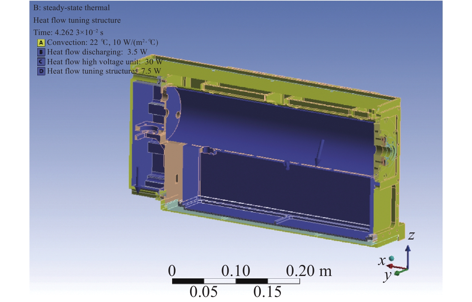
使用Ansys Workbench热静态分析模块,导入装置模型,分析了表2作为输入参数时装置的温度分布和形变量分布。其中一路激光器截面上的热源设置见图3。其他的输入参数有:外壳表面的换热系数10 W/(m2·℃),腔体合金铝导热系数155 W/(m2·℃),环境温度−20~40 ℃。

图 3 单路腔体截面上的部分内热源分布(紫)和外表面对流换热(黄)设置
Figure 3. Distribution settings of inner heat sources (purple) and exterior heat exchanging (yellow) in the section plane of single path cavity
图4(a)和图4(b)模拟了22 ℃环境温度下内部热源引起的腔体温度分布和形变分布。计算结果显示,温度分布和形变量在方位向的分布是基本对称的。在俯仰方向,温度分布和形变分布从上往下逐渐递增。图4(c)模拟的是输出镜片安装槽面各点沿着光轴方向(右下角x轴)的偏移量,结合偏移量的分布差异以及环形槽的内径,可计算出输出镜的方位和俯仰角变化。图4(d)显示了伺服电机的悬挂安装面的形变,沿右下角所示z轴方向的偏移量分布可换算为光栅的俯仰角变化,沿右下角x轴方向上的偏移量分布可换算为俯仰角变化。图4(c)和图4(d)模拟得到的谐振腔镜偏离方向与实验结果一致。
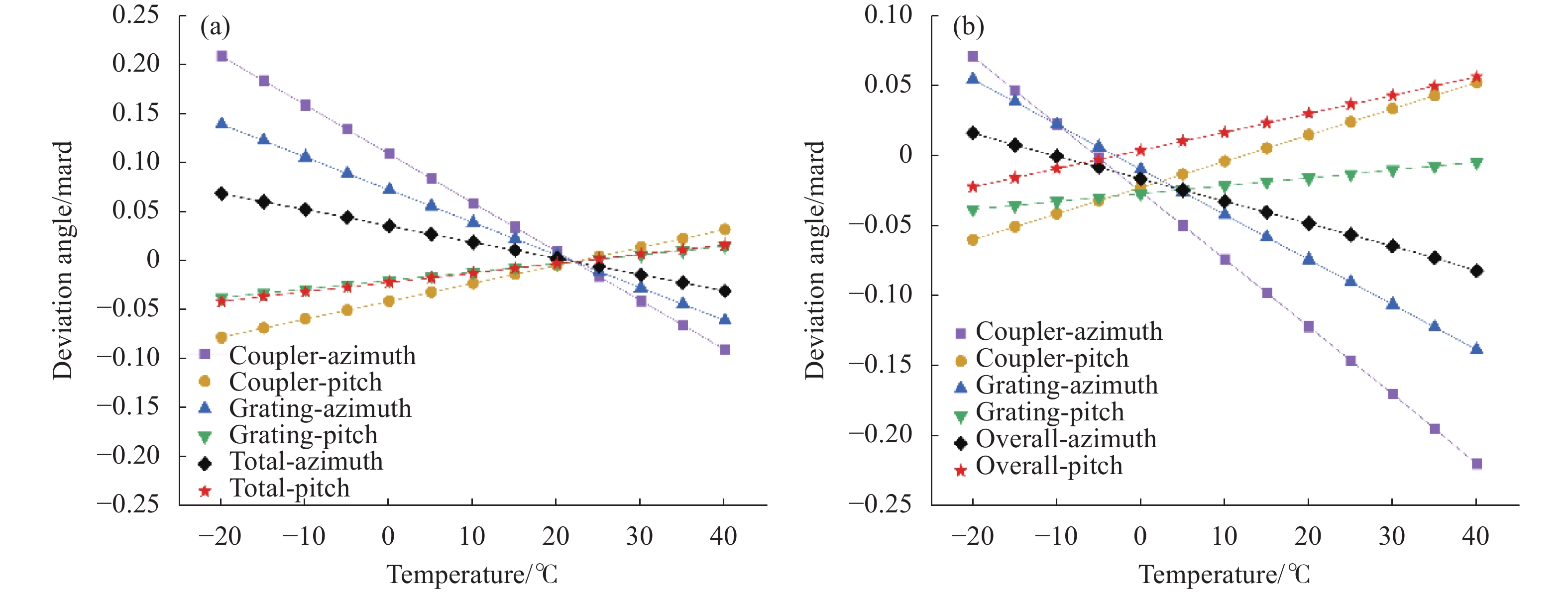
图5(a)和图5(b)分别给出了无内部内热源、存在内部热源时耦合输出镜Coupler和光栅Grating在方位维度Azimuth和俯仰维度Pitch上的变化量随环境温度的变化。将22 ℃无热源状态设为形变量参考零点。图5(a)表明,无内部热源时,前后谐振腔镜在不同维度上的偏离角数据呈线性分布且相交于参考零点。根据热形变理论,这种线性变化是由整体环境温度变化引起的整体热胀冷缩所导致。当存在多点分布热源时,在腔体上叠加了多个不同位置、不同方向、不同幅度的弹性应力形变。图5(b)对应图4的模拟数据,得到的数值和公式(14)中的实验值接近。图5(b)还显示了这种弹性形变的叠加并不改变各偏离角拟合线的斜率,而是改变其与纵坐标的截距,使各拟合线之间产生多个交点,而非图5(a)中的仅一个交点。菱形和星形数据线描绘的整体方位和俯仰角变化,由输出镜数据减去光栅数据获得,有内部封闭热源作用时,两者的交点22 ℃移动到−6 ℃附近,对应幅值略小于0。

图 4 热源全密闭条件下的 (a) 温度分布;(b) 热形变分布;(c) 耦合输出镜安装基面沿光轴方向形变分布;(d) 伺服电机安装基面沿光轴方向形变分布
Figure 4. Simulation results under the circumstance of all sealed thermal sources. (a) Total temperature distribution; (b) Total deformation distribution; (c) Deformation distribution of the mounting surface of the output coupler, along the direction of optical axis; (d) Deformation distribution of the mounting surface of the servo motor, along the direction of optical axis

图 5 谐振腔镜角度偏离计算情况。(a) 无内部热源;(b) 有内部封闭热源
Figure 5. Calculated deviation angle of cavity mirrors. (a) Without inner heat sources; (b) With all-sealed inner sources
-
为抑制内部热源引起的形变,对热功率最高的高压电源实施主动热交换,具体方案如图6所示。将下方高压电源舱室的盖板一端开出风口并安装轴流风扇,另一端设置栅格状进风口。设置了箭头所示的气流通道。其中风扇扇面直径60 mm,风扇供电28 V,最大风量60 cfm。软件计算图6中所示内部通道面积约0.12 m2,通道截面积约2300 mm2,通道长度约0.53 m。

图 6 高压电源舱室内部气流路径示意图
Figure 6. Schematic diagram of the flow path in the high voltage power supply chamber
由于腔内元器件众多,气体流动路径复杂,严格计算空气对流换热系数相对困难。文中仅通过尝试提高对流换热系数以分析主动对流换热对谐振腔稳定性的影响。因此空气强制对流换热系数取值参考了文献中的范围20~100 W/(m2·℃)[18]。仿真中对气流迎风面设置三种不同空气对流换热系数,分别是10 W/(m2·℃)(自然流动)、40 W/(m2·℃)(中等流速)、70 W/(m2·℃)(高速流动),计算了对应的谐振腔整体方位向和俯仰向的偏离角并绘于图7。
仿真结果表明,谐振腔整体在两个维度上的偏离角随环境温度始终呈线性变化。实施热交换后,两个维度偏离角拟合线的交点位置(图中红色星形标记)从−7 ℃变化为13 ℃,幅值略低于0。随着对流换热系数的提高,交点位置从13 ℃附近逐渐向22 ℃靠拢并趋向于图5(a)的情形,此时对流换热系数足以消除大多数内部热源对谐振腔的形变影响。在13~22 ℃区间范围内,可以通过调整对流换热系数,来实现环境引起的整体热胀冷缩作用以及内部热源引起的加热变形作用的抵消。
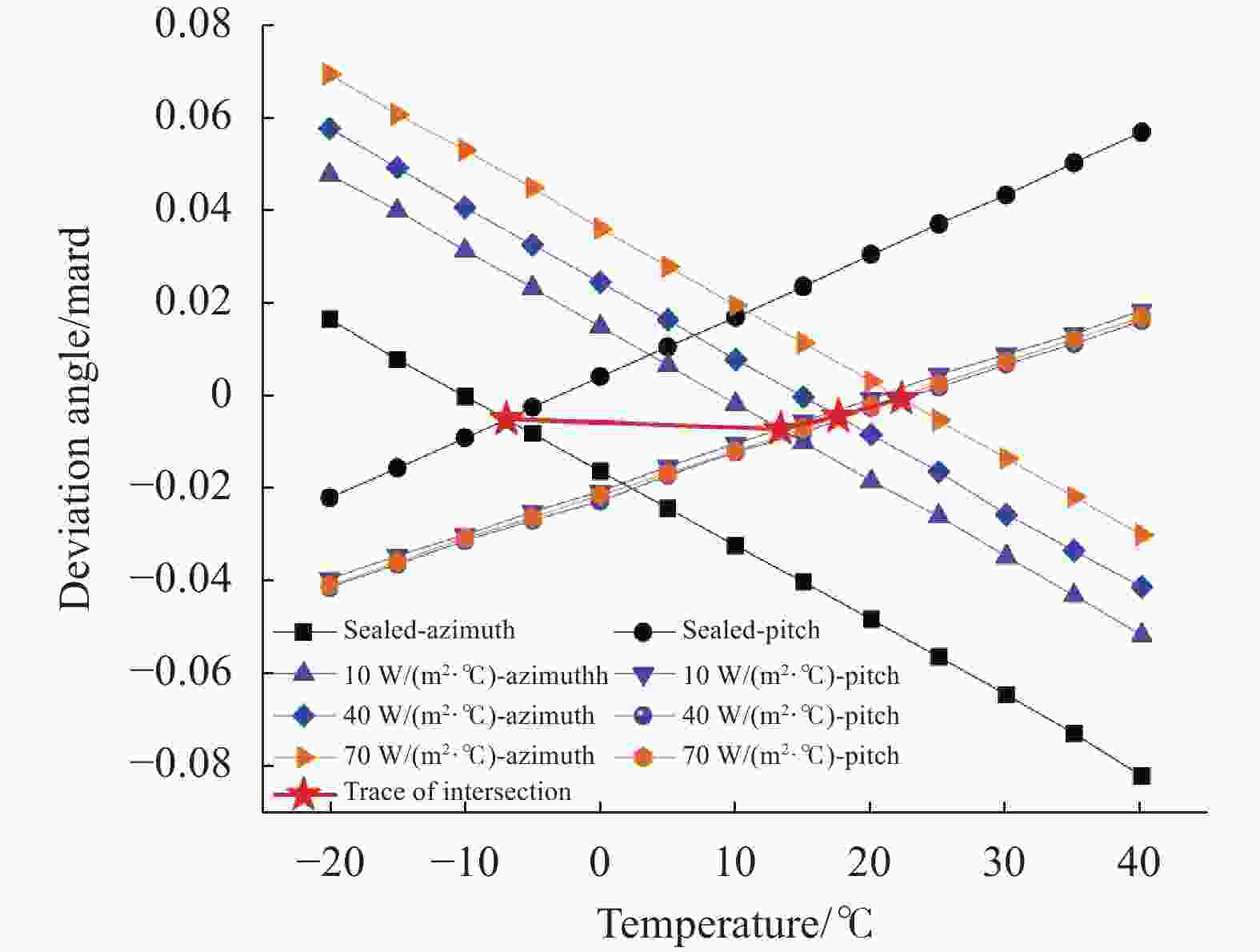
图 7 不同对流换热系数下谐振腔在方位和俯仰方向上的整体偏离角
Figure 7. Overall resonant cavity deviation angle in the azimuth and pitch direction under different transfer convection coefficients
在室温22 ℃条件下,实验测试了加入对流换热前后,激光器输出脉冲能量随时间变化的变化曲线,见图8。两条曲线在前600个脉冲阶段存在一个短暂的凹陷,这是个热传导和热平衡的过程,随后曲线逐渐保持一个较稳定的斜率开始下降。采取对流换热措施后,激光脉冲能量变化曲线的下降斜率有明显的改善,也未通过反射光点观察到前后谐振腔镜的偏移,即脉冲能量的下降与谐振腔形变因素无关。

图 8 采用风扇热交换前后1#激光器脉冲能量随时间的变化,红色4200个脉冲,蓝色7200个脉冲,工作频率1 Hz
Figure 8. Pulse energy of 1# laser under repetition 1 Hz, total 4200 pulses of sealed structure (red), 7200 pulses with DC fan adopted (blue)
-
通过调节对流换热系数实现谐振腔稳定性的方法仅适用于13~22 ℃的较小温度范围。为实现更宽温度范围的谐振腔稳定性,需有足够的对流换热系数以消除大部分内部热源的形变作用,并在此基础上对谐振腔的整体热胀冷缩形变进行两个维度方向上的角度补偿。此外总结补偿值与传感器采集到的温度数据的线性关联函数,使得控制单元能够根据实时的温度数据及时做出修正。
方位向的补偿是采用伺服电机调整光栅偏转角等于谐振腔整体的偏移角。根据图5(a)环境温度上升带来的方位方向偏移角变化的斜率:
$$ {k}_{A}\approx -\frac{0.01}{6} \;{\rm{mrad}}/\text{℃} $$ (15) 对于20位编码器的伺服电机,一圈为$ {2^{20}}= 1\;048\;576 $步(step),增加步数是逆时针/负角度,因此理论上环境温度每上升1 ℃对应电机步数补偿规律(实际取整)为:
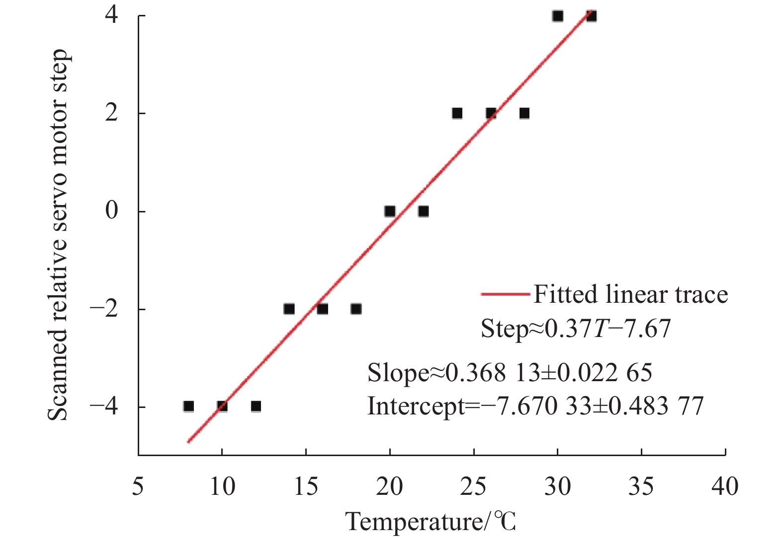
$$ {k}_{A}\approx 0.28\;\text{step}/\text{℃} $$ (16) 图9给出了实验中测得的伺服电机补偿数值,横坐标是温度,纵坐标是补偿步数。补偿步数计算方法为,根据伺服电机扫描得到的最大脉冲能量所对应的电机步数,减去原设定的(无热影响时)步数。实验测得的电机补偿值随温度的变化整体呈线性关系,且拟合线斜率比公式(16)给出的理论值偏大,这可能是因为文中假设热源对附近设备内壁的加热效果以及热交换效果是理想的均匀分布,实际测量时的局部温差和热形变可能幅度更大。
俯仰向的补偿方案是对悬挂安装的伺服电机的底部加装由PZT压电陶瓷驱动器控制位移的底座。如图10所示,当底座在沿光轴方向上的偏移量为$\Delta l$,$\Delta l$距离伺服电机的悬挂安装面的高度差h,通过角度关联可知光栅在俯仰向的偏移角为:
$$ \theta {\text{ = }}{{\Delta l} \mathord{\left/ {\vphantom {{\Delta l} h}} \right. } h} $$ (17) 根据图7,该方向的补偿角随环境温度变化的斜率应满足:
$$ {k}_{P}\approx 0.009\;8\;\text{mrad}/\text{℃} $$ (18) 根据$h \approx 81 {\rm{mm}}$换算得到每上升1 ℃对应的PZT位移为:
$$ \Delta l\approx 0.79\;\text{μm}/\text{℃} $$ (19) 
图 9 不同环境温度下扫描最大脉冲能量对应的电机步数补偿值
Figure 9. Compensation motor steps under different environmental temperatures by scanning maximum pulse energy

图 10 俯仰方向偏离角补偿示意图
Figure 10. Schematic diagram of the angular deviation compensation in the pitch direction
-
文中针对紧凑型双路TEA CO2激光器谐振腔的热稳定性开展了研究,分别用实验和仿真的方法,分析了内部热源对谐振腔稳定性的影响,提出并验证了热交换和角度补偿的方案。主要结论包括:
1)谐振腔镜在方位和俯仰维度上的指向性随环境温度呈线性变化,变化的斜率仅和腔体的整体热胀冷缩特性有关,与内部热源的影响无关。两个维度的指向性变化拟合线存在一个交点,当无内部热源时,交点对应设定的谐振腔初始光轴的环境温度22℃,交点处幅值为零。当存在内部热源时,交点对应的环境温度会向低温方向移动,幅值为接近零的负值。
2)加入热交换时,改变对流换热系数,可使内部热源的局部加热效应和腔体的整体热胀冷缩达到基本平衡,从而调节上述交点位置,使13~22 ℃的环境温度范围内谐振腔指向性变化降到接近零的水平。
3)为实现更宽温度范围内谐振腔的稳定性,在利用热交换消除绝大部分内部热源影响的基础上,采用角度补偿方法应对腔体整体的热胀冷缩变形。其中方位向的补偿是通过改变伺服电机步数来实现光栅工作角度的微调。俯仰角的补偿则是通过PZT压电陶瓷促动器调节悬臂结构端部位移实现对伺服电机俯仰角的控制。
文中的研究内容和方法为双路紧凑型TEA CO2激光器及同类小型激光器件、尤其是气体激光器谐振腔热稳定性的研究,提供了对局部加热效应的新认识,以及对相关问题的解决方法。后续的工作将通过对装置的结构优化,以及尝试结合采用负热膨胀材料等,进一步减小谐振腔的热形变,提高谐振腔热稳定性。
Thermal stability and compensation of compact dual-path TEA CO2 laser resonant cavities
-
摘要: 通过实验和仿真的方法,研究了多点分布的内部热源加热作用对紧凑型双路TEA CO2激光器谐振腔热稳定性的影响。采用直流风扇热交换抑制了高压电源的局部加热效应,通过调整热交换的效率,可在13~22 ℃环境温度范围内,使前后谐振腔镜受到的局部加热形变作用和环境温度引起的热胀冷缩作用基本抵消。为实现更宽温度范围的谐振腔稳定性,在有效热交换措施的基础上,根据模拟预测的形变规律,提出了谐振腔变形的角度补偿方法。使用传感器获得环境温度与设定初始环境温度的偏差,通过调整伺服电机步数实现对方位角的补偿,补偿值约0.28 step/℃,通过PZT促动器调整悬臂调谐结构末端位移,实现对俯仰角的补偿,补偿值约0.79 μm/℃。
-
关键词:
- TEA CO2 激光器 /
- 局部加热效应 /
- 腔体形变 /
- 角度补偿
Abstract:Objective Transversely Excited Atmospheric (TEA) CO2 laser can achieve tunable output at 9-11 μm which covers several atmospheric windows. It has improved a lot towards higher peak power and repetition frequency in the applications such as laser radar and laser manufacturing since the beginning of the 21st century. Heat effect as a product of gas discharging may bring unwelcomed effects on laser components and parts. Previous researches mainly focused on thermal deformation of laser windows under the situation of multi-kilowatt output. With the finite element theory, specific deformation data features were studied and corresponding compensation methods were proposed as well. However, thermal deformation of laser resonant cavities was commonly neglected as the huge bulk of cavities had large thermal capacity and good heat dissipation. With the recent development of lidar applications, opposite demand of TEA CO2 lasers for small size and high reliability was put forward. Consequently, thermal deformation of resonant cavity instead of laser window is more likely to take place due to local heat effect. By far rare research works were carried out on this topic. For this purpose, thermal stability and compensation of compact dual-path TEA CO2 laser resonant cavities were studied. Methods A compact dual-path TEA CO2 laser was developed. Deformation of resonant cavity in the action of local heat effect was measured with an indication beam (Fig.2, Eq.(14)). It was also simulated in both azimuth and pitch directions with Ansys Workbench (Fig.4-5). Hypothesis of the deformation counteract by balancing the local heat effect with thermal expansion was calculated (Fig.7) and experimentally realized by an axial flow DC fan assisted heat extraction structure (Fig.6, Fig.8). Moreover, angular compensation measures were taken after restraining the local heat effect. The azimuth angular compensation was achieved by adjusting servo motor steps under different ambient temperatures. The pitch angular compensation was realized by changing the bottom displacement of the cantilever tuning structure with a PZT actuator. Results and Discussions The angular deviation of resonant cavity mirrors changed linearly regardless the presence of local heat effect. While local heat effect caused unequal angular deviation between resonant cavity mirrors. By adjusting heat exchanging efficiency, local heat and overall heat expansion reached a balanced counteraction in cavity deformation, thus the deviation of resonant cavities mirrors was limited to a low level within 13-22 ℃. Output pulse energies decreased more gently in the condition of enhanced heat exchange. Angular compensation slopes were confirmed to realize the stability of resonant cavities within a wider temperature range, they were 0.28 step/℃ for servo motor in the azimuth direction and 0.79 μm/℃ for PZT actuator in the pitch direction respectively. Conclusions Thermal stability and compensation of compact dual-path TEA CO2 laser resonant cavities was studied. The heat effect of distributed inner heat sources was studied both in experimental and simulated method. Active heat exchange plan by adopting an axial flow DC fan was adopted to constrain the local heat effect. Hypothesis of the deformation counteract between local heat effect and thermal expansion was proposed and demonstrated. Moreover, the adaptability in wider temperature range was realized by precise angular compensation. Investigation results provided comprehensive view about thermal deformation in compact volume and angular compensation idea would be a reference for similar laser devices. -
Key words:
- TEA CO2 laser /
- local heat effect /
- cavity deformation /
- angular compensation
-
图 2 谐振腔俯仰角失谐引起的光斑形状变化。(a)初始状态;(b)失谐状态
Figure 2. Spot shape variation caused by angle of pitch detuning in resonant cavity. (a) Original status; (b) Detuning status
图 3 单路腔体截面上的部分内热源分布(紫)和外表面对流换热(黄)设置
Figure 3. Distribution settings of inner heat sources (purple) and exterior heat exchanging (yellow) in the section plane of single path cavity
图 4 热源全密闭条件下的 (a) 温度分布;(b) 热形变分布;(c) 耦合输出镜安装基面沿光轴方向形变分布;(d) 伺服电机安装基面沿光轴方向形变分布
Figure 4. Simulation results under the circumstance of all sealed thermal sources. (a) Total temperature distribution; (b) Total deformation distribution; (c) Deformation distribution of the mounting surface of the output coupler, along the direction of optical axis; (d) Deformation distribution of the mounting surface of the servo motor, along the direction of optical axis
图 5 谐振腔镜角度偏离计算情况。(a) 无内部热源;(b) 有内部封闭热源
Figure 5. Calculated deviation angle of cavity mirrors. (a) Without inner heat sources; (b) With all-sealed inner sources
图 6 高压电源舱室内部气流路径示意图
Figure 6. Schematic diagram of the flow path in the high voltage power supply chamber
图 7 不同对流换热系数下谐振腔在方位和俯仰方向上的整体偏离角
Figure 7. Overall resonant cavity deviation angle in the azimuth and pitch direction under different transfer convection coefficients
图 8 采用风扇热交换前后1#激光器脉冲能量随时间的变化,红色4200个脉冲,蓝色7200个脉冲,工作频率1 Hz
Figure 8. Pulse energy of 1# laser under repetition 1 Hz, total 4200 pulses of sealed structure (red), 7200 pulses with DC fan adopted (blue)
图 9 不同环境温度下扫描最大脉冲能量对应的电机步数补偿值
Figure 9. Compensation motor steps under different environmental temperatures by scanning maximum pulse energy
图 10 俯仰方向偏离角补偿示意图
Figure 10. Schematic diagram of the angular deviation compensation in the pitch direction
表 1 双通道激光的主要输出参数
Table 1. Main parameters of dual path
Parameter Numerical value Pulse energy for strong line/mJ >50 Pulse energy for weak line/mJ >10 Pulse width (full width at half maximum)/ns 60-150 Repetition rate/Hz 1 Minimum aperture (near grating)/mm 8 Beam divergence/mrad <4 Transverse mode TEM00 & TEM01 Number of output lines 70  下载: 导出CSV
表 2 热源参数(单位:W)
Table 2. Parameters of heat sources (Unit: W)
Parameter Numerical value Gas discharging (each path) 3.5 Servo motor (each path) 7.5 High voltage power supply (each path) 30 Control unit (common) 5
下载: 导出CSV
-
[1] Menyuk N, Moulton P F. Development of a high-repetition-rate mini-TEA CO2 laser [J]. Review of Scientific Instruments, 1980, 51(2): 216-220. doi: 10.1063/1.1136176 [2] Menyuk N, Killinger D K, Defeo W E. Laser remote sensing of hydrazine, MMH, and UDMH using a differential-absorption CO2 lidar [J]. Applied Optics, 1982, 21(12): 2275-2286. [3] Kariminezhad H, Parvin P, Borna F, et al. SF6 leak detection of high-voltage installations using TEA CO2 laser-based DIAL [J]. Optics and Lasers in Engineering, 2010, 48(4): 491-499. doi: 10.1016/j.optlaseng.2009.08.011 [4] Yang Z, Zhang Y, Chen Y, et al. Simultaneous detection of multiple gaseous pollutants using multi-wavelength differential absorption LIDAR [J]. Optics Communications, 2022, 518(1): 128359. [5] Qu Y, Ren D, Zhang L, et al. A rapidly tunable TEA CO2 laser for differential absorption lidar[C]//Proceedings of SPIE, 2005, 5627: 537-543. [6] 郑义军, 朱子任, 谭荣清, 等. 双光路快速调谐脉冲CO2激光器[J]. 红外与激光工程, 2020, 49(1): 6. Zheng Yijun, Zhu Ziren, Tan Rongqing, et al. Rapidly tuned pulsed CO2 laser with dual optical path [J]. Infrared and Laser Engineering, 2020, 49(1): 0105001. (in Chinese) [7] 潘其坤, 苗昉晨, 司红利, 等. 紧凑型波长自动调谐脉冲CO2激光器[J]. 中国光学, 2022, 15(5): 1007-1012. Pan Qikun, Miao Fangchen, Si Hongli, et al. Compact pulsed CO2 laser with wavelength automatic tuning [J]. Chinese Optics, 2022, 15(5): 1007-1012. (in Chinese) [8] 陈佳元. 高功率TEA CO2激光器腔镜热稳定性研究 [D]. 武汉: 华中科技大学, 2009. Cheng Jiayuan. Study on the stability of mirrors of high power TEA CO2 laser [D]. Wuhan: Huazhong University of Science & Technology, 2009. (in Chinese) [9] 何建国, 李明, 貊泽强, 等. 高功率板条激光介质的纵向强制对流换热技术[J]. 红外与激光工程, 2020.49(9): 20200556. doi: 10.3788/IRLA20200556 He Jianguo, Li Ming, Mo Zeqiang, et al. Longitudinal forced convection heat transfer for high power slab laser media [J]. Infrared and Laser Engineering, 2020, 49(9): 20200556. (in Chinese) doi: 10.3788/IRLA20200556 [10] 张阔, 陈飞, 李若斓, 等. 大功率CO2激光器输出窗口热性能分析[J]. 红外与激光工程, 2017, 46(2): 6. doi: 10.3788/IRLA201645.0205005 Zhang Kuo, Chen Fei, Li Ruolan, et al. Analysis on thermal performance of output window in high power CO2 laser [J]. Infrared and Laser Engineering, 2017, 46(2): 0205005. (in Chinese) doi: 10.3788/IRLA201645.0205005 [11] 王庆雷, 孙世君, 姜宏佳, 等. 光学遥感器光机结构热变形的高精度测量[J]. 光学精密工程, 2022, 30(8): 948-959. doi: 10.37188/OPE.20223008.0948 Wang Qinglei, Sun Shijun, Jiang Hongjia, et al. High-precision thermal deformation measurement of optical remote sensor optical-mechanical structure [J]. Optics and Precision Engineering, 2022, 30(8): 948-959. (in Chinese) doi: 10.37188/OPE.20223008.0948 [12] 冯志庆, 白兰, 张增宝, 等. 高能激光反射镜热变形补偿[J]. 光学精密工程, 2010, 18(008): 1781-1787. Feng Zhiqing, Bai Lan, Zhang Zengbao, et al. Thermal deformation compensation of high energy laser mirrors [J]. Optics and Precision Engineering, 2010, 18(8): 1781-1787. (in Chinese) [13] 王文进. 高功率轴快流CO2激光器气体强化传热研究 [D]. 武汉: 华中科技大学, 2015. Wang Wenjin. Research on gas heat transfer enhancement in high power fast axial flow CO2 laser [D]. Wuhan: Huazhong University of Science & Technology, 2015. (in Chinese) [14] 赵紫云, 张阔, 周峰, 等. 机载宽温域工作CO2激光器温控方法[J]. 中国光学, 2022, CO. 2022-0089. Zhao Ziyun, Zhang Kuo, Zhou Feng, et al. Temperature control method of CO2 laser operating in airborne wide temperature range [J]. Chinese Optics, 2022, 16(2): 390-398. (in Chinese) [15] 曾元, 谭荣清, 陈静. 可调谐TEA CO2激光器谐振腔结构稳定性研究[J]. 激光与红外, 2009, 39(9): 3. Zeng Yuan, Tan Rongqing, Chen Jing. Research on stability of tunable TEA CO2 laser resonator [J]. Laser & Infrared, 2009, 39(9): 928-930. (in Chinese) [16] 樊越. 航空相机光机热分析与热控技术研究 [D]. 成都: 中国科学院大学, 2013. Fan Yue. Thermal/structural/optical analysis and thermal control technique of aerial camera [D]. Chengdu: University of Chinese Academy of Sciences, 2013. (in Chinese) [17] Ray S, Shamanna J. On virtual displacement and virtual work in Lagrangian dynamics [J]. European Journal of Physics, 2006, 27(2): 311-329. [18] 张国连. 大功率电源柜风冷散热系统研究 [D]. 西安: 长安大学, 2021. Zhang Guolian. Research on air cooling system of high power supply cabinet [D]. Xi'an: Chang’an University, 2021. (in Chinese) -

 点击查看大图
计量
- 文章访问数: 116
- HTML全文浏览量: 23
- PDF下载量: 45
- 被引次数: 0

