


 下载:
下载:


-
激光陀螺的工作原理是Sagnac效应[1],它能够将相对于惯性空间的角运动转换为拍频输出,激光陀螺广泛应用于导航、定位定向及精密测角仪等领域[2-6]。由于镜片的背向散射和环路的非均匀性,激光陀螺存在“闭锁”现象[7-14],即当输入转速低于某一阈值时,陀螺中的正逆行光之间产生同步现象,不再感知外部角运动。为了减小锁区的影响,必须对激光陀螺进行偏频,其中机械抖动偏频是目前精度最高的偏频方式,应用也最为广泛[15-17]。
机抖偏频陀螺的缺点是一个周期需要两次经过锁区,每次过锁区会产生一定的信息丢失,抖动噪声注入能够将过锁时的信息丢失随机化,但不能消除这一误差,这就会在陀螺的输出信号中产生随机游走误差。锁区补偿能够得到过锁区的误差并进一步对这一误差进行补偿。
文献[18]在总结了锁区补偿相关研究的基础上,得到了过锁误差的表示方法,并对锁区补偿的效果进行了数值仿真,仿真结果表明锁区补偿在各种转速条件下是可行的。在文献[18]的基础上,通过合理的工程设计,实现了激光陀螺的锁区补偿。文献[18]中的数值仿真中假设了锁区和偏移角是已知的,但在实际情况下这两个参数是未知的,采用了曲线拟合的方法得到了它们的值。首次实现了机抖陀螺的过锁误差补偿,并用Allan方差方法分析了锁区补偿的效果。实验结果表明:某陀螺的角度随机游走由$1.53 \times {10^{ - 3 }}{(^ \circ)} /\sqrt {\rm{h}} $ 改善到了 $3.14 \times {10^{ - 4}}{(^\circ)} /\sqrt {\rm{h}} $,锁区补偿达到了预期的效果。
-
二频激光陀螺的拍频方程表示为:
$$ \dot \psi = \varOmega + {\varOmega _L}\cos \left( \psi \right) $$ (1) 式中:$ \psi $为激光陀螺拍频信号的瞬时相位;$ {\varOmega _L} $为激光陀螺的锁区;$ \varOmega $为外界输入角速率。抖动偏频下的拍频方程表示为:
$$ \dot \psi = \varOmega + {\varOmega _d}\cos \left( {{\omega _d}t} \right) + {\varOmega _L}\cos (\psi ) $$ (2) 式中:$ {\varOmega _d} $为抖动的峰值速率;$ {\omega _d} $为抖动频率。机抖陀螺中锁区引起的误差主要集中在过锁瞬间。过锁区的误差表示为[18]:
$$ \begin{gathered} \Delta {E^ + } = {\varOmega _L}\sqrt {\frac{{2\pi }}{{{{\ddot \psi }^ + }}}} \cos \left(\psi _0^ + - \frac{\pi }{4}\right) \\ \Delta {E^ - } = {\varOmega _L}\sqrt {\frac{{2\pi }}{{{{\ddot \psi }^ - }}}} \cos \left(\psi _0^ - + \frac{\pi }{4}\right) \\ \end{gathered} $$ (3) 式中:$ \Delta {E^ + } $和$ \Delta {E^ - } $分别表示正向过锁区和负向过锁区的误差;$ \psi _0^ + $和$ \psi _0^ - $分别为正负向过锁区时零速率点的相位;$ \ddot \psi $为过锁区的相位加速度。每个周期的过锁误差表示为[18]:
$$ \Delta {E_c} = a{P_1} + b{P_2} $$ (4) 式中:$ a $和$ b $为和锁区与偏移角相关的常量。$ {P_1} $和$ {P_2} $的表达式为[18]:
$$ \begin{gathered} {P_1} = \sqrt {\frac{{2\pi }}{{{{\ddot \psi }^ + }}}} \sin (\psi _{H1}^ + ) + \sqrt {\frac{{2\pi }}{{{{\ddot \psi }^ - }}}} \sin (\psi _{_{H2}}^ - ) \\ {P_2} = \sqrt {\frac{{2\pi }}{{{{\ddot \psi }^ + }}}} \sin (\psi _{_{H2}}^ + ) - \sqrt {\frac{{2\pi }}{{{{\ddot \psi }^ - }}}} \sin (\psi _{_{H1}}^ - ) \\ \end{gathered} $$ (5) 式中:$ \psi _{_{H1}}^{} $和$ \psi _{_{H2}}^{} $分别为两个读出光电管的瞬时相位。通过和光棱镜可以将顺逆时针光在干涉面上形成干涉条纹,两个光电管在干涉面上互成正交放置。
-
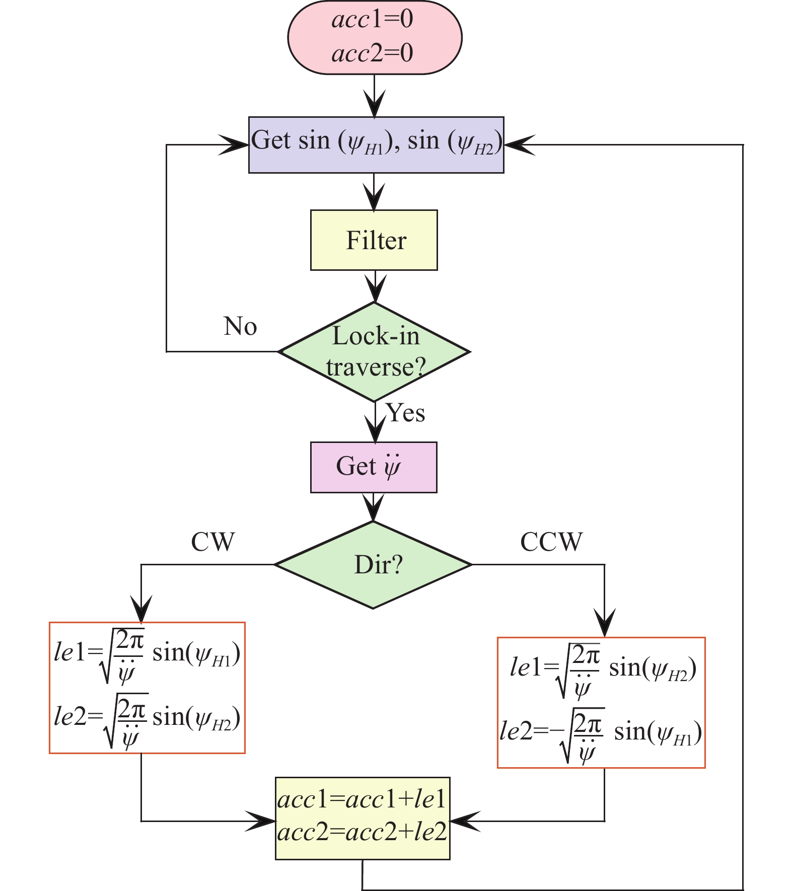
获取过锁区误差的流程图如图1所示。首先通过高速ADC获取读出光电管的瞬时的拍频信号$ \sin ({\psi _{H1}}) $和$ \sin ({\psi _{H2}}) $。对这两个信号进行滤波处理,就可以判断陀螺是否过锁区[19]。如果陀螺过锁区,就按照公式(5)计算过锁误差信息,并将过锁误差信息累积到acc1和acc2,它们即是$ {P_1} $和$ {P_2} $在所有抖动周期内的累积。
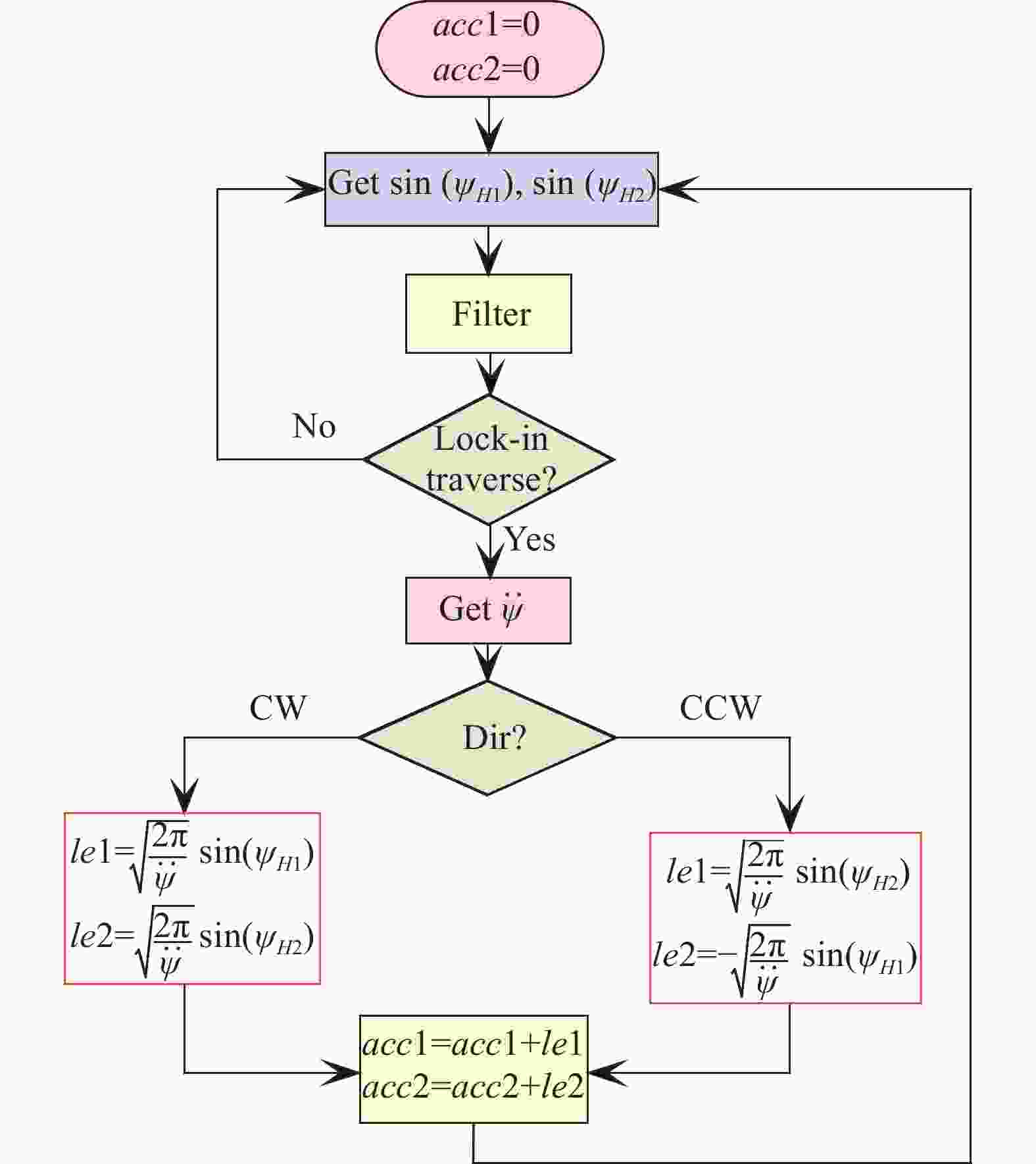
图 1 获取过锁误差的流程图
Figure 1. Flow chart of obtaining over-lock error
对激光陀螺的读出信号进行正交解调,通过可逆计数器就可以得到陀螺的输出脉冲数。由于机抖陀螺中含有抖动偏频成分,要得到真实的外界角速度输入,必须对可逆计数器进行采样,并采用低通滤波器将抖动成分滤除[20]。低通滤波器必然会引入时间延迟,会造成脉冲输出和上述采集到的误差信息的不同步。为了解决这个问题,将误差累积信号也同样经历了输出脉冲的采样、低通滤波等处理流程,以使得输出脉冲和误差累积量是同步的。
经过上述同步滤波处理,可以得到每一秒钟之内的脉冲输出序列X,还可以得到acc1和acc2每一秒钟的累积序列Y和Z,根据公式(4)可以得到经过补偿之后的输出序列为:
$$ {{G}} = {{ X }} - {{aY}} - {{bZ}} $$ (6) 公式(6)即为锁区补偿的表达式,然而$ a $和$ b $的值是未知的。但是$ a $和$ b $可以通过公式(7)来估计[21]:
$$ \left( {\begin{array}{*{20}{c}} a \\ b \end{array}} \right) = C{(Y,Z)^{ - 1}}\left( {\begin{array}{*{20}{c}} {{cov} (X,Y)} \\ {{cov} (X,Z)} \end{array}} \right) $$ (7) 式中:$ {cov} \left( {X,Y} \right) $为$ X $和$ Y $的协方差。$ C(Y,Z) $的表达式为:
$$ C(Y,Z) = \left( {\begin{array}{*{20}{c}} {{cov} (Y,Y)}&{{cov} (Y,Z)} \\ {{cov} (Y,Z)}&{{cov} (Z,Z)} \end{array}} \right) $$ (8) 为了使得$ a $和$ b $的估计具有足够的精度,数据采集时间一般需要10 min~1 h。
-
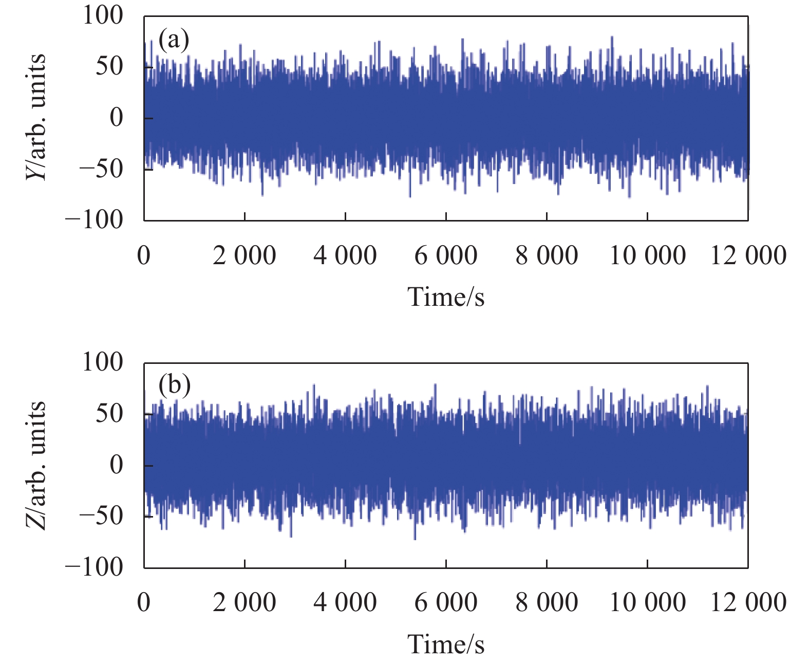
在以上锁区补偿工程实现的基础上开展锁区补偿实验,被测陀螺的光学程长为0.28 m,陀螺的抖频为359 Hz,和频值为150 kHz。将激光陀螺水平放置,以地球自转为被测量,将抖动噪声加至正常水平以使得过锁区的误差充分随机化。通过数据采集得到激光陀螺的输出如图2所示,从图中可以看到由于陀螺过锁区时引起的误差,陀螺的输出具有较大的波动。在得到激光陀螺输出的同时还能够得到激光陀螺的误差序列$Y$和$Z$如图3所示,由于加噪较为充分,可以看出误差序列$Y$和$Z$是接近白噪声的。

图 2 未进行锁区补偿前的激光陀螺输出
Figure 2. Laser gyro output before lock compensation

图 3 误差序列Y和Z
Figure 3. Error sequence Y and Z
公式(7)可得到$ a $和$ b $的值,再根据公式(6)进行锁区补偿,可以得到补偿后的激光陀螺输出如图4所示。也可以得到陀螺的锁区为$109{(^\circ)} /{\rm{h}}$。对比图4和图2可知,补偿后的激光陀螺输出比补偿前的波动小了很多。

图 4 锁区补偿后的激光陀螺输出
Figure 4. Laser gyro output after lock compensation
为了分析锁区补偿的效果,分别求图2和图4中的数据进行Allan方差,得到的结果如图5所示,可以看到,补偿后数据的Allan方差比补偿前数据的Allan方差下移很多。分别对两条曲线进行数据拟合,可以得到锁区补偿前的随机游走为$1.53 \times {10^{ - 3}}{(^\circ)} /\sqrt {\rm{h}} $,锁区补偿后的随机游走为$3.14 \times {10^{ - 4}}{(^\circ)} /\sqrt {\rm{h}} $,仅为补偿前的1/5,可见锁区补偿确实能够降低二频机抖陀螺的随机游走。

图 5 补偿前后的Allan方差曲线
Figure 5. Allan variance curve before and after compensation
-
机抖陀螺每次过锁区的随机误差会使输出产生角度随机游走误差,在频域上,角度随机游走误差可延伸至有用信号频带范围内,很难通过滤波的方法滤除,因此随机游走决定了导航系统的极限精度。若过锁误差能够得到补偿,便可进一步降低激光陀螺的随机游走。在文献[18]理论分析的基础上,首次在工程上实现了机抖陀螺的锁区补偿。采用Allan方差方法对锁区补偿的效果进行了分析,对某陀螺实验结果表明锁区补偿后的角度随机游走降低为原来的1/5。需要注意的是锁区补偿的适用范围是输入角速率不能超过偏频量,当输入转速过大时,陀螺不经过锁区,也就不存在过锁区误差。
Angle random walk improvement analysis of body-dithered ring laser gyro based on lock-in error compensation
-
摘要: 二频机抖陀螺每个抖动周期要两次经过锁区,每次过锁区时的随机误差会使激光陀螺产生随机游走。在工程上实现了二频机抖陀螺的锁区补偿,并采用Allan方差方法分析了锁区补偿前后输出数据的角度随机游走,实验结果表明,锁区补偿后随机游走具有大幅度的改善。首次报道了机抖激光陀螺中锁区补偿对角度随机游走的改善。Abstract:
Objective Ring laser gyro is widely used in navigation, positioning, precision goniometer and other fields. Due to the backscattering of the reflectors and the non-uniformity of the optical loop, ring laser gyro has the lock-in phenomenon. In order to reduce the influence of the locking zone, the laser gyro must be biased. Mechanical dither bias is the method with the highest accuracy and is most widely used. However, mechanical dither bias has the defect that it needs to pass through the locking region twice in one cycle, and certain rotation signal loss will be generated each time it passes through the locking region. Jitter noise injection can randomize the rotation signal loss during the locking process, but it cannot eliminate this error, which will generate random walk error in the output of the gyroscope. In order to eliminate the lock-in error, the lock compensation is carried out. Methods The lock compensation can obtain the error through the locking area and further compensate the error. In this paper, the lock compensation of laser gyro is realized for the first time through reasonable engineering design. The two instantaneous beat signals of the photocell are obtained by a high-speed ADC. After filtering the two signals, it can be judged whether the gyroscope has passed the locking area. If so, we can process it through the process in Fig.1. By orthogonal demodulation of read signal of laser gyro, the output pulse number of gyro can be obtained by reversible counter. Through the compensation expression, the compensation expression of the locking area is obtained. Results and Discussions The gyro output signal without locking region compensation is shown (Fig.2), and the gyro output signal with locking region compensation according to the formula is shown (Fig.4). The comparison between the two figures shows that the output fluctuation of laser gyro after compensation is much smaller than that before compensation. The data in Fig.2 and Fig.4 were analyzed respectively by Allan variance, and the results were shown (Fig.5). It can be seen that the Allan variance of the data after compensation moved down much more than that before compensation. According to the data fitting of the two curves, the random walk before the lock compensation can be calculated as $1.53 \mathrm{e}{\text{-}}3\left(^{\circ}\right)\sqrt {\rm{h}} $, and the random walk after the lock compensation is $3.14{\rm{e}}{\text{-}} 4 \left(^{\circ}\right)/ \sqrt {\rm{h}} $, which is only 1/5 of the one before the compensation. It is confirmed that the lock compensation can reduce the random walk of the gyro indeed. Conclusions The random error of each lock-in crossing in the ring laser gyro can generate the angle random walk (ARW) error in the output. In the frequency domain, the ARW error can be extended to the frequency band of useful signals, which is difficult to be filtered out by filtering method. Therefore, the random walk determines the ultimate accuracy of the navigation system. By recording the lock-in error of every lock crossing, the ARW of laser gyro is reduced. The Allan variance method is used to analyze the effect of lock compensation. The experimental results of a gyroscope show that the ARW after lock compensation is reduced to 1/5 of the original value. This is the first report of lock-in error compensation in engineering. -
Key words:
- ring laser gyro /
- beat note equation /
- lock-in error compensation /
- random walk
-
[1] Post E J. Sagnac effect [J]. Review of Modern Physics, 1967, 39(2): 475-493. doi: 10.1103/RevModPhys.39.475 [2] 龙兴武, 于旭东, 张鹏飞等. 激光陀螺单轴旋转惯性导航系统[J]. 中国惯性技术学报, 2010, 18(2): 149-153. doi: 10.13695/j.cnki.12-1222/o3.2010.02.013 Long Xingwu, Yu Xudong, Zhang Pengfei. Single-rotating inertial navigation system with ring laser gyroscope [J]. Journal of Chinese Inertial Technology, 2010, 18(2): 149-153. (in Chinese) doi: 10.13695/j.cnki.12-1222/o3.2010.02.013 [3] Majure R G. Demonstration of a ring laser gyro system for pointing and stabilization applications[C]//IEEE PLANS'90, 1990: 219-225. [4] Curran G L, Engelken D J. Ring laser gyro applications for tactical missiles: the army tacms solution[C]//Position Location and Navigation Symposium, 1990: 543-548. [5] Hadfield M J, Stiles T, Seidel D, et al. Improved ring laser gyro navigator[C]//Sensors and Sensor System for Guidance and Navigation, 1991: 126-144. [6] White D G, Psota F. A Precision navigation system for autonomous undersea vehicles[C]//Autonomous Underwater Vehicle Technology, 1996: 262-267. [7] 高伯龙, 李树棠. 激光陀螺[M]. 长沙: 国防科技大学出版社, 1980. [8] 高伯龙. 抖动偏频过锁区的理论分析[J]. 工学学报, 1979(1): 47-64. [9] Chow W W. The ring laser gyro [J]. Reviews of Modern Physics, 1985, 57(1): 61-104. doi: 10.1103/RevModPhys.57.61 [10] Faucheux M, Fayoux D, Roland J J. The ring laser gyro [J]. Journal of Optics, 1988, 19(3): 101-115. doi: 10.1088/0150-536X/19/3/001 [11] Aronowitz F. Mode coupling due to backscattering in a He-Ne traveling-wave ring laser [J]. Applied Physics Letters, 1966, 9(1): 55-58. doi: 10.1063/1.1754599 [12] Christian W R, Mandel L. Frequency depence of a ring laser with backscattering [J]. Physical Review A, 1986, 34(5): 3932-3939. doi: 10.1103/PhysRevA.34.3932 [13] Spreeuw R J C, Centeno R, Van Druten N J. Mode coupling in a He-Ne ring laser with backscattering [J]. Physical Review A, 1990, 42(7): 4315-4324. doi: 10.1103/PhysRevA.42.4315 [14] Aronowitz F. Loss lock-in in the ring laser [J]. Journal of Applied Physics, 1970, 41(6): 2453-2456. doi: 10.1063/1.1659243 [15] Killpatrick J E. Random bias for laser angular rate sensor: USA, 3467472[P]. 1969-09-16. [16] 汤建勋. 机械抖动激光陀螺抖动偏频系统的研究与设计[D]. 长沙: 国防科学技术大学, 2000. [17] Wirt T M. Dither suspension for ring laser gyroscope and method: USA, 4779985[P].1988-10-25. [18] Fan Zhenfang, Luo Hui, Lu Guangfeng. Theoretical research on lock-in error compensation for Mechanical Dithered Ring Laser Gyro [J]. Acta Optica Sinica, 2011, 31(11): 1112006. (in Chinese) [19] Fan Zhenfang, Luo Hui, Lu Guangfeng. A new noise injection effectiveness evaluation method for ring laser gyro [J]. Chinese Journal of Lasers, 2012, 39(2): 0202006. (in Chinese) [20] 樊振方. 二频机抖陀螺自动化测试系统的研制[D]. 长沙: 国防科技大学光电学院, 2008. [21] Fan Z, Luo H, Hu S, et al. Research on lock-in correction for mechanical dithered ring laser gyro [J]. Optical Engineering, 2011, 50(3): 34403. doi: 10.1117/1.3554393 -

 点击查看大图
图(5)
计量
- 文章访问数: 110
- HTML全文浏览量: 28
- PDF下载量: 20
- 被引次数: 0

