


-
随着红外成像探测系统的快速发展,如何快速而准确地评估系统的性能参数也就变得更加重要[1]。以红外动态目标模拟器为核心,构建半实物仿真系统,可以模拟真实可控的外部环境[2],在实验室中对红外系统进行测试,可以降低测试周期和成本[3],提高模拟器的性能就可以提高测试结果的稳定性和准确性[4]。
红外动态场景模拟技术的发展很多样化,常见的方法有红外阴极射线管[5]、激光二极管阵列[6]、液晶光阀[7]、硅基液晶[8]等。国外在红外成像技术上进行了大量的研究,目前国内主要采用基于DMD(数字微镜元件)器件和基于MOS电阻阵[9-10]的红外成像技术。基于DMD的红外目标模拟器的核心器件被国外所垄断,目前国内只有将可见光DMD芯片的可见窗口更换为红外窗口这一复杂的方法,才可以使其应用在红外波段,且DMD的像元尺寸与长波红外波段($8 \sim 12\;{\text{μm}}$)相近,会产生较强的衍射现象,生成的图像的对比度无法满足模拟要求,同时DMD加工工艺十分复杂,这也阻碍了它的进一步发展[11-14]。国外目标模拟器的主流技术是电阻阵列技术,国内的研究受限于复杂的控制电路,目前最大阵列规模为512×512,分辨率低,也无法满足红外成像系统的目标模拟需求。
基于红外动态场景模拟器的发展,文中设计并制备了微辐射阵列芯片,芯片通过吸收基于DMD的可见光投影技术所投影的可见光能量,转化为热能进而辐射红外光,从而实现红外动态场景模拟,弥补了DMD器件在长波红外对比度低和电阻阵列器件电路控制复杂的缺点。通过对芯片的仿真和模拟器样机的构建,验证了基于微辐射阵列的红外场景模拟技术的可行性。
-
微辐射阵列芯片作为关键转换器件,采用高吸收率/辐射率的黑体材料在平面上进行像元阵列的排布,并且黑体像元间具有足够的绝热性能,避免了像元间的温度串扰,同时每个像元还具有较小的热质量,从而使其高低温切换具有较快的速度,使所投影的红外图像有较大的帧频。
为使微辐射阵列具有较为理想的热环境,避免空气对流对器件均匀性的影响,器件整体采用真空封装。因此,对于单个微辐射元,其所处环境的热交换方式为热传导和辐射,根据两种能量的交换方式,可计算得到单个微辐射元的能量交换状态。微辐射元与基底之间可由导热层通过热传导传导热量,在真空封装条件下,可利用一维传热模型,对热传导功率进行计算。
一维传热方程如下式 [15]所示:
$$ {q}{{{'}}{{'}}}=-k\frac{{\rm{d}}T}{{\rm{d}}x} $$ (1) 式中:${q}{{'}{'}}$为传导热流密度(W/m2);$k$为热导率(W/(m−1·K−1));${\rm{d}}T/{\rm{d}}x$ 为温度梯度(K/m)。
微辐射元与基底的热传导热量可由下式计算得到:
$$ {q}{{{'}}}=A{q}{{{'}}{{'}}}-Ak\frac{{\rm{d}}T}{{\rm{d}}x} $$ (2) 式中:$ {q}{{{'}}} $为传递的功率;$ A $为传导面积;k为宏观条件下的材料热传导率,由于微辐射元为厚度为微米量级,则须考虑微尺度对热传导的影响,以确定其热传导率。当材料薄膜的厚度远大于材料能量载流子的平均自由程,则可利用宏观条件下的材料热传导率进行计算,其中紫铜膜和二氧化硅导热层的载流子平均自由程分别为52 nm和0.6 nm,而紫铜膜厚度为5 μm,二氧化硅导热层长度为20 μm,因此,公式中的热导率可以利用宏观尺度热导率替代。
由于微辐射像元本身温度较高,因此,其与环境之间的热量交换还包括辐射方式,其余环境的热交换热流密度为:
$$ {q}{{'}{'}}=\varepsilon {E}_{b}\left({T}_{s}\right)-\alpha G=\varepsilon \sigma \left({T}_{s}^{4}-{T}_{h}^{4}\right) $$ (3) 式中:$ \varepsilon $为辐射源发射率;$ \alpha $为辐射元的吸收率;$ G $为环境投射至物体的辐照度;$ {T}_{s} $与$ {T}_{h} $分别为物体与环境的温度。
当每个像元的接收能量大于热损失能量,就可以使像元升温,形成红外图像。
-
基于微辐射阵列的红外动态场景模拟技术主要由可见光投影系统、红外微辐射阵列、真空封装系统、中/长波镜头组成,图1所示为系统组成图,图2为动态模拟装置结构示意图。

图 1 动态目标模拟器系统组成框图
Figure 1. Block diagram of dynamic target simulator system

图 2 动态模拟装置结构示意图
Figure 2. Structure diagram of dynamic simulation device
半导体激光器光源发出的可见光辐射通过照明光路后,在DMD上形成均匀的可见光照明,综合控制系统控制DMD翻转,形成可见光场景;可见光投影光学系统将DMD的图像通过反可见透红外系统转折后投影至微辐射阵列上,微辐射阵列吸收可见光能量并升温,形成对应的红外场景;红外场景通过反可见透红外系统形成无穷远的、清晰的、均匀的红外动态场景,用于红外探测系统的仿真测试。
-
结构光照明模块由大功率高稳定性光源、照明光学系统、光调制器、缩放光学系统构成,如图6所示。

图 6 可见光照明系统组成图
Figure 6. Composition diagram of visible light lighting system
传统的模拟器采用超高压汞灯做系统的初级光源,为系统提供在可见光下所需要的光辐射。文中系统采用高可靠性、高电光转换效率的半导体激光器替代汞灯作为光源,摆脱传统光源在可见光范围内功率低的缺陷,辐射出能量高、工作稳定的光,大大提高系统的对比度,表1为激光器指标参数。
表 1 激光器指标参数
Table 1. Laser index parameter
Item Value Power/W 200 Numerical aperture 0.24 NA Fiber core diameter/μm 200 在汞灯和激光器照明的对比测试中,光经过准直照明系统后,会发出平行光,在镜头处进行光照度测量,同时根据公式(4)和公式(5)可知,物体接收的辐射照度越大,温度越高。经过测试,使用高功率半导体激光器作为光源后,提升了芯片单个辐射源的温差,有效提高了系统的对比度。
$$ E=\frac{{\rm{d}}\varPhi }{{\rm{d}}s} $$ (4) $$ {M}_{b}=\varepsilon \delta {T}^{4} $$ (5) 式中:$ E $为辐射照度;$ \varPhi $为辐射通量;$ s $为辐射面积;$ {M}_{b} $为辐射出射度;$ \varepsilon $为辐射系数;$ \delta $为斯忒藩-玻耳兹曼常量;$ T $为热力学温度。
高稳定性大功率光源发出具有一定功率的光辐射信号,经照明光学系统整形后,均匀投射至光调制器上,光调制器在控制信号的控制下,产生具有一定空间分布的动态结构光信号给系统使用,缩放光学系统将光线投射至红外微辐射阵列上。
-
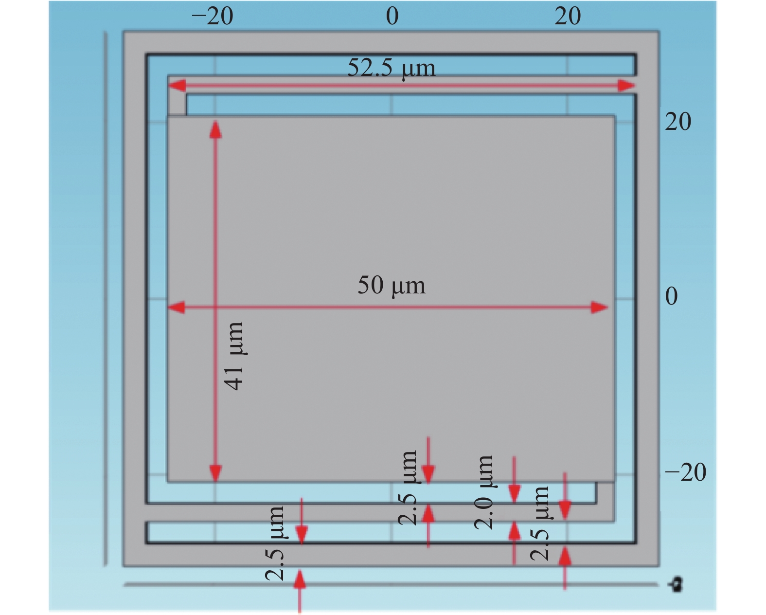
在进行芯片测试中,热量主要经过空气层向衬底进行传导,悬臂梁没有起到良好的绝热作用,致使像元无法在空气环境中实现良好的红外投影性能,为了保证其具有较稳定的热环境,红外微辐射阵列采用真空封装。
系统采用双窗口封装方案,如图7所示,可见光经真空封装上的可见光窗口进入,经反可见透红外平板后,照射在微辐射阵列上,微辐射阵列产生的红外辐射透过反可见透红外平板,透过红外窗口,由红外投影系统进行投影。

图 7 真空封装示意图
Figure 7. Schematic diagram of vacuum packaging
-
中波/长波红外镜头可以将微辐射阵列发出的中波红外辐射投影进入到离轴抛物面光学系统中,并将校正一部分离轴抛物面光学系统的像差。镜头优化时将红外窗口、反可见透红外平板、离轴抛物镜光学系统带入优化[16],表2为光学系统参数,设计结果如图8~13所示。
表 2 中波/长波红外系统参数
Table 2. Medium wave/long wave infrared system para-meters
Variable Value Band/μm 3-5
8-12Field of view/(°) 3×2.25 Focal length/mm 350 Exit pupil diameter/mm 80 Working distance/mm 160 
图 8 中波红外镜头光路图
Figure 8. Optical path diagram of medium wave infrared lens

图 9 中波红外镜头MTF图
Figure 9. MTF diagram of medium wave infrared lens
中波光学系统在1°×0.75°以内,MTF>0.5@5 lp/mm,弥散斑半径小于61 μm,具备模拟细节的能力,1°×0.75°~3°×2.25°中MTF>0.3@3.5 lp/mm,弥散斑半径小于133 μm。长波光学系统在1°×0.75°以内,MTF>0.5@5 lp/mm,弥散斑半径小于50 μm,具备模拟细节的能力,1°×0.75°~3°×2.25°中MTF>0.3@4 lp/mm,弥散斑半径小于133 μm。
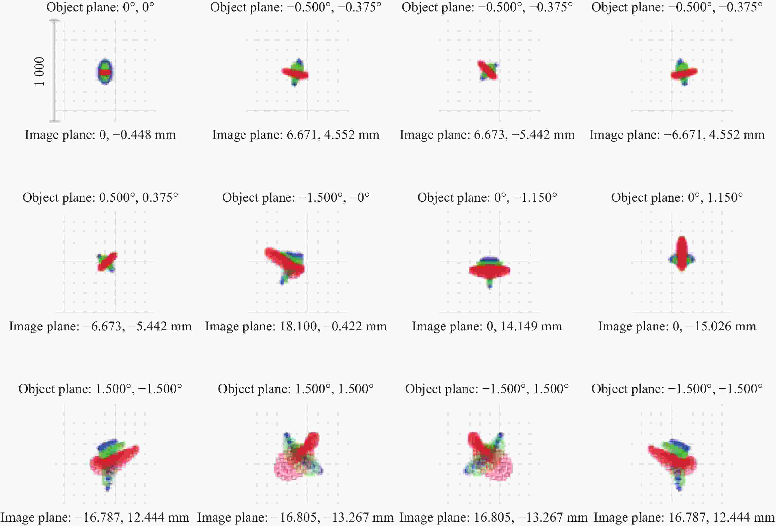
图 10 中波红外镜头点列图
Figure 10. Spot diagram of medium wave infrared lens
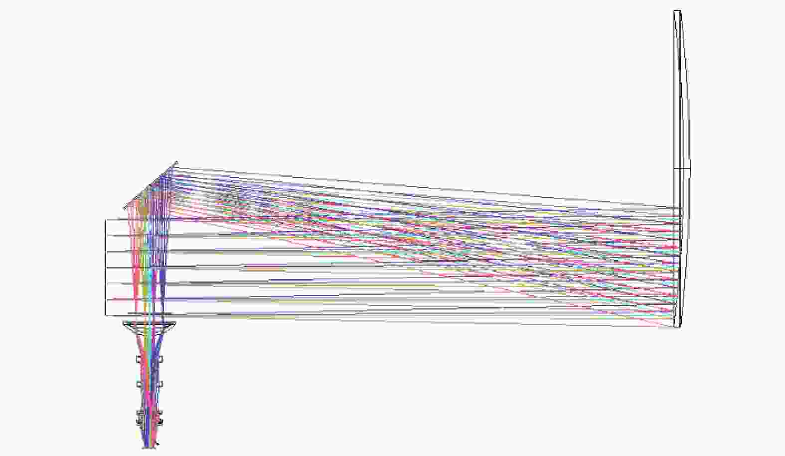
图 11 长波红外镜头光路图
Figure 11. Optical path diagram of long wave infrared lens

图 12 长波红外镜头MTF图
Figure 12. MTF diagram of long wave infrared lens
图 13 长波红外镜头点列图
Figure 13. Spot diagram of long wave infrared lens
-
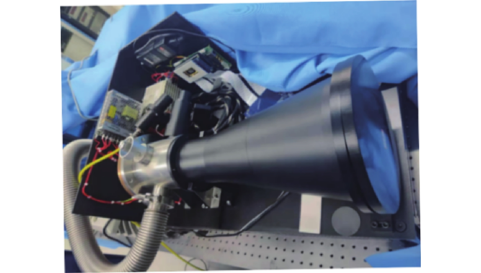
系统进行装调后,进行整机测试,整机系统实物图如图14所示,其中可见光投影为3×3的黑白格图像,图像具有不同的灰度等级,经过光学系统和微辐射阵列的反射,使用红外热像仪进行温度测试。通过改变激光器的功率,测试在不同功率下黑格和白格的温差范围,以及可以模拟的最小和最大温差,采用金属盘遮挡的方式,间断性地屏蔽光对芯片的照射,通过红外热像仪的录像功能,分析图像由明变暗或由暗变明所需的时间,从而测得芯片的帧频,测试方案如图15所示,测试结果如表3所示,最终系统模拟海上的舰船场景图如图16所示。
图 14 动态模拟装置实物图
Figure 14. Physical drawing of dynamic simulation device
图 15 测试方案
Figure 15. Test plan
表 3 测试结果
Table 3. Test result
Serial number Gray level Temperature/℃ Frequency/Hz 1 255 79.5 83 2 204 70.3 85 3 178 62.8 82 4 153 57.2 86 5 128 53.1 82 6 102 46.5 85 7 77 42.6 84 8 51 37.6 83 9 0 26.2 84 
图 16 模拟海上舰船的场景图
Figure 16. Scenarios of simulated naval vessels
-
文中通过传热方程建立了微辐射阵列芯片的理论模型,对照明光学系统和中波及长波红外系统进行设计,对芯片进行真空封装后组成了基于微辐射阵列的红外场景模拟验证系统,这种系统具有结构简单、阵列分辨率可根据目标模拟需求而进一步提高、成本低,同时帧频也因被动辐射受限于芯片自身的热传导效率等特点。通过实验结果表明:系统能够将可见光图像转换为红外图像,模拟温差大于50 K,对比度大于3:1,帧频大于80 Hz,验证了基于微辐射阵列的红外模拟技术的可行性。
Infrared dynamic scene simulator based on micro-radiation array
-
摘要: 为满足红外成像器件对目标模拟的需求,同时避免在真实环境下进行系统测试受限于人力、物力、环境等因素,提出了一种基于微辐射阵列的红外动态场景模拟技术,通过传热方程建立了芯片理论模型,并进行了仿真实验。微辐射阵列芯片采用MEMS (Micro-Electro-Mechanical System)工艺加工,阵列分辨率为1024×768,像素大小设计为60 μm×60 μm,以此为核心器件,构建了红外动态场景模拟系统样机,样机口径大于300 mm,光源使用半导体激光器替代传统的汞灯,提高了模拟器的性能。使用红外热像仪进行了测试实验,结果表明:样机可在中波红外和长波红外两个波段实现高质量的动态场景模拟,图像清晰无闪烁,其模拟温差大于50 K,对比度大于3∶1,帧频大于80 Hz。Abstract:
Objective With the rapid development of infrared detection system in military war and aerospace, it is very important to evaluate the performance of infrared detection system quickly and accurately. The system test in the real environment will increase the cost of human and material resources, and will also result in poor repeatability of test results and long test cycle due to the impact of external environment and terrain factors. Therefore, the method of infrared hardware-in-the-loop simulation based on infrared dynamic target simulator can effectively reduce the test cycle and test cost, and improve the stability of test results. At present, it mainly adopts the infrared imaging technology based on digital micro-mirror device (DMD), but the core devices of this technology are monopolized by foreign countries. Only by replacing the visible light DMD chip window, which is a complex method, can it be applied in the infrared band. Its processing technology is quite complex, which also hinders its further development. Besides, the size of DMD micro-mirror is 13 μm, which is similar to the wavelength of long-wave infrared, strong diffraction will be generated, so the infrared dynamic scene with high resolution and high contrast cannot be produced. Based on the current development, the micro-radiation array chip is designed and prepared. By converting visible light into infrared radiation, the infrared dynamic scene can be simulated with high resolution, high frame rate and wide temperature range. At the same time, the infrared dynamic scene simulation system prototype is built with this as the core device, in combination with multiple infrared shaping lenses and large aperture horizontal light tubes, which can cover conventional infrared imaging equipment, and realize high-quality dynamic scene simulation in two bands of medium and long-wave infrared. Semiconductor laser is used instead of traditional light source mercury lamp on the light source to effectively improve the simulation performance of the system, the simulated temperature difference is more than 50 K, the contrast is more than 3∶1, and the frequency is more than 80 Hz. Methods In this paper, an infrared dynamic scene simulation system based on micro-radiation array is established. The system (Fig.1) is composed of visible light projection system, infrared micro-radiation array (Fig.3), vacuum packaging system (Fig.7) and infrared lens. A theoretical model of micro-radiation array was established through heat transfer equations, and simulation experiments were conducted. By comparing the high-power semiconductor laser with the traditional mercury lamp light source, the high-power semiconductor laser is finally used as the system light source to effectively improve the contrast of the system. After analyzing the optical system, a set of complex battlefield environment infrared scene simulation and verification system based on micro-radiation array is formed after vacuum packaging. Through the whole system test (Fig.15), it can achieve high-quality dynamic scene simulation in the two bands of medium and long-wave infrared. Results and Discussions The infrared dynamic scene simulator (Fig.2) based on the micro-radiation array (Fig.3) can conduct infrared imaging in the medium wave (Fig.8) and long wave (Fig.11) through the analysis of Zemax software, and has been applied in the infrared simulation system. High-power semiconductor laser is used to replace the traditional mercury lamp light source to improve the test performance of the system. The simulated temperature difference is more than 50 K and the contrast is more than 3:1. Especially in the long-wave infrared band, it has high contrast, which makes up for the disadvantage of the low contrast in the long-wave band of the DMD system and the resolution can be further improved. The imaging results are shown (Fig.16), dynamic images can be clearly simulated. Conclusions The theoretical model of micro-radiation array chip is established by heat transfer equation, and the lighting optical system and mid-wave and long-wave infrared system are designed. After vacuum packaging of the chip, the infrared scene simulation verification system based on micro-radiation array is composed. This system has simple structure, its array resolution can be further improved according to the target simulation requirements, and the cost is low. At the same time, frame frequency is limited by the heat conduction efficiency of the chip due to passive radiation. The experimental results show that the system can convert visible image into infrared image, the simulated temperature difference is greater than 50 K, the contrast is greater than 3:1, and the frame frequency is greater than 80 Hz, which verifies the feasibility of infrared simulation technology based on micro-radiation array. -
表 1 激光器指标参数
Table 1. Laser index parameter
Item Value Power/W 200 Numerical aperture 0.24 NA Fiber core diameter/μm 200  下载: 导出CSV
表 2 中波/长波红外系统参数
Table 2. Medium wave/long wave infrared system para-meters
Variable Value Band/μm 3-5
8-12Field of view/(°) 3×2.25 Focal length/mm 350 Exit pupil diameter/mm 80 Working distance/mm 160
下载: 导出CSV
表 3 测试结果
Table 3. Test result
Serial number Gray level Temperature/℃ Frequency/Hz 1 255 79.5 83 2 204 70.3 85 3 178 62.8 82 4 153 57.2 86 5 128 53.1 82 6 102 46.5 85 7 77 42.6 84 8 51 37.6 83 9 0 26.2 84
下载: 导出CSV
-
[1] Hao Yanyun, Zhao Sunqing. Overview of hardware-in-the-loop infrared multi-band target simulation technologies abroad [J]. Infrared, 2022, 43(2): 7-14. (in Chinese) [2] Li Zhuo. Dynamic infrared image generating technique [J]. Infrared and Laser Engineering, 2006, 35(4): 388-391. (in Chinese) [3] Zhang Anjing, Wang Shicheng, Zhang Jinsheng, et al. Design of a real-time image generating system for simulation of IR imaging guidance missiles [J]. Electronics Optics & Control, 2007, 14(1): 91-95. (in Chinese) [4] Liu Shou, Liu Ningmin. Research on optical system of infrared target simulator based on TIR prism [J]. Laser & Infrared, 2016, 46(11): 1369-1374. (in Chinese) [5] Jin Huisong. Applied characterization analysis of IR-CRT and micromirror array infrared scene projector [J]. Infrared and Laser Engineering, 2008, 37(S2): 355-357. (in Chinese) [6] Dong Yanzhi, Zhou Xiaodong, Wang Changjin, et al. Progress in laser scene projector for infrared hardware in the loop testing [J]. Laser Journal, 2005(1): 6-8. (in Chinese) [7] Gao Jiaobo, Ye Kefei, Wang Jun, et al. Dynamic IR scene projection using the singlecrystal silicon liquid crystal light valve [J]. Laser & Infrared, 1999(6): 330-333. (in Chinese) [8] Liu Zhengyun, Jin Weiqi. IR scene simulation using reflective liquid crystal on silicon device [J]. Infrared Technology, 2006, 28(10): 594-598. (in Chinese) [9] Zhang Li, Feng Xiaochen, Zang Yan, et al. Real-time IR image generation and displaying system based on resistor array projector [J]. Journal of System Simulation, 2006(S2): 460-462. (in Chinese) [10] Zhong Guoli, Liao Shouyi, Yang Xinjie. Drive-and-control scheme for 512×512 MOS resistor array [J]. Infrared Technology, 2022, 44(10): 1052-1058. (in Chinese) [11] Owen M, Williams, George C, et al. History of resistor array infrared projectors: hindsight is always 100% operability[C]//Proc of SPIE, 2005, 5785: 208-224. [12] Olesona J, James J, Sparkman K, et al. Large format resistive array infrared scene projector performance & production status[C]//Proc of SPIE, 2006, 6208: 6208101. [13] William F. Characterization of digital-micromirror device-based infrared scene projector [J]. Optical Engineering, 2005, 44(8): 0864021. [14] Lippert J R, Bauchert K. Testing a new generation 512×512, >200 Hz capable, liquid crystal on silicon (LCOS) with ferro-electric liquid crystal, IR scene projector[C]//Proc of SPIE, 2006, 6208: 62080L1. [15] 贾海峰. 一维热传导方程的推导[J]. 科技信息, 2013(2): 159. doi: 10.3969/j.issn.1001-9960.2013.02.134 [16] Gao Hongwei, Yang Zhongming, Liu Hongbo, et al. Design of portable infrared target simulator system [J]. Infrared and Laser Engineering, 2023, 52(3): 20220554. (in Chinese) doi: 10.3788/IRLA20220554 -

 点击查看大图

图(16) / 表(3)
计量
- 文章访问数: 93
- HTML全文浏览量: 16
- PDF下载量: 34
- 被引次数: 0

