


-
从哈勃空间望远镜(HST)到宽视场红外巡天望远镜(WFIRST)的技术发展历程,说明美国的高分辨率光学成像有效载荷向高分辨率、大视场发展[1-2]。高分六号卫星是继高分一号卫星之后,又一兼具高分辨率成像和超大幅宽成像能力的卫星,区别于高分一号卫星多相机、多角度、视场拼接形成大幅宽观测,高分六号甚宽视场相机在国际上首次采用了自由曲面、离轴四反全反射式光学系统设计,通过单相机超大视场成像替代了传统多相机拼幅成像体制,具备860 km超大幅宽、视场角65.6°、星下点地面像元分辨率16 m的成像能力[3]。
国内外均开展了相关大视场、大口径空间相机的热设计。中国科学院长春光学精密机械与物理研究所的王洪亮等针对某日地–L2点轨道10 m口径在轨组装红外空间望远镜降温需求,设计了一个面向超大口径红外望远镜的五层遮阳罩,来自太阳的1367 W/m2的热流经过遮阳罩后降低到0.036 W/m2,望远镜温度在遮阳罩展开后通过辐射被动制冷降至50 K以下[4]。欧洲太空局(ESA) 2016年发射的大气监测仪(TROPOMI)[5],其光学前置系统由两片凹自由曲面反射镜组成,交轨视场108°,通过多层隔热组件、多级辐射制冷器联合氨、甲烷及乙烷热管,实现了大视场光学系统紫外、中波红外、短波红外探测器140~220 K的降温需求。
文中针对高分六号卫星甚宽视场相机的任务特点、空间热流环境、构型布局等约束进行热控设计,并对地面热平衡试验和在轨飞行数据进行了总结。
-
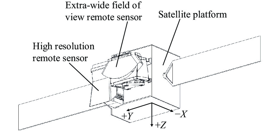
相机安装位置如图1所示,位于卫星平台+X侧,高分相机−Y侧。根据卫星坐标系定义,相机光轴对地方向为+Z向,飞行方向为+X向;安装面温度范围为−5~30 ℃,太阳帆板温度为−90~90 ℃。

图 1 高分六号卫星布局示意图
Figure 1. Layout diagram of GF-6 satellite
相机采用离轴四反光学系统,如图2所示。由框架组件、反射镜组件主镜、二四镜(次镜和四镜为一体式结构)、三镜、焦面组件和成像电箱、蒙皮组件等组成。

图 2 相机结构示意图
Figure 2. Schematic diagram of camera structure
-
相机运行于轨道高度为645 km、降交点地方时为10∶30的太阳同步轨道,寿命期间β角在16°~26°之间变化,相机姿态为三轴稳定对地;在轨运行过程中,主要受到太阳辐射、地球红外和地球阳光反照及4 K冷黑空间的交替作用[6],相机各面的到达外热流变化如图3所示,同一轨道周期内,到达相机−Y面和+X面的外热流变化较大;结合内热源位置和+Y侧高分相机的遮挡情况,散热面优选−Z面。
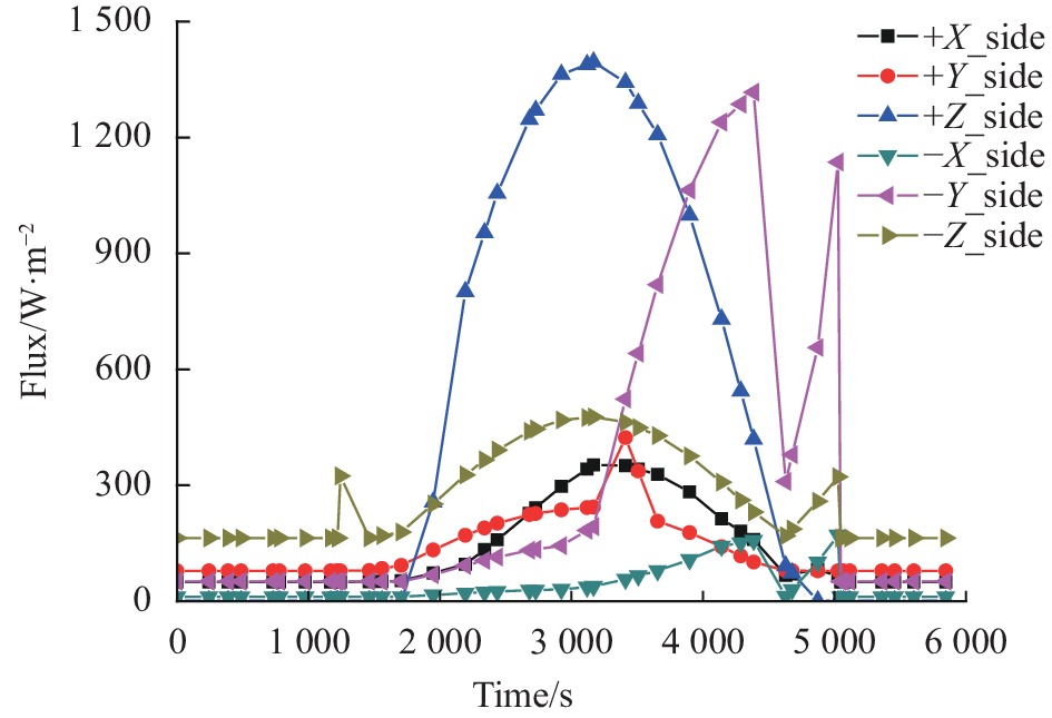
图 3 相机到达外热流
Figure 3. Incident space heat flux of camera
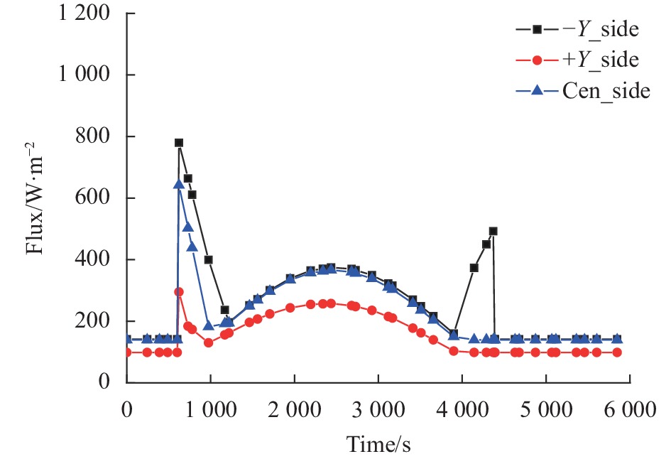
根据甚宽视场设计需求,入光口遮光罩设计成很宽的异型通光口,进出地影期间,太阳直射遮光罩内部,局部遮光罩内表面受晒时间持续5.5 min,最大热流密度为900 W/m2,受晒区域示意如图4所示。按照入光口与到达外热流的空间关系进行划分,分为+Y、+Z、−Y三部分,其在轨外热流变化如图5所示,+Y及+Z每轨太阳入射一次,−Y部分每轨太阳入射两次,入射热流引起遮光罩温度的剧烈波动,进而影响入光口临近的光学元件和主框架的温度。
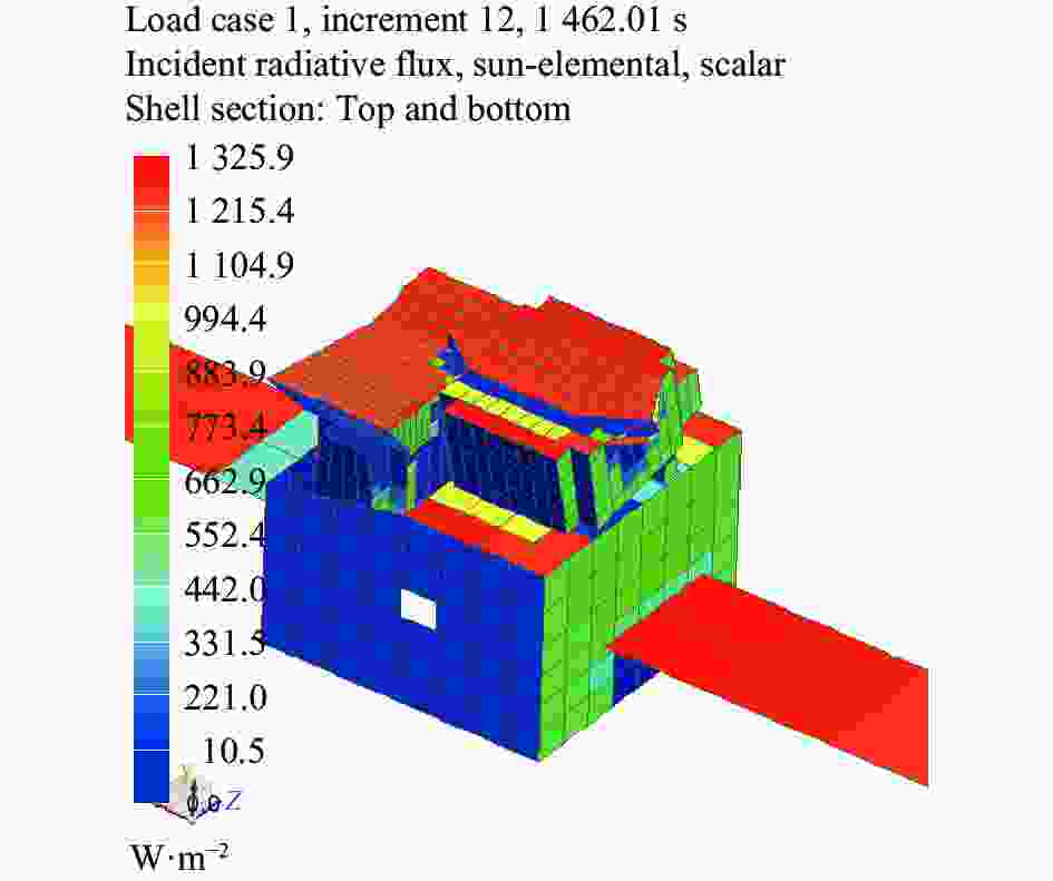
图 4 相机受晒区域
Figure 4. Sun exposure area of camera

图 5 入光口三个区域到达外热流变化
Figure 5. Change in heat flux reaching the three regions of the entrance aperture
-
为了空间布局的灵活性,拓展优化自由度,将二镜和四镜设计为一体式自由曲面构型,自由曲面为非对称结构形式,热敏感性高,即使整体温度水平均匀变化,光机结构也将产生非对称几何尺寸变化,由热引起的光学和机械误差将导致相机的视轴漂移(LOS)和波前畸变(WFE),严重影响系统的光学传递函数(MTF)。
为了确保光学系统在轨成像质量,进行了系统公差分配,以MTF下降不超过4%为基准,各反射镜面形必须优于1/60λ,主镜与二四镜间距变化不得超过2 μm,X、Y、Z向倾斜公差不超过15″。据此通过热光学分析得出主、二四镜要求在(20±0.5) ℃范围内,每轨波动不超过±0.3 ℃;三镜要求在(20±1) ℃范围内,每轨波动不超过±0.5 ℃。光学系统要求达到0.5 ℃/轨的稳定度要求。
-
相机内热源主要是焦平面组件和成像电箱,在轨工作模式分为摄像模式和待机模式。每轨摄像12 min,热耗分别为40 W和60 W;待机模式无功耗。两种模式下内热源差异明显,既要保证工作模式下能够维持CMOS器件、成像电路板等工作时不超过30 ℃,具有较低的热噪声和暗电流;又要在待机模式下具有保温能力,维持设备存储需求。
-
统筹考虑光、机、电、热的相互作用,基于相机所处空间热环境、技术指标、光机结构特点以及设计约束综合考虑。在热设计的过程中,以被动热控为主,主动热控为辅[6];在该热设计基本原则下,相机的整体热控方案如图6所示。

图 6 相机热控方案示意图
Figure 6. Diagram of thermal control scheme for camera
-
光阑蒙皮组件包括入光口遮光罩和内部光阑。入光口遮光罩组件在外表面包覆20单元多层隔热组件的基础上,内表面也包覆10单元多层隔热组件,降低了遮光罩加热区的主动加热功耗[7]。选用低反射率涂层绸(αs≥0.90, εH≥0.85)作为内表面多层面膜,避免进入相机内部杂散光增多影响相机的成像质量,如图7所示。
为了最大限度地降低−Y侧两次入射太阳外热流的影响,设计了多层面向导热增强结构,通过在低反射率涂层绸背部内衬柔性碳碳导热膜,在不降低多层法向隔热能力的同时,面向的导热能力提高10倍以上,有效降低了太阳入射热流引起的多层表面温度波动。
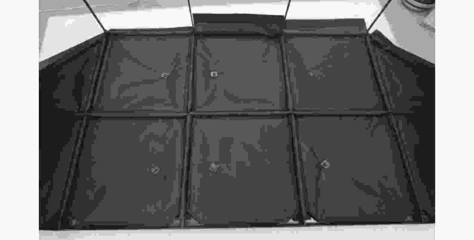
图 7 遮光罩内部包覆MLI状态
Figure 7. Status of MLI wrapped inside the hood
-
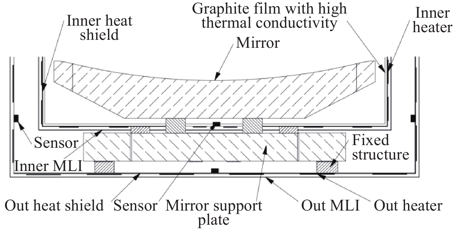
反射镜在轨的温度控制是相机成像成败的关键之一。高分四号相机[8]、某倾斜轨道相机[9-10]等多个型号通过背部设计单层加热罩的方式,控温精度达到±0.5 ℃;针对自由曲面反射镜的高温度敏感性要求,采用分级热控策略对反射镜进行热控(图8),在反射镜背部设置内、外两层辐射加热罩;外侧的辐射热控罩在反射镜支撑板背部,外表面包覆20单元多层隔热组件,内表面喷涂PNC黑漆(εH≥0.95),加热罩内侧和镜体之间形成高发射率空腔,同时热控罩表面粘贴电加热器,反射镜支撑背板的温度可以控制在(20±0.5) ℃;内辐射加热罩设置在反射镜与支撑板之间,内罩外表面包覆5单元多层,同时粘贴高导热率CC材料,增强了加热罩的温度一致性,可以避免单罩下反射镜支撑对反射镜背部的局部遮挡,通过外罩的遮挡,内罩外表面的热扰动大大降低,反射镜控温精度提高到±0.2 ℃。温精度提高到±0.2 ℃。温精度提高到±0.2 ℃。

图 8 反射镜热设计示意图
Figure 8. Diagrammatic sketch of thermal design of mirror
-
在框架主体蒙皮表面包覆多层,有效隔离瞬变的外热流及空间冷黑,减小了热量散失和交变外热流等对其产生的影响,相机内部框架表面喷涂ERB-2B消杂光黑漆(ε≥0.9),以利于其内部温度均匀化,同时进行主动加热分区设计。
框架组件的材料为铸钛合金(ZTC4),材料的导热系数为8.5 W·(m·K)–1,为了增强框架组件的热导性能,在主框架外表面粘贴面向导热系数超过1100 W·(m·K)–1、厚度为0.3 mm的高导热石墨材料(SGF2),如图9所示,处理后的主框架等效导热系数达到112 W·(m·K)–1,能够显著地提高主框架温度均匀性,减少电加热器的使用数量。

图 9 主框架粘贴石墨薄膜高导热率材料
Figure 9. Main frame paste with high thermal conductivity graphite film
-
焦面组件包含8片CMOS探测器,单片探测器功耗1.5 W,对应的驱动板功耗1 W,CMOS焦面组件总功耗20 W,每轨工作时间不超过12 min。CMOS器件热量通过设置导热压板和定位块将热量传导至焦面基板,如图10所示,导热路径热阻为1.45 ℃·W–1,可以估算单片CMOS与基板温差不超过3.6 ℃。
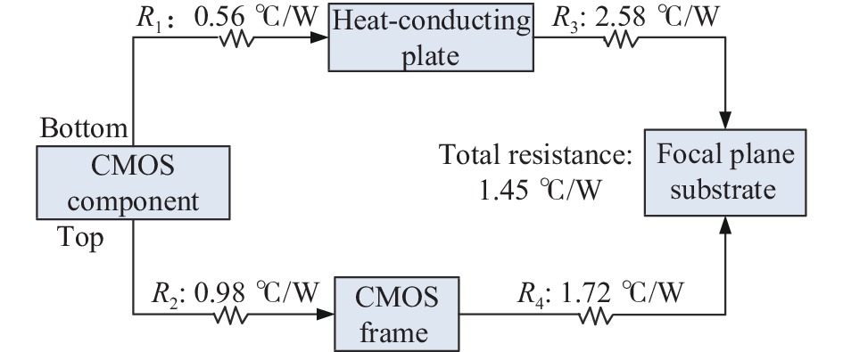
图 10 CMOS器件的导热路径
Figure 10. Heat conduction path of CMOS component
焦面基板为铝基复合材料,比热容为820 J·(kg·℃)–1,密度为2700 kg·m–3,质量为4 kg,总热容约3280 J·℃–1。整个焦平面组件与相机腔体内部的辐射换热量可表示为:
$$ \varPhi_{12}=\dfrac{{A}_{1}\left(E_{{b1}}-E_{{b2} }\right)}{{1}/{\varepsilon_{1}}+{{A}_{1}}/{{A}_{2}}\left({1}/{\varepsilon_{2}}-1\right)}=\varepsilon_{{\rm{s}}} \times 5.67\left[\left(\dfrac{T_{1}}{100}\right)^{4}-\left(\dfrac{T_{2}}{100}\right)^{4}\right] $$ (1) $$ \varepsilon_{{\rm{s}}}=\dfrac{1}{{1}/{\varepsilon_{2}}+{A_{1}}/{A_{2}}\left({1}/{\varepsilon_{2}}-1\right)} $$ (2) 式中:εs为系统的发射率;A1、A2和ε1、ε2分别为焦面组件和相机内部腔体的面积及红外发射率。
由于A2比A1大得多,即A1/A2→0,且A1为非凹表面,此时公式(1)可以简化为:
$$ {\varPhi _{12}} = {\varepsilon _1}{A_1}({E_{b1}} - {E_{b2}}) = {\varepsilon _1}{A_1} \times 5.67\left[ {{{\left(\dfrac{{{T_1}}}{{100}}\right)}^4} - {{\left(\dfrac{{{T_2}}}{{100}}\right)}^4}} \right] $$ (3) 其中,ε1取0.7,A1取0.7 m2,当焦面温度T1达到25 ℃,与20 ℃相机内部换热达到20.1 W,可知整个焦面温升不超过5 ℃。
成像电箱功耗100 W,采用石墨烯铝材制成散热结构一体化构件,如图11所示。根据PCB板上大功耗器件的位置,设计对应位置的导热凸台,直接将箱体−Z面设计成散热面;在电箱的±Y面连接两块L型铝板,在铝板表面粘贴OSR作为散热面。

图 11 大功耗器件散热路径示意图
Figure 11. Schematic diagram of heat dissipation path for high power devices
-
对相机在轨状态进行热分析仿真,统筹考虑相机与卫星平台的安装点温度、轨道外热流等热边界。仿真分析采用UG12.0/Space thermal 模块。
-
根据能量守恒原理,通过空间相机与其所处环境的热交换关系列出相机的热平衡方程组,可以建立热分析计算模型。热平衡方程组如下:
$$ \left\{ \begin{split} & {Q_1} + {Q_2} + {Q_3} = {Q_4} + Q{}_5 \\ & {Q_1} = \left( {{\alpha _{s1}}{\varPhi _{11}}S + {\alpha _{s1}}{\varPhi _{21}}{E_{r1}} + {\varepsilon _{h1}}{\varPhi _{31}}{E_{e1}}} \right){A_1} +\\ & \qquad \left( {{\alpha _{s2}}{\varPhi _{12}}S + {\alpha _{s2}}{\varPhi _{22}}{E_{r2}} + {\varepsilon _{h2}}{\varPhi _{32}}{E_{e2}}} \right){A_2} +\\ & \qquad \left( {{\alpha _{s3}}{\varPhi _{13}}S + {\alpha _{s3}}{\varPhi _{23}}{E_{r3}} + {\varepsilon _{h3}}{\varPhi _{33}}{E_{e3}}} \right){A_3} \\ & {Q_2} = \sum {{H_{ij}}({T_i} - {T_j}) + } \sum {{\varepsilon _{kl}}{\varPhi _{kl}}\sigma ({T_k}^4 - {T_l}^4)} {A_{kl}} \\ & {Q_3} = \sum {{q_i}} \\ & {Q_4} = \sum {\left({m_i}{c_i}\frac{{\partial T}}{{\partial \tau }}\right)} \\ & {Q_5} = {\varepsilon _{h1}}\sigma {T_1}^4{A_1} + {\varepsilon _{h2}}\sigma {T_2}^4{A_2} + {\varepsilon _{h3}}\sigma {T_3}^4{A_3} \\ \end{split} \right. $$ 式中:Q1为相机吸收空间热量;Q2为相机与卫星平台之间的热交换;Q3为相机内部热源;Q4为相机自身产生的能量变化;Q5为相机入光口处对冷黑空间的热辐射能量;αs1、αs2、αs3分别为遮光罩、主镜以及框架表面的太阳吸收系数;εh1、εh2、εh3分别为相机外多层、遮光罩内侧以及主镜表面的红外半球发射率;Φ11、Φ12、Φ13分别为相机外多层、遮光罩内侧以及主镜表面的太阳辐照角系数;Φ21、Φ22、Φ23分别为相机外多层、遮光罩内侧以及主镜表面的地球反照角系数;Φ31、Φ32、Φ33分别为相机外多层、遮光罩内侧以及主镜表面的地球辐照角系数;S为太阳常数,S=1353 W/m2;Er1、Er2、Er3分别为相机外多层、遮光罩内侧以及主镜表面的地球反照热流密度;Ee1、Ee2、Ee3分别为相机外多层、遮光罩内侧以及主镜表面的地球辐照热流密度;A1、A2、A3为分别为相机外多层、遮光罩内侧以及主镜表面的有效换热面积;i、j为存在接触导热关系的组部件;k、l为存在辐射导热关系的组部件;Hij为相机内部组部件;T为光学相机内部组部件的温度;εkl为光学相机内部组部件表面发射率;Φkl为光学相机内部组部件辐射角系数;σ为玻耳兹曼常数,σ=5.67×10−8 W/(m2·K4);Akl为相机内部组部件参与辐射换热的有效面积;qi为相机内部热源;mi为相机内部组部件质量;ci为相机内部组部件热容量。
-
有限元建模遵循几何等效和热容等效的原则,基于结构模型进行CAE建模,在热容等效的前提下进行模型简化[11-12],忽略了螺孔、倒角等细小特征,在不影响传热路径的情况下,忽略不关注热分布的零件,采用设置热耦合的方式简化传热路径,正确反映热量的传递,共建立117个热耦合;手动划分7587个节点、7844个单元,有限元模型如图12所示。

图 12 相机的有限元模型
Figure 12. Finite element model of camera
-
分析工况选取主要考虑相机相对于空间热环境的位置、飞行姿态、内热源、热控涂层退化、卫星安装边界条件5个方面的变化[13-14]。根此设置相机在轨极端低温、极端高温两个工况,如表1所示。
表 1 热分析工况设置
Table 1. Thermal analysis condition setting
Case β angel/(°) Surface coating Operating mode Temperature boundary Cold
Hot16.92
27.15Early
EndIn operation
12 min/orbit−5
30 -
相机反射镜组件和电子学组件瞬态温度变化如图13所示。由分析结果可知,低温工况下主镜、二四镜、三镜的温度波动分别为19.83~20.10 ℃、19.80~20.13 ℃、19.91~20.04 ℃;高温工况下主镜、二四镜、三镜的温度波动分别为19.88~20.10 ℃、19.81~20.14 ℃、20.02~20.20 ℃;反射镜组件温度稳定,高、低温工况下温度波动不超过±0.2 ℃。非摄像期间,CMOS组件温度为19.5~19.8 ℃;摄像期间,CMOS组件温度为19.6~23.6 ℃,CMOS焦面组件温度波动不超过4.5 ℃,成像电箱温度波动不超过8 ℃。

图 13 反射镜及电子学组件瞬态温度变化
Figure 13. Transient temperature change of mirror and electric component
-
通过热平衡试验数据与热分析结果对比,能够找出热分析模型建立、材料属性、载荷和边界条件等方面的不足[15-16],可以验证仿真分析的正确性和温度预示的有效性,并对热设计优化提供指导。
-
整机热平衡试验在ZM4300 空间模拟器中进行,空间模拟器内压力≤1.3×10⁻³ Pa,热沉温度(100±5) K。热平衡试验现场如图14所示。

图 14 相机热平衡试验
Figure 14. Thermal balance test of camera
卫星平台、太阳帆板、高分相机均使用模拟件,其中卫星平台安装板、高分相机使用闭环控温提供温度边界。采用多层内表面粘贴加热片的方式模拟相机吸收外热流,使用红外加热笼模拟入光口到达外热流,并在相机入光口布置热流计进行热流密度的监测与闭环控制。
-
相机整体温度水平的热分析结果与热试验结果对比见表2。可以看出,试验过程中主镜、二四镜温度不变,三镜温度波动0.23 ℃,热分析与热试验结果对比最大偏差均在5%以内。通过热分析结果与热试验结果对比可见,两者结果吻合较好,验证了热分析结果的有效性。
表 2 热分析结果与热平衡试验结果对比
Table 2. Comparison between thermal analysis and thermal balance test
Position Hot case Cold case Analysis/℃ Thermal balance test/℃ Max deviation Analysis/℃ Thermal balance test/℃ Max deviation Primary mirror 19.82-20.10 20.06 1.20% 19.72-20.10 20.06 1.50% Second and forth mirror 19.77-20.12 19.99 1.10% 19.76-20.12 19.99 1.10% Third mirror 19.90-20.20 20.1 0.99% 19.90-20.04 19.78-20.1 1.43% CMOS 19.92-23.10 20.12-22.82 1.39% 19.32-19.90 18.82-19.26 3.40% Imaging electric box 13.68-20.62 13.78-19.08 4.06% 14.22-15.12 14.88 4.44% -
高分六号卫星于2018年6月2日成功发射,至6月7日统计了100圈在轨延遥和时遥数据:主镜温度19.99 ℃,二四镜温度20.06 ℃,三镜温度19.75~20.12 ℃,主框架温度19.95~20.12 ℃,焦面温度温度稳定在19.92~23.46 ℃,成像电箱温度14.67~18.68 ℃,完全满足光机组件温度水平和稳定性要求。
-
文中针对甚宽视场空间相机结构特点和入光口外热流剧烈变化带来的热控制难度,给出了合理的热设计方案,对相机不同部位的部件实施了针对性热控措施,满足了异形大通光口径离轴自由曲面相机在轨的热控指标要求。并与整机热平衡试验结果进行了对比分析,验证了热设计方案的有效性和可行性。所采用的热控措施技术成熟、可操作性高。相关热控措施和热设计方法适用于甚宽视场空间光学相机的热设计。
Thermal control design and verification of extra-wide field-of-view camera for GF-6 satellite
-
摘要: 甚宽视场相机作为高分六号卫星的核心载荷,具备65.6°视场、862 km超大幅宽和8谱段成像能力。针对其自由曲面离轴四反光学系统的结构特点和任务需求,采用复合型多层隔热组件进行热隔离、高导热率石墨膜进行热疏导及分级热控等措施进行了热控设计,实现了光机结构的精密控温和高热耗/热流密度电子学设备的高效散热,并利用有限元分析软件UG12.0/Space thermal仿真分析了相机高、低温工况下的温度;通过对比热分析、热试验及卫星在轨遥测温度数据,验证了该热控方案的实际效果。在轨遥测数据显示:光机结构在轨温度水平为19.7~20.3 ℃,温度梯度最大不超过0.4 ℃,CMOS焦面组件每轨摄像12 min的情况下,温度波动在19~24 ℃,均满足热控指标要求,遥测数据与热分析及热试验结果偏差小于±0.5 ℃。表明该相机热设计正确可行,热分析及热试验过程合理可靠。Abstract:
Objective The extra-wide field-of-view camera adopts an off-axis four-mirror optical system, and the second and forth mirror adopt an integrated free-form surface structure. A free-form surface is an asymmetric structure that is highly sensitive to thermal changes. Even with a uniform change in bulk temperature, the optical-mechanical structure still undergoes asymmetric geometric changes. In addition, the extra-wide field-of-view camera needs to meet the design requirements of a width of 860 km and a field of view of 65.6°, and the entrance mask adopts a wide special-shaped opening design. The sun shines directly on the inside of the hood for a duration of 5.5 minutes as it enters and exits the Earth's shadow. Both optical and mechanical errors are caused by heat cause line of sight drift (LOS) and wavefront distortion (WFE) in the camera. These issues seriously affect the optical transfer function of the system. Considering its structural characteristics and the thermal control challenges brought about by the large change of heat flow outside the light entrance, targeted thermal control measures must be taken for different parts of the camera to meet the thermal control index requirements of off-axis free-form surface cameras with special-shaped optical apertures in orbit. Methods Six aspects of the camera are analyzed, including its on-orbit state, structural layout, task requirements, orbital environment, technical indicators, and heat sources. The thermal control design is implemented by using composite multi-layer heat insulation components for thermal isolation (Fig.7), graded thermal control for mirrors (Fig.8), and high thermal conductivity graphite film for thermal conduction (Fig.9). This design allows for precise control of the optical-mechanical structure and efficient heat dissipation of high heat consumption/heat flux electronic equipment. The temperature of the camera is simulated and analyzed under high and low temperature conditions using the finite element analysis software UG12.0/Space thermal. The effectiveness of the thermal control scheme is verified through thermal analysis, thermal test, and satellite on-orbit telemetry temperature data. Results and Discussions The transient temperature changes of the camera mirror assembly and electronic components are presented. Under low temperature conditions, the primary mirror exhibits a temperature fluctuation ranging from 19.83 ℃ to 20.10 ℃, while the second and fourth mirrors experience a temperature fluctuation between 19.80 ℃ and 20.13 ℃. The temperature fluctuation of the third mirror falls within the range of 19.91 ℃ to 20.04 ℃ (Fig.13(a)). Similarly, under high temperature conditions, the temperature fluctuation of the primary mirror ranges from 19.88 ℃ to 20.10 ℃, while the second and fourth mirrors exhibit a fluctuation between 19.81 ℃ and 20.14 ℃. The temperature fluctuation of the third mirror ranges from 20.02 ℃ to 20.20 ℃ (Fig.13(b)). It is worth noting that the reflector assembly maintains a stable temperature, with fluctuations not exceeding ±0.2 ℃ under both high and low temperature conditions. During the non-camera period, the CMOS component maintains a temperature range of 19.5 ℃ to 19.8 ℃ (Fig.13(c)). However, during the imaging period, the temperature of the CMOS component varies between 19.6 ℃ and 23.6 ℃. The temperature fluctuation of the CMOS focal plane component does not exceed 4.5 ℃, and the imaging electrical box experiences a temperature fluctuation within 8 ℃ (Fig.13(d)). The overall temperature level of the camera, as determined by thermal analysis, is compared with the thermal test results (Tab.2). The table shows that the temperature of the primary mirror and the second and fourth mirrors remained constant during the test, while the temperature of the third mirror fluctuated by 0.23 ℃. The maximum deviation between the thermal analysis and thermal test results is within 5%. The comparison of the thermal analysis results with the thermal test results confirms the validity of the thermal analysis. Conclusions The deviation between the on-orbit telemetry data and the thermal analysis and thermal test results is within ±0.5 ℃. This indicates that the thermal design of the camera is accurate and feasible, and the thermal analysis and test process are reasonable and reliable. The employed thermal control measures and design methods are suitable for the thermal design of extra-wide space optical camera. -
图 5 入光口三个区域到达外热流变化
Figure 5. Change in heat flux reaching the three regions of the entrance aperture
图 9 主框架粘贴石墨薄膜高导热率材料
Figure 9. Main frame paste with high thermal conductivity graphite film
图 11 大功耗器件散热路径示意图
Figure 11. Schematic diagram of heat dissipation path for high power devices
图 13 反射镜及电子学组件瞬态温度变化
Figure 13. Transient temperature change of mirror and electric component
表 1 热分析工况设置
Table 1. Thermal analysis condition setting
Case β angel/(°) Surface coating Operating mode Temperature boundary Cold
Hot16.92
27.15Early
EndIn operation
12 min/orbit−5
30 下载: 导出CSV
表 2 热分析结果与热平衡试验结果对比
Table 2. Comparison between thermal analysis and thermal balance test
Position Hot case Cold case Analysis/℃ Thermal balance test/℃ Max deviation Analysis/℃ Thermal balance test/℃ Max deviation Primary mirror 19.82-20.10 20.06 1.20% 19.72-20.10 20.06 1.50% Second and forth mirror 19.77-20.12 19.99 1.10% 19.76-20.12 19.99 1.10% Third mirror 19.90-20.20 20.1 0.99% 19.90-20.04 19.78-20.1 1.43% CMOS 19.92-23.10 20.12-22.82 1.39% 19.32-19.90 18.82-19.26 3.40% Imaging electric box 13.68-20.62 13.78-19.08 4.06% 14.22-15.12 14.88 4.44%
下载: 导出CSV
-
[1] 刘韬, 龙亮. 从“宽视场红外巡天望远镜”分析美军光学成像侦察卫星的技术发展[J]. 国际太空, 2016, 455: 39-43. [2] Zhang Xuejun, Fan Yanchao, Bao He. Applications and development of ultra large aperture space optical remote sensors [J]. Optics and Precision Engineering, 2016, 24(11): 2613-2626. (in Chinese) [3] 陆春玲, 白照广, 李永昌. 高分六号卫星技术特点与新模式应用[J]. 航天器工程, 2021, 30(01): 7-14. Lu Chunling, Bai Zhaoguang, Li Yongchang, et al. Technical characteristic and new mode applications of GF-6 satellite [J]. Spacecraft Engineering, 2021, 30(1): 7-14. (in Chinese) [4] 王洪亮, 郭亮, 熊琰. 超大口径在轨组装红外望远镜遮阳罩热设计[J]. 红外与激光工程, 2019, 48(12): 202-207. Wang Hongliang, Guo Liang, Xiong Yan, et al. Thermal design of ultra-large diameter in-orbit assembly infrared telescope sunshield [J]. Infrared and Laser Engineering, 2019, 48(12): 1214001. (in Chinese) [5] Zevenbergen P, Doornink J, Butters T, et al. Thermal design of the sentinel 5 precursor TROPOMI instrument [C]//42nd International Conference on Environmental Systems, 2012. [6] 于善猛, 刘巨, 杨劲松. 离轴式空间光学相机的热设计及仿真研究[J]. 红外与激光工程, 2011, 40(8): 1521-1525. doi: 10.3969/j.issn.1007-2276.2011.08.027 Yu Shanmeng, Liu Ju, Yang Jinsong, et al. Thermal design and simulation for off-axis space optical remote sensor [J]. Infrared and Laser Engineering, 2011, 40(8): 1521-1525. (in Chinese) doi: 10.3969/j.issn.1007-2276.2011.08.027 [7] 江帆, 吴清文, 王忠素. 空间相机遮光罩的低功耗热设计[J]. 红外与激光工程, 2016, 19(6): 0918002-1~0918002-6. Jiang Fan, Wu Qingwen, Wang Zhongsu, et al. Thermal design of space camera baffle with low power [J]. Infrared and Laser Engineering, 2016, 45(9): 0918002. (in Chinese) [8] Yu Feng, Xu Nana, Zhao Yu, et al. Thermal design and test for space camera on GF-4 satellite [J]. Spacecraft Recovery & Remote Sensing, 2016, 37(4): 72-79. (in Chinese) [9] Shen Chunmei, Yu Feng, Liu Wenkai, et al. Thermal design of one space gas monitoring sensor and test validation [J]. Infrared and Laser Engineering, 2020, 49(4): 0413007. (in Chinese) doi: 10.3788/IRLA202049.0413007 [10] Yu Zhi, Meng Qingliang, Yu Feng, et al. Thermal design and test for space camera on inclined-LEO orbit [J]. Infrared and Laser Engineering, 2021, 50(5): 20200332. (in Chinese) [11] 麻慧涛, 华诚生. 通信卫星平台的热分析建模准则 [C]//第五届空间热物理会议论文集. 北京: 中国宇航学会, 2000: 189-195. [12] Yang Xianwei, Wu Qingwen, Li Shunsheng, et al. Thermal design of space optical remote sensor [J]. Chinese Optics, 2011, 4(2): 140-146. (in Chinese) [13] 郭亮, 吴清文, 颜昌祥. 空间光谱成像仪热设计及其分析与验证[J]. 光学精密工程, 2011, 19(6) 1272-1279. doi: 10.3788/OPE.20111906.1272 Guo Ling, Wu Qingwen, Yan Changxiang, et al. Thermal design of space spectral imaging apparatus and its analysis and verification [J]. Optics and Precision Engineering, 2011, 19(6): 1272-1279. (in Chinese) doi: 10.3788/OPE.20111906.1272 [14] 韩冬, 吴清文. 空间相机热设计中极端工况的确定[J]. 光学技术, 2009, 35(6): 843~850. doi: 10.3321/j.issn:1002-1582.2009.06.003 Han Dong, Wu Qingwen. Determination of extreme working conditions for attitude-varied space camera in thermal design [J]. Optical Technique, 2009, 35(6): 843-850. (in Chinese) doi: 10.3321/j.issn:1002-1582.2009.06.003 [15] Peter G, Erik F. Design guidelines for thermal stability in opt-mechanical instruments [C]//SPIE, 2003, 5176: 126-134. [16] 江利丰, 傅伟纯, 陈建新. 高分辨率相机精密热控设计及试验[J]. 宇航学报. 2014, 35(4): 467-473. Jiang Lifeng, Fu Weichun, Chen Jianxin, et al. Precise thermal control design and test for the high-resolution three-linear array mapping cameras [J]. Journal of Astronautics, 2014, 35(4): 467-473. (in Chinese) -

 点击查看大图
计量
- 文章访问数: 87
- HTML全文浏览量: 15
- PDF下载量: 35
- 被引次数: 0

