


-
太阳能是人类开发利用清洁能源的重要方向之一[1-2]。大气的吸收、反射、散射作用削弱了太阳光到达地面的辐射强度,如要高品质利用太阳能,需要先聚光再利用。目前,太阳能反射式聚光技术主要有塔式、槽式、线性菲涅耳式以及碟式四种方式[3-6]。线性菲涅耳式聚光器具有结构简单、近地安装、抗风载能力强、国产化程度高、建造成本低等优点,也被称为离散化了的槽式聚光器,在太阳能光热利用领域有着广阔的应用前景[7-9]。兰州交通大学国家绿色镀膜工程中心研发的熔盐线性菲涅耳式光热发电技术已在国家首批太阳能光热发电示范项目——敦煌大成50 MW熔盐线性菲涅耳式太阳能光热发电示范项目中规模化应用,聚光器光学性能表现优异[10]。
线性菲涅耳式聚光器(Linear Fresnel Reflector, LFR)主要由一次反射镜、二次反射接收器和跟踪控制装置构成。太阳光经过多列一次反射镜反射进入到二次反射镜开口,再经二次反射镜汇聚到接收器(吸热管)上,加热吸热管中的传热介质完成太阳辐射向热能的转换[11],因此二次反射接收器的性能及运行状态对整个LFR系统至关重要。集热管内传热介质流速较慢不能有效形成湍流时,集热管表面能流密度非均匀分布将容易致使集热管局部“热斑”,尤其介质半管或者空管运行时,能流密度的均匀分布将显得更为必要[12]。Häberle等[13]对单管复合抛物面(CPC)接收器中的吸热管表面辐射能流的研究结果表明,吸热管表面的辐射能流分布很不均匀,绝大部分辐射集中在吸热管下半部。Moghimi等[14]对腔体接收器的能流分布进行了仿真研究,结果表明集热管表面能流周向分布不均匀,吸热管周向存在较大的温度梯度,会导致集热管出现弯曲的现象。Eck等[15]的研究表明,LFR系统中吸热管局部温度达到了569 ℃,该温度远超涂层的耐受温度。Lu等[16]针对槽式系统的传热性能进行了研究,结果表明,由于非均匀辐射的能流分布,吸热管发生明显的弯曲变形,极端情况下,金属管会顶破玻璃管而使得真空管失真空。上述原因导致的真空管破损在课题组建成的多个示范项目中时有发生,成为集热系统安全运行的最大隐患。线性菲涅耳式太阳能聚光系统常用瞄准策略是单线策略,即所有反射镜都聚焦在集热管中心线上。Eck等[15]提出可以通过逐次偏移主反射镜的方式来减小能流分布非均匀性,但这样会显著牺牲系统光学效率。邱羽等[17]基于光线跟踪和遗传算法提出了一种以光学效率和能流分布不均匀度作为目标函数,瞄准线均匀分布在接收平面上的多线瞄准策略,得到了与Eck等人相近的结论。
综上所述,LFR集热系统中采用单线瞄准策略会导致能流分布不均,系统运行存在安全隐患,现有的多线瞄准策略在改善能流分布均匀性的同时又会降低系统光学效率。针对上述问题,文中基于Tonatiuh光学仿真软件建立线性菲涅耳式聚光器的模型,探讨一次反射镜焦距与光斑宽度的关系以及瞄准点位置的选择对光斑宽度的影响等,以期探索一种能兼顾系统光学效率与能流均匀分布的瞄准策略,为线性菲涅耳式太阳能聚光器的优化设计和评价提供依据。
-
LFR系统结构示意图如图1所示。接收器固定放置于距一次镜场所在平面高H处,第n列镜子与水平面形成的夹角为θn。反射镜中心与镜场中心的距离为Qn,与n−1列镜子中心的距离为Sn。文中采用无阴影镜场布置方式[18],相关表达式为:

图 1 线性菲涅耳式聚光器结构示意图
Figure 1. Structural diagram of linear Fresnel condenser
$$ \tan \left( {\pi - \alpha - 2{\theta _n}} \right) = {H \mathord{\left/ {\vphantom {H {{Q_n}}}} \right. } {{Q_n}}} $$ (1) $$ {S_n} = \frac{{{W_m}}}{2}\left[ {\frac{{\left( {\sin {\theta _n} + \sin {\theta _{n - 1}}} \right)}}{{\tan \alpha }} + \cos {\theta _n} + \cos {\theta _{n - 1}}} \right] $$ (2) $$ {Q_n} = {Q_{n - 1}} + {S_n},n \geqslant 1 $$ (3) 其中,二次反射镜面型为渐开线+抛物线的形式[19-21],LFR参数如表1所示。
表 1 LFR系统参数
Table 1. Linear Fresnel system parameter
Parameter Value Width of the mirror, Wm/m 0.8 Length of the mirror, Lm/m 4 Number of mirrors, nm 16 Distance between adjacent mirrors, Sn/m 0.332 Height of receiver, H/m 9.056 Diameter of the tube/mm 90 Half acceptance angle of CPC, θc/(o) 45 Aperture width of CPC/mm 400 -
LFR中一次反射镜采用曲面镜代替平面反射镜可以降低反射光线在二次反射镜开口处的溢出率,从而提高系统光学效率。一次反射镜与接收器的距离相对固定,曲面反射镜的焦距决定其在接收器开口位置所形成光斑的宽度。
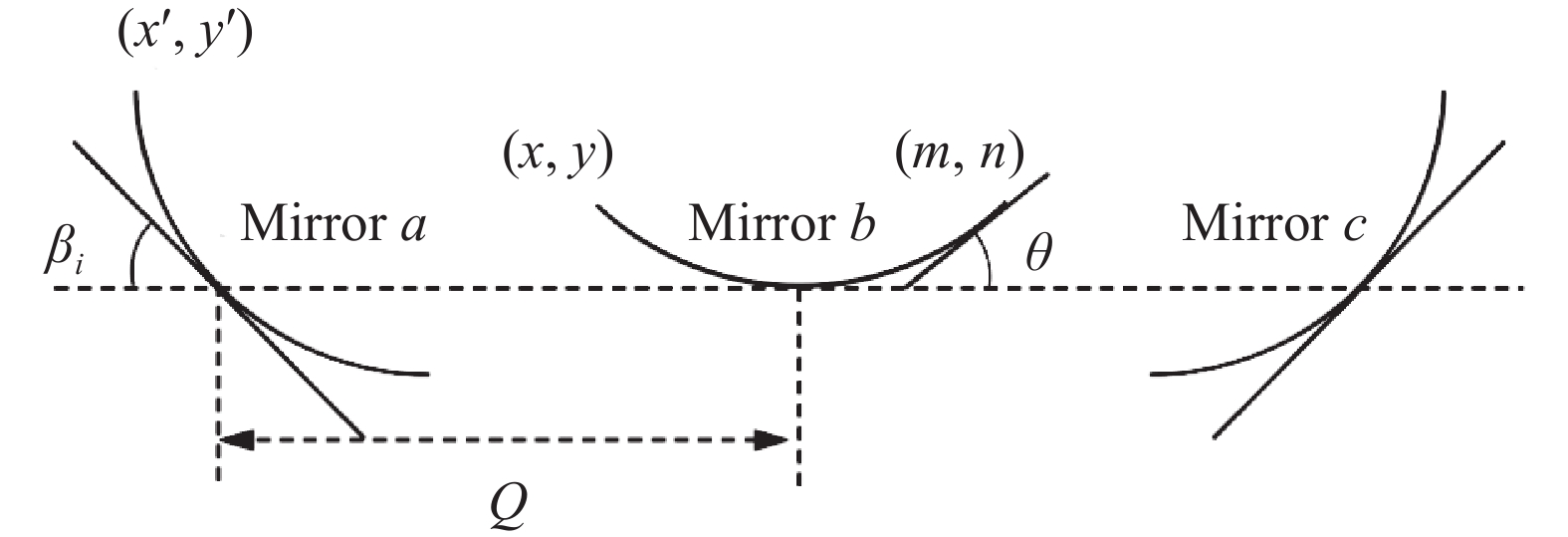
以常用的圆柱面镜子为研究对象。镜面水平放置,以镜面最低点为原点建立坐标系,如图2所示。反射镜右侧边缘点(m, n),圆柱面镜半径$ {r}{=(}{{m}}^{{2}}{+}{{n}}^{{2}}{)/} 2{n} $,右边缘点的切角$\theta {=-}{{a\rm{tan}}(}{-}{m}{/(}{n}{-}{r}{))}$,圆柱面相对高度定义为反射镜开口平面相对于镜面最低点的高度。镜场中其余反射镜的偏转角度与坐标位置均可由原点位置水平放置的反射镜旋转和平移所得到。以反射镜a为例,已知其偏转角为βi,在系统中坐标位置为Qi,已知反射镜b左边缘坐标为(x, y)的情况下,由旋转平移变换可得到a镜左侧边缘点的坐标为:

图 2 反射镜变换示意图
Figure 2. Schematic diagram of mirror transformation
$$ \left\{ {\begin{array}{*{20}{c}} {{x^\prime } = x\cos \left( { - {\beta _i}} \right) - y\sin \left( { - {\beta _i}} \right) - {Q_i}} \\ {{y^\prime } = y\sin \left( { - {\beta _i}} \right) + y\cos \left( { - {\beta _i}} \right)} \end{array}} \right. $$ (4) 经变换后,a镜的左边缘切角为$\theta _i^\prime $=βi−θ,求得在左边缘的反射光线角度和在高度H处光斑点的横坐标为:
$$ {\varphi _a} = \pi - \gamma - 2\theta _i^\prime $$ (5) $$ x{l_a} = \frac{{\left( {H - {y^\prime }} \right)}}{{\tan (\varphi )}} + {x^\prime } $$ (6) 同理,对于右侧的c镜,左边缘切角为$\theta _i^\prime $=βi+θ,左边缘的反射光线角度和在高度H处光斑点的横坐标为:
$$ {\varphi _b} = \gamma + 2\theta _i' $$ (7) $$ x{l_b} = \frac{{\left( {H - {y^\prime }} \right)}}{{\tan ( - \varphi )}} - {x^\prime } $$ (8) 右侧边缘点在H处光斑点的横坐标xr同理可以求得,xl与xr之间的距离为反射镜在高度H处形成的光斑宽度。依次得到镜场中其余反射镜的光斑宽度后,将每列反射镜左右边缘点在H处形成的两个光斑点组成一个集合,计算集合中最大值与最小值的差值,即可得到一次镜场在H处所形成的光斑宽度。不同焦距下理论最大光斑宽度如图3所示。
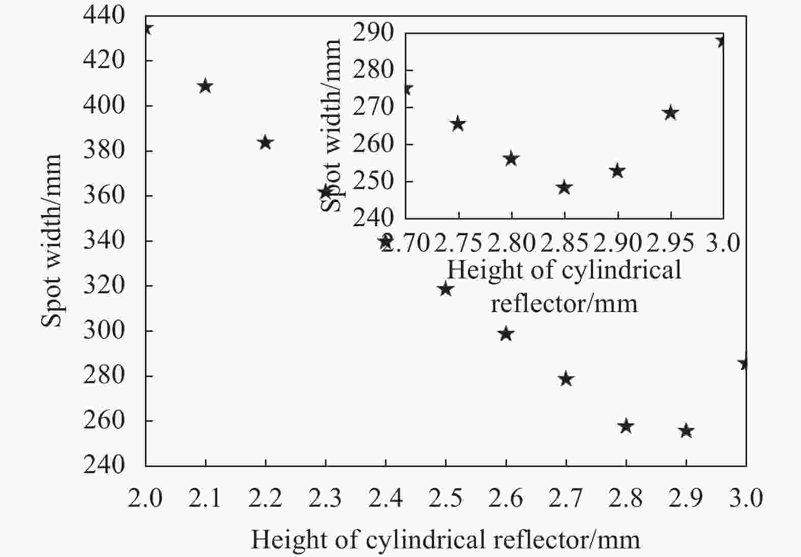
图 3 反射镜焦距与光斑宽度关系图
Figure 3. Relationship between the focal length of the mirror and the width of the spot
从图3可以看出,相对高度为2.85 mm的反射镜面在H处所形成的光斑宽度最小为249 mm,此时的光斑宽度远小于二次镜开口宽度400 mm。
-
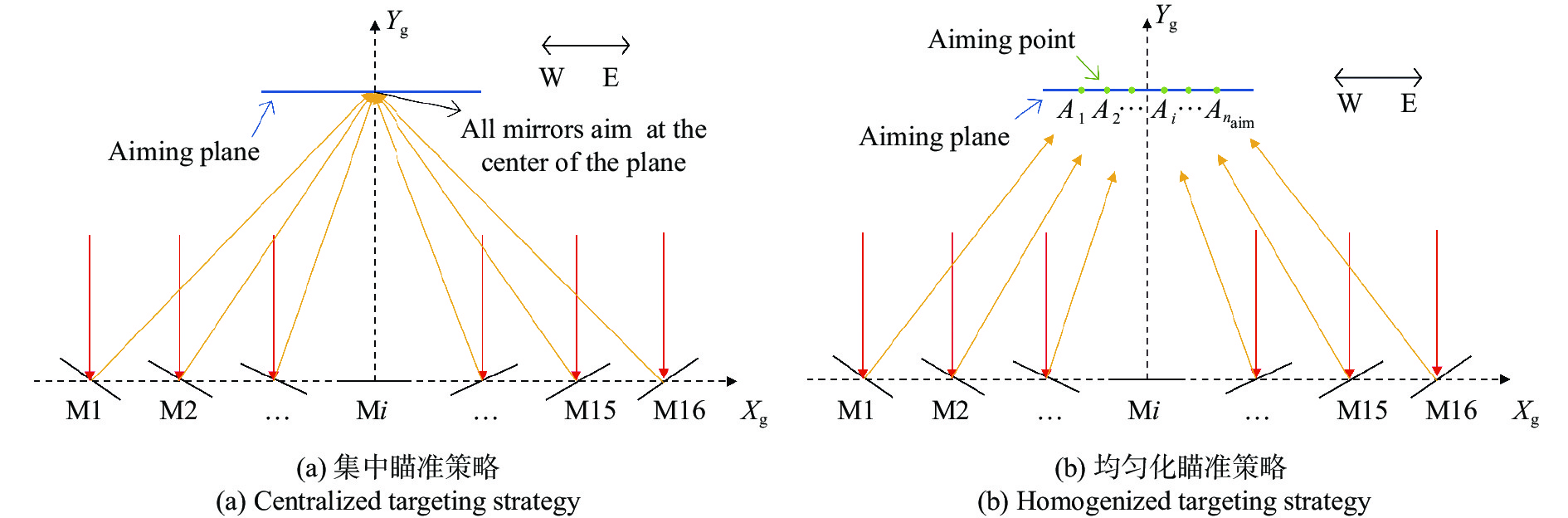
选择相对高度为2.85 mm的一次反射镜研究瞄准策略。一次反射镜在接收器中瞄准点的位置决定了光线进入接收器的数量与入射角度。图4(a)所示为单线瞄准线策略,瞄准平面位于集热管中心水平面位置,一次反射镜场中所有镜子的瞄准点都集中在平面中心点上。瞄准点均匀分散在瞄准平面上(图4(b)),自西向东依次进行以A1~An编号,瞄准点坐标定义为An (xaim, yaim)。瞄准点在瞄准平面上的位置不同,在接收器开口处所形成的光斑宽度也不同。xaim为一次反射镜在瞄准平面最右侧瞄准点,与最左侧瞄准点关于Yg轴对称。

图 4 两种瞄准策略示意图
Figure 4. Schematic diagram of two aiming strategies
由图5可知,瞄准点xaim距集热管中心越远,形成的光斑宽度也越大。当xaim在0.03~0.04 m之间,光斑宽度接近400 mm。xaim大于0.04 m后,光斑宽度超过CPC开口宽度,部分入射光线溢出接收器,系统光学效率下降。

图 5 瞄准点位置与光斑宽度示意图
Figure 5. Schematic diagram of aiming point position and spot width
-
一次反射镜场东西对称布置(图4),反射镜由西向东依次命名为M1~M16。根据每列反射镜瞄准点的横坐标xaim位置(yaim=9.056)设计了五种瞄准策略,数据如表2所示。其中,策略1中瞄准点集中在集热管圆心位置(国家首批光热发电示范项目——敦煌大成50 MW熔盐线性菲涅耳式光热发电示范项目采用的瞄准方案)。策略4与策略5的瞄准点均匀在瞄准平面中心两侧,策略2与策略3为东西两侧瞄准点分别聚集在策略4与策略5区间的两端,以对比分析瞄准点分散与聚集的差异性。
表 2 五种瞄准策略
Table 2. Five aiming strategy
Aiming
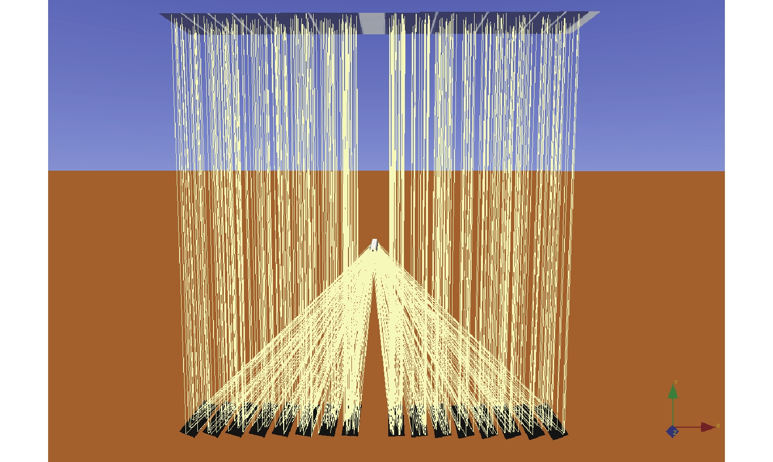
strategyxaim/m M1 M2 M3 M4 M5 M6 M7 M8 1 0.00 2 0.035 3 0.07 4 −0.035 −0.025 −0.015 −0.005 0.005 0.015 0.025 0.035 5 −0.07 −0.05 −0.03 −0.01 0.01 0.03 0.05 0.07 使用Tonatiuh仿真软件对五种不同瞄准策略建立了LFR模型。依据公式(1)~(3)设置反射镜在镜场中坐标位置,将反射镜形状设置为“圆柱面”,每列反射镜追踪类型设置为“线性菲涅耳追踪器”,主动轴设置为“Z轴”,瞄准点坐标设置为“(xaim, 9.056)”,xaim根据不同的瞄准策略与镜子的位置,具体参数设置如表2所示。集热管形状设置为“圆柱形”,二次反射镜通过Matlab软件计算相关参数后由CAD软件建模并导入Tonatiuh,设置光线追迹数量为100000条,太阳辐射强度为1000 W/m2。为便于研究,将模型中所有反射镜反射率设置为1,集热管表面吸收率设置为1。所建LFR模型如图6所示。

图 6 Tonatiuh构建的线性菲涅耳式聚光系统
Figure 6. Linear Fresnel concentrating system built with Tonatiuh
-
定义系统瞬时光学效率η为:
$$ \eta = {Q_c}/(DNI \cdot {L_m}{W_m}{n_m}) $$ (9) 式中:Qc与DNI分别为集热管吸收涂层吸收的能量和太阳直射辐射强度;Lm为一次反射镜长度;Wm为反射镜宽度;nm表示镜子数量。
集热管周向局部聚光比LCR定义为:
$$ LCR = {q_k}/DNI $$ (10) 式中:qk为集热管周向第k个网格的局部能流密度。
将集热管表面划分为Nc个网格,通过比较各网格内接收光子的差异性来表征集热管表面能流分布的均匀性。集热管能流分布标准差σ越小,能流差异性越小,能流分布越均匀;反之,能流差异性越大,能流分布越不均。
$$ \sigma = \dfrac{{\sqrt {\dfrac{1}{{{N_c}}}\displaystyle\sum\limits_{k = 1}^{{N_c}} {{{\left( {{q_k} - \mu } \right)}^2}} } }}{\mu } $$ (11) $$ \mu = \frac{1}{{{N_c}}}\sum\limits_{k = 1}^{{N_c}} {{q_k}} $$ (12) 式中:μ表示集热管表面所有网格能量的平均值。
-
不同瞄准策略下二次反射接收器集热管表面能流分布如图7所示。以集热管左半部中间位置为X轴原点,顺时针展开集热管表面,X轴为集热管截面圆周长度方向,Y轴为集热管长度方向。对比分析图7 (a)与图7 (b),瞄准点集中于集热管两侧的瞄准策略并不能带来较均匀的能流分布,相反地,由于来自镜场两侧光束的交叉重叠使得集热管下方能流远高于平均水平。从图7 (c)可以看出,由于瞄准点xaim=0.07 m大于集热管半径0.045 m,使得掠过集热管的光线经CPC反射后二次汇聚到集热管上部,并在集热管上部形成明显光斑(X: 0.1~0.15)。图7 (d)与图7 (e)对比图7 (a)可以看出,能流分布较为均匀,集热管顶部蓝色区域面积相较于图7 (a)有所减小,集热管下方红色区域扩大且在该区域内的能流密度有所降低,整体能流分布更加均匀。

图 7 五种瞄准策略集热管表面能流分布图
Figure 7. Surface energy flow distribution diagram of collector tubes with five aiming strategies
-
五种不同瞄准策略下系统的光学效率与能流均匀性如图8所示。
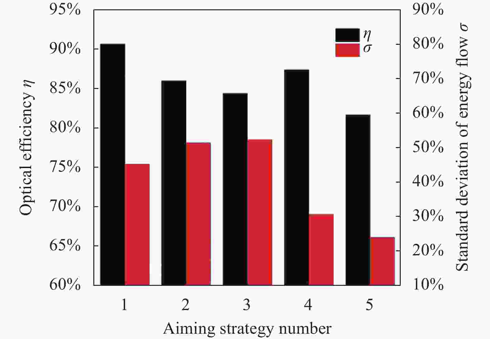
图 8 五种瞄准策略光学效率与能流标准差对比图
Figure 8. Comparison chart of optical efficiency and energy flow standard deviation for five aiming strategies
从图8中可以看出,所有反射镜瞄准点聚焦在集热管上(策略1),光学效率最高为90.7%,集热管表面辐射能流标准差为45.3%。策略2与策略3瞄准点聚集在集热管下部左右两侧,最外侧反射镜所反射的部分光线入射角大于CPC的最大接收半角45°,部分光线会溢出CPC开口造成光学效率下降,相较于策略1分别下降了4.7 %与6.2 %,同时能流标准差增大了6.2%与7.1%。策略4瞄准点均匀分布在−0.035~0.035 m之间,具有相对较高的光学效率87.4%,与策略1~3相比具有较低的能流标准差30.7% (相较于策略1降低了14.6%)。策略5与策略4相比虽然有更低的能流标准差24%,但光学效率相较于策略1下降了9%,是因为策略5的xaim最大已达0.07 m,由图5可知,xaim>0.04 m的瞄准点,光斑宽度大于CPC开口宽度400 mm,导致部分光线不能进入CPC开口,造成光学效率下降。
为进一步研究集热管表面能流分布,以集热管中心为轴,底部圆心角为0o,−180o~0o圆心角对应集热管左侧管周,0o~180o圆心角对应右侧管周,LCR随圆心角的变化如图9所示。
策略1~3均采用瞄准点集中的瞄准策略,策略1与策略2的瞄准点xaim分别为0.00 m与0.035 m,均小于集热管半径0.045 m,故反射光线大部分直接照射在集热管底部,只有较少部分光线掠过集热管后经CPC反射到达集热管顶部。策略3的瞄准点xaim为0.07 m,大于集热管半径0.045 m,则有较多光线未直接照射在集热管底部,而是经过CPC反射到达了集热管上部。从图9中可以看出,策略1与策略2在集热管底部有较高能流分布,在集热管顶部能流密度则很低。策略3在集热管上部有较高的能流分布,但LCR曲线整体波动较大。能流在管周60o的位置明显低于其他策略。策略4与策略5采用均匀化瞄准策略,整体LCR曲线平缓,能流分布均匀,且在集热管顶部LCR相较策略1高出了10.2与14。

图 9 五种瞄准策略局部聚光比对比图
Figure 9. Comparative diagram of local concentration ratio of five aiming strategies
-
综合考虑系统光学效率及能流辐射均匀性,选择瞄准策略1和4应用于线性菲涅耳集热实验系统空管预热,对照定性分析辐射能流的均匀性与集热管弯曲变形程度之间的关系,如图10所示。该实验系统总长度400 m,集热管设置多个温度测点。计算机控制系统进行温度、辐照强度等实时数据的采集。通过采用定占空比和变占空比两种模式进行空管预热。定占空比和变占空比模式中的参数选择根据参考文献[12]进行设置,其中定占空比预热扫描周期设定为40 s,聚焦时长设定为3 s。考虑到集热管安全以及便于观察,预热的上限温度设定为350 ℃ (实际预热温度不超过280 ℃)。现场集热管弯曲程度没有通用的考量标准,考虑到集热管之间还存在差异,集热管弯曲变形程度采用观察法,即当金属管贴近玻璃管时,认为已经达到弯曲极限,此时应立即停止加热,记录集热管温度及预热所需时间(表3)。

图 10 线性菲涅耳集热实验系统
Figure 10. Linear Fresnel heat collection experimental system
从表3中可以看出,无论是采用策略1还是策略4,变占空比控制温升曲线近乎直线,且在太阳辐照一定的条件下,预热速率更快,升温速率分别达到6.5 ℃/min和6 ℃/min,效果更佳。其次,在变占空比模式下升高相同温度,策略4下集热管弯曲变形程度远小于策略1。
表 3 集热管空管温度及预热实时温度
Table 3. Collector tube temperature and preheating real-time temperature
t/min T/℃ Constant duty cycle mode Variable duty cycle mode Strategy 1 Strategy 4 Strategy 1 Strategy 4 0 15 15 15 15 10 70 65 83 78 20 123 115 148 137 30 177 165 212 197 40 230 215 276 257 50 284 265 340 316 60 - 315 - = 70 - = - = 80 - = - = Note: “-” signifies that the temperature is not recorded as the evacuated tube reaches its bending limit and stops heating. “=” signifies that the evacuated tube did not reach its bending limit, but the temperature exceeded the preheating set value. As a result, the temperature is no longer recorded. The temperature represents an average of multiple evacuated tubes with an accuracy of ±1 °C. Recording began on April 15, 2023, at 10:00 A.M., with a 10-minute interval. DNI: 700-800 W/m2. -
提高光热转换效率和系统安全稳定运行是太阳能光热利用技术研究亘古不变的目标。线性菲涅耳式系统中,集热管表面能流密度非均匀分布,对系统运行、尤其是空管预热存在潜在的安全隐患。利用Tonatiuh软件构建了线性菲涅耳式聚光器,研究了不同瞄准策略下系统光学性能及能流分布的均匀性,得出以下结论:
1) 线性菲涅耳式聚光器采用瞄准点均匀分布的瞄准策略,聚光器在得到较高光学效率的同时能够提升集热管表面能流分布的均匀性;
2) 瞄准策略经过优化后,线性菲涅耳式聚光器光学效率可达到87.4%,集热管表面能流密度标准差显著下降15%,集热管顶部能流密度提升了10.2%;
3) 空管预热采用变占空比模式可实现恒温速升温,且采用策略4预热,集热管弯曲变形程度远小于策略1。
Optical performance of linear Fresnel condenser under different aiming strategies
-
摘要: 吸热管表面能流密度分布的均匀性对线性菲涅耳式聚光器的光热性能及安全运行有着重要影响。基于Tonatiuh光学仿真软件构建了线性菲涅耳式聚光器模型,研究了圆柱面形反射镜焦距及瞄准点位置与光斑宽度之间的关系,在此基础上探讨了不同瞄准策略下线性菲涅耳式聚光器的光学效率及能流分布的均匀性。结果表明:采用瞄准点均匀分布的瞄准策略,聚光器在保持较高光学效率的同时能够提升集热管表面能流分布的均匀性。采用优化后的瞄准策略,线性菲涅耳式聚光器光学效率可达到87.4%,集热管表面能流密度标准差由45.3%降低到30.7%,集热管顶部能流密度提升了10.2%。集热管空管预热采用该优化瞄准策略,在变占空比跟踪模式下,集热管弯曲变形程度远小于现有瞄准策略。该结果可为线性菲涅耳式聚光集热系统的优化设计提供理论支撑。Abstract:
Objective The linear Fresnel solar concentrator is one of the technologies of concentrator solar thermal power generation (CSP). Because the primary mirror are discrete flat mirrors and installed near the ground, the system has the advantages of strong wind resistance, which is especially suitable for large-scale construction in the northwest region of China with excellent solar energy resources but high wind speed. The existing research results show that the solar irradiation on the surface of the collector tube is very uneven in linear Fresnel concentrator system due to the different aiming strategies and the reflection profile of the secondary mirror. In addition, the medium in the tube is difficult to quickly divert the heat from the surface of the collector tube, the collector tube is easy to bend and deform, resulting in the breaking of the outer glass tube of the vacuum tube and the increasing heat loss of the system. The uniformity of heat flux density distribution on the absorber tube surface has a significant impact on the optical and thermal performance, as well as safe operation of linear Fresnel concentrating solar systems. Therefore, it is necessary to study the method for improving the uniform distribution of energy flux density to improve system efficiency and system security. Methods A linear Fresnel concentrator model was built using Tonatiuh optical simulation software, a cylindrical reflector was selected as the research object, and the relationship between the focal length (radius of the reflector) and the position of the aiming point on the aiming plane and the width of the spot was studied. Based on the fact that the width of the spot is not greater than the width of the secondary mirror opening, the focal length of the mirror and the distance from the center of the aiming point are determined. According to the different distribution of aiming points, five different aiming strategies are proposed, and the specific data are shown (Tab.2). Based on this, the optical efficiency and uniformity of heat flux distribution of the linear Fresnel concentrator under different aiming strategies were explored. Results and Discussions When the height difference between the edge and the bottom of the mirror is 2.85 mm, the spot width is the smallest (Fig.3), and it is far less than the aperture width of the secondary mirror opening. The aiming point is more than 0.04 mm off center, the spot width exceeds the aperture width of the secondary mirror (Fig.5). Using the aiming strategy of uniform distribution of aiming points, the concentrator will maintain high optical efficiency while improving the uniformity of energy flow distribution on the surface of the collector tube (Fig.7). With the optimized aiming strategy, the optical efficiency of the linear Fresnel concentrator can reach 87.4% (Fig.8), the standard deviation of energy flux density on the surface of the collector tube is reduced from 45.3% to 30.7% (Fig.8), and the energy flux density at the top of the collector tube is increased by 10.2% (Fig.9). Conclusions The uniformity of energy flux distribution on the surface of the collector tube of linear Fresnel concentrators can be improved by adopting different aiming strategies. By rationally distributing aiming points evenly on both sides of the center, the best spot uniformity on the surface of the collector tube and the best optical efficiency of the system can be achieved. When the aiming strategy is applied to the preheating of the empty pipe of the linear Fresnel concentrators, the bending deformation of the collector tube is much smaller than the existing aiming strategy under the variable duty ratio tracking mode. The research results can provide theoretical support for the optimal design of linear Fresnel concentrator heat collection system. -
图 3 反射镜焦距与光斑宽度关系图
Figure 3. Relationship between the focal length of the mirror and the width of the spot
图 6 Tonatiuh构建的线性菲涅耳式聚光系统
Figure 6. Linear Fresnel concentrating system built with Tonatiuh
图 7 五种瞄准策略集热管表面能流分布图
Figure 7. Surface energy flow distribution diagram of collector tubes with five aiming strategies
图 8 五种瞄准策略光学效率与能流标准差对比图
Figure 8. Comparison chart of optical efficiency and energy flow standard deviation for five aiming strategies
图 9 五种瞄准策略局部聚光比对比图
Figure 9. Comparative diagram of local concentration ratio of five aiming strategies
表 1 LFR系统参数
Table 1. Linear Fresnel system parameter
Parameter Value Width of the mirror, Wm/m 0.8 Length of the mirror, Lm/m 4 Number of mirrors, nm 16 Distance between adjacent mirrors, Sn/m 0.332 Height of receiver, H/m 9.056 Diameter of the tube/mm 90 Half acceptance angle of CPC, θc/(o) 45 Aperture width of CPC/mm 400  下载: 导出CSV
表 2 五种瞄准策略
Table 2. Five aiming strategy
Aiming
strategyxaim/m M1 M2 M3 M4 M5 M6 M7 M8 1 0.00 2 0.035 3 0.07 4 −0.035 −0.025 −0.015 −0.005 0.005 0.015 0.025 0.035 5 −0.07 −0.05 −0.03 −0.01 0.01 0.03 0.05 0.07
下载: 导出CSV
表 3 集热管空管温度及预热实时温度
Table 3. Collector tube temperature and preheating real-time temperature
t/min T/℃ Constant duty cycle mode Variable duty cycle mode Strategy 1 Strategy 4 Strategy 1 Strategy 4 0 15 15 15 15 10 70 65 83 78 20 123 115 148 137 30 177 165 212 197 40 230 215 276 257 50 284 265 340 316 60 - 315 - = 70 - = - = 80 - = - = Note: “-” signifies that the temperature is not recorded as the evacuated tube reaches its bending limit and stops heating. “=” signifies that the evacuated tube did not reach its bending limit, but the temperature exceeded the preheating set value. As a result, the temperature is no longer recorded. The temperature represents an average of multiple evacuated tubes with an accuracy of ±1 °C. Recording began on April 15, 2023, at 10:00 A.M., with a 10-minute interval. DNI: 700-800 W/m2.
下载: 导出CSV
-
[1] 姚玉璧, 郑绍忠, 杨扬, 等. 中国太阳能资源评估及其利用效率研究进展与展望[J]. 太阳能学报, 2022, 43(10): 524-535. Yao Yubi, Zhen Shaozhong, Yang Yang, et al. Progress and prospects on solar energy resoure evaluation and utilization efficiency in china [J]. Acta energiae solaris sinic, 2022, 43(10): 524-535. (in Chinese) [2] 谢聪, 王强. 中国新能源产业技术创新能力时空格局演变及影响因素分析[J]. 地理研究, 2022, 41(01): 130-148. Xie Cun, Wang Qiang. Spatio-temporal characteristics of new energy industry innovation capability and impact factors analysis in China [J]. Geographical Research, 2022, 41(1): 130-148. (in Chinese) [3] 张哲旸, 巨星, 潘信宇, 等. 太阳能光伏–光热复合发电技术及其商业化应用[J]. 发电技术, 2020(3): 220-230. Zhang Zheyang, Ju Xing, Pan Xingyu, et al. Photovoltaic/concentrated solar power hybrid technology and its commercial application [J]. Power Generation Technology, 2020, 41(3): 220-230. (in Chinese) [4] Islam M T, Huda N, Abdullah A B, et al. A comprehensive review of state-of-the-art concentrating solar power (CSP) technologies: Current status and research trends [J]. Renewable and Sustainable Energy Reviews, 2018, 91(4): 987-1018. doi: 10.1016/j.rser.2018.04.097 [5] Achkari O, El Fadar A. Latest developments on TES and CSP technologies–Energy and environmental issues, applications and research trends [J]. Applied Thermal Engineering, 2020, 167: 114806. doi: 10.1016/j.applthermaleng.2019.114806 [6] Fernández A G, Gomez-vidal J, Oró E, et al. Mainstreaming commercial CSP systems: A technology review [J]. Renewable Energy, 2019, 140(3): 152-176. doi: 10.1016/j.renene.2019.03.049 [7] 胡叶广, 张成, 周超英, 等. 太阳能光热发电的集热技术现状及前景分析[J]. 科学技术与工程, 2021, 21(09): 3421-3427. Hu Yeguang, Zhang Cheng, Zhou Chaoyong, et al. Current status and prospect analysis of heat collectiontechnology of solar thermal power [J]. Science Technology and Engineering, 2021, 21(9): 3421-3427. (in Chinese) [8] 孔令刚, 陈鑫龙, 张志勇, 等. 线性菲涅尔式光热发电技术现状及发展趋势[J]. 兰州交通大学学报, 2020, 39(06): 51-57. Kong Linggang, Chen Xinglong, Zhang Zhiyong, et al. Research status and development trend of linear fresnel concentrating solar power technology [J]. Journal of Lanzhou Jiaotong University, 2020, 39(6): 51-57. (in Chinese) [9] 王锐东, 马军, 王成龙, 等. 线性菲涅尔式聚光集热系统研究进展[J]. 红外与激光工程, 2021, 50(11): 246-264. doi: 10.3788/IRLA20210452 Wang Ruidong, Ma Jun, Wang Chenglong, et al. Progress of linear Fresnel concentrator heat collection system [J]. Infrared and Laser Engineering, 2021, 50(11): 20210452. (in Chinese) doi: 10.3788/IRLA20210452 [10] 大成科技(DCTC). 兰州大成敦煌50MW光热电站5月份发电成绩优异 [EB/OL]. [2023-07-03]. http://www.lzdctc.com/W/HdContentDisp-7-985-202163-537238.htm. [11] Bonk A, Sau S, Uranga N, et al. Advanced heat transfer fluids for direct molten salt line-focusing CSP plants [J]. Progress in Energy and Combustion Science, 2018, 67: 69-87. doi: 10.1016/j.pecs.2018.02.002 [12] 张志勇, 马军, 王成龙, 等. 线性菲涅尔系统空管预热模型分析及变占空比跟随控制应用研究[J]. 中国科学: 技术科学, 2021, 51: 315–323. Zhang Zhiyong, Ma Jun, Wang Chenglong, et al. Air tube preheating model of linear Fresnel systems and application of variable duty ratio following control [J]. Scientia Sinica Techologica, 2021, 51(3): 315-323. (in Chinese) [13] Häberle A, Zahler C, Lerchenmüller H, et al. The solarmundo line focussing fresnel collector. optical and thermal performance and cost calculations[C]//Proceedings of the 2002 SolarPACES International Symposium, 2002. [14] Moghimi M A, Craig K J, Meyer J P. A novel computational approach to combine the optical and thermal modelling of Linear Fresnel Collectors using the finite volume method [J]. Solar Energy, 2015, 116: 407-427. doi: 10.1016/j.solener.2015.04.014 [15] Eck M, Uhlig R, Mertins M, et al. Thermal load of direct steam-generating absorber tubes with large diameter in horizontal linear Fresnel collectors [J]. Heat Transfer Engineering, 2007, 28(1): 42-48. doi: 10.1080/01457630600985659 [16] Lu J, Yuan Q, Ding J, et al. Experimental studies on nonuniform heat transfer and deformation performances for trough solar receiver [J]. Applied Thermal Engineering, 2016, 109: 497-506. doi: 10.1016/j.applthermaleng.2016.08.096 [17] Qiu Y, Li M J, Wang K, et al. Aiming strategy optimization for uniform flux distribution in the receiver of a linear Fresnel solar reflector using a multi-objective genetic algorithm [J]. Applied Energy, 2017, 205: 1394-1407. doi: 10.1016/j.apenergy.2017.09.092 [18] 王成龙, 马军, 范多旺. 线性菲涅尔式聚光器的镜场布置与优化[J]. 光学精密工程, 2015, 23(1): 78-82. doi: 10.3788/OPE.20152301.0078 Wang Chenglong, Ma Jun, Fan Duowang. Arrangement and optimization of mirror field for linear Fresnel reflector system [J]. Optics and Precision Engineering, 2015, 23(1): 78-82. (in Chinese) doi: 10.3788/OPE.20152301.0078 [19] Welford W T, Winston R, Sinclair D C. The optics of nonimaging concentrators: Light and solar energy [J]. Physics Today, 1980, 33(6): 56-57. [20] 王成龙, 马军, 范多旺, 等. 用于线性菲涅尔式聚光系统的 CPC 仿真研究[J]. 红外与激光工程, 2015, 44(2): 556-560. doi: 10.3969/j.issn.1007-2276.2015.02.029 Wang Chenglong, Ma Jun, Fan Duowang, et al. Simulation study of a CPC for linear Fresnel reflector system [J]. Infrared and Laser Engineering, 2015, 44(2): 556-560. (in Chinese) doi: 10.3969/j.issn.1007-2276.2015.02.029 [21] Ma J, Wang C L, Zhou Y, et al. Optimized design of a linear fresnel collector with a compound parabolic secondary reflector [J]. Renewable Energy, 2021, 171(23): 141-148. doi: 10.1016/j.renene.2021.02.100 -

 点击查看大图

计量
- 文章访问数: 88
- HTML全文浏览量: 18
- PDF下载量: 21
- 被引次数: 0

