


-
红外辐射特性是高速飞行器红外探测、识别及跟踪的基础,目标的温度和辐射强度是识别、判断的关键性参数,它们集中反映了目标的物理特征[1]。高速飞行器飞行中段通常在大气层外,目标红外辐射远远大于空间背景的红外辐射,该阶段被认为是对高速飞行器进行防御的关键阶段[2]。高速飞行器飞行中段红外辐射主要与表面温度密切相关,而飞行器表面温度又与上升段气动加热、空间环境热辐射、防热材料结构等有关。多数分析者对无整流罩高速飞行器飞行中段的红外辐射特性研究主要考虑了太阳辐射、地球辐射和自身热辐射散热影响[3-8],而忽略了对飞行中段飞行器红外辐射影响较大的上升段气动加热影响因素,少数分析者虽然考虑了气动热的影响[9-10],但由于对气动热的预测精度不够或者采取假设气动加热后的平均温度分布,其研究结果也没有得到实测数据的验证,均造成了对无整流罩飞行器飞行中段表面温度预测偏差大,导致对飞行器红外辐射特性预测偏差大等问题。上述研究方法和结果还不能完全满足对无整流罩飞行器飞行中段红外辐射数据的需求。
文中针对无整流罩高速飞行器飞行中段红外辐射研究存在的问题,建立了包括飞行器上升段全流域气动加热、环境辐射加热、表面辐射散热和结构热传导等多种因素作用下的飞行器温度场和红外辐射的分析技术。应用发展的技术,计算分析了旋成体外形飞行器在阳光弹道条件下76º视角方向3~5 μm、8~12 μm波段光辐射强度随飞行时间的变化,重点研究了上升段气动加热对高速飞行器飞行中段红外辐射的影响。
-
图1为高速飞行器在飞行过程中与空间辐射能量交换的关系示意图,计算飞行器红外辐射不仅考虑了飞行器上升段的气动加热,飞行过程中表面向外的辐射散热,还考虑了空间环境太阳直接辐射加热和地球反射太阳辐射加热的影响。
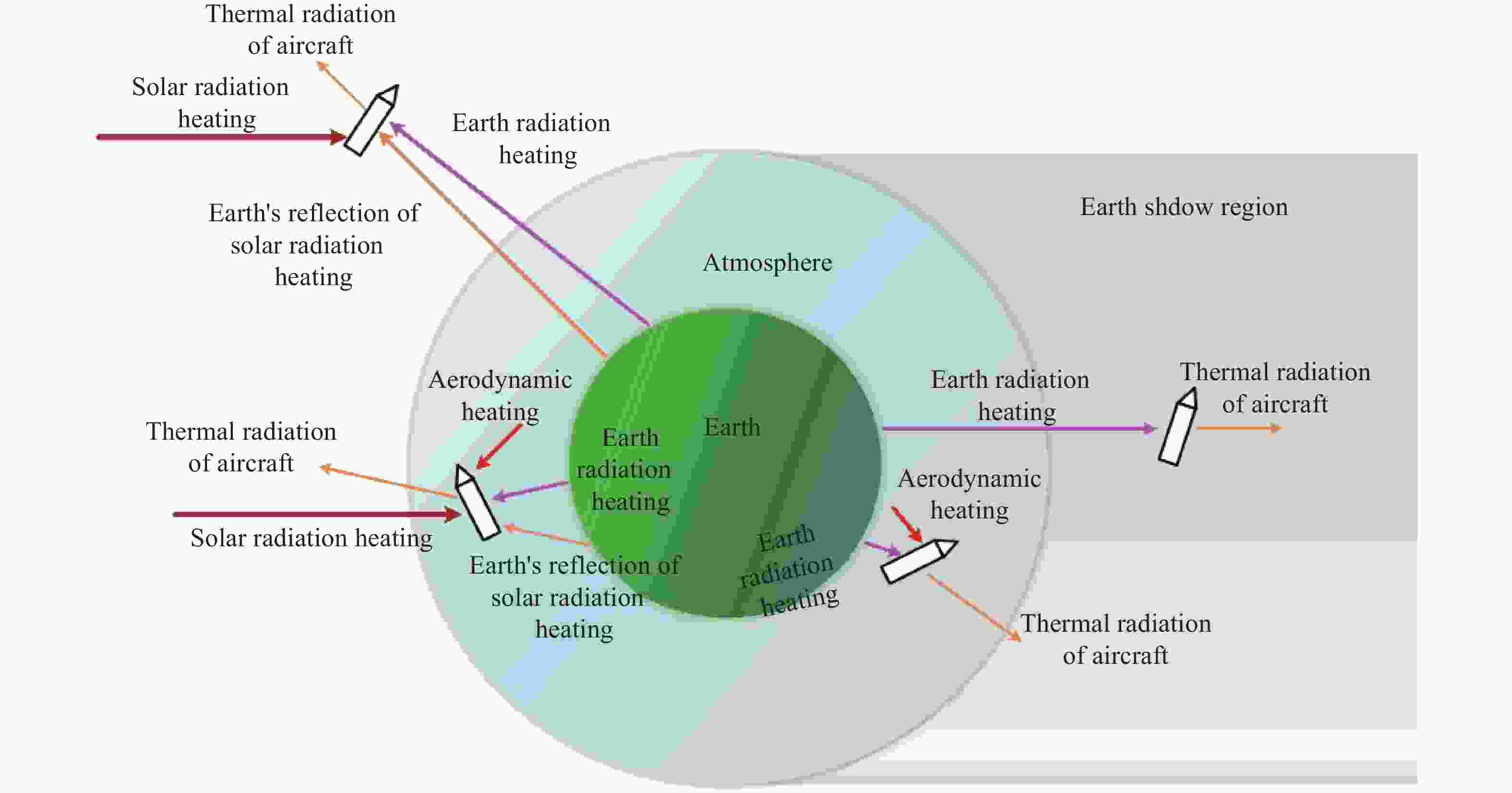
图 1 飞行器与空间环境的辐射能量交换
Figure 1. Radiation energy exchange between aircraft and space environment
-
为解决高速飞行器上升段气动热有效计算问题,选用了适于飞行器上升段气动热分析的亚/跨声速、高速下的连续流区气动热工程计算模型和转捩准则,适于稀薄过渡流区和自由分子流区气动热分析的气动热工程计算模型,实现了跨速域与跨流域气动热计算的结合,有效解决了飞行器红外辐射分析在上升段受到的气动加热影响分析手段的问题。
-
对于马赫数小于1.5的亚、跨声速飞行器气动热,采用热交换系数公式[11]:
$$ \left\{ \begin{gathered} {q_w} = {{\overline h}_x}({T_w} - {T_r}) \\ {{\overline h}_x} = \frac{{\displaystyle\int_0^L {{h_x}{\rm{d}}x} }}{L} \\ {h_x} = 0.029\;6{\rho _*}{C_{{p_*}}}{V_\infty }{({\rho _*}{V_\infty }x/{\mu _\infty })^{ - 1/5}}{Pr _*}^{ - 2/3} \\ {T_r} = {T_\infty }\left(1 + {r_T}\frac{{\gamma - 1}}{2}M_\infty ^2\right) \\ {r_T} = \sqrt[3]{{{{Pr }_*}}} \\ {T_*} = {T_\infty } + 0.5({T_w} - {T_\infty }) + 0.22({T_r} - {T_\infty }) \end{gathered} \right. $$ (1) 式中:$ {T_w} $为表面壁温,K;$ {T_r} $为恢复温度,K;$ {\overline h_x} $为平均对流换热系数,W/(m2·K)。
-
1) 连续流区物面气动热计算模型
连续流区气动热计算驻点采用Fay-Riddell公式[12],非驻点层流区热流采用修正Lees公式[13],湍流区热流采用平板参考焓法 [14],转捩区热流取当地层流热流和湍流热流的加权平均[15]。转捩准则采用局部马赫数相关的转捩准则[16]。
2) 稀薄过渡流区物面气动热模型
由于过渡流区流动物理现象的复杂性和控制方程的非线性,目前预测稀薄过渡流区气动热最广泛的方法为桥函数法或直接仿真DSMC方法。文中采用线性插值和调节参数进行校正的Linear桥函数连接连续流和自由分子流的热流[17]:
$$ \left\{ \begin{gathered} {q_{br}} = \alpha \frac{{({K_n}_{_{fm}} - {K_n}){q_c} + ({K_n} - {K_n}_{_c}){q_{fm}}}}{{{K_n}_{_{fm}} - {K_n}_{_c}}} \\ {K_n}_{_c} = 0.001 \\ {K_n}_{_{fm}} = 10 \\ \end{gathered} \right. $$ (2) 式中:$ {q_{br}} $为过渡流区的热流,W/m2;$ {q_c} $为连续流区的热流,W/m2;$ {q_{fm}} $为自由分子流区的热流,W/m2;$ {K_n} $为所在过渡区的Knudsen数;$ {K_n}_{_{fm}} $、$ {K_n}_{_c} $为流动分区的两个分界值,$ {K_n}_{_c} = 0.001 $,$ {K_n}_{_{fm}} = 10 $。
3) 自由分子流区物面气动热模型
自由分子流区空气稀薄,分子平均自由程远大于飞行器的特征长度,从飞行器壁面反射的空气分子要运动到距离壁面很远的地方才会与来流空气分子发生碰撞。自由分子流区飞行器表面热流通过求解基于 Maxwell 平衡气体分布假设无碰撞 Boltzmann 方程得到[18]:
$$ \left\{\begin{array}{l}{q}_{fm}=-\alpha \left\{\dfrac{\gamma +1}{2(\gamma -1)}nk{T}_{w}-\left[\left({S}^{2}+\dfrac{\gamma }{\gamma -1}\right)n-\phi \right]k{T}_{\infty }\right\}\\ n=\psi \left\{{{\rm{e}}}^{-{\eta }^{2}}+\eta \left[1+{\rm{erf}}(\eta )\right]\sqrt{\pi }\right\}\\ \psi =\dfrac{N{V}_{\infty }}{2S\sqrt{\pi }}\\ N=\dfrac{{p}_{\infty }}{k{T}_{\infty }}\begin{array}{cccc}& & & \begin{array}{cccc}\begin{array}{cccc}\begin{array}{cc}& \end{array}& & & \end{array}& & & \end{array}\end{array}\\ S=\dfrac{{V}_{\infty }}{\sqrt{2RT{}_{\infty }}}\\ \phi =\dfrac{\psi }{2}{{\rm{e}}}^{-{\eta }^{2}}\\ \eta =S\mathrm{cos}\theta \\ {\rm{erf}}(\eta )=\dfrac{2}{\sqrt{\pi }}{\displaystyle {\int }_{0}^{\eta }{{\rm{e}}}^{-{x}^{2}}{\rm{d}}x}\end{array}\right. $$ (3) 式中:α为调节系数;n为单位时间通过单位面积的分子数,个/(m2·s);k为玻耳兹曼常数,1.38066×10−23 J/K;N为单位体积内的分子数,个/m3;$ R $为气体常数,J/(kg·K);$ {p_\infty } $为来流压力,Pa;$ {V_\infty } $为来流速度,m/s;$ {T_\infty } $为来流温度,K;${\rm{erf}}(\eta )$为误差函数;$ \theta $为物面法线与来流速度的夹角,(°)。
-
对于飞行中段高速飞行器,其周围为真空状态,气动加热量较小,基本可以不考虑,主要考虑飞行器自身以热辐射形式向外的辐射能量和接收太阳、地球的环境辐射热量。对于上述几种辐射加热环境,分别采用不同公式予以计算。
-
在飞行中段,受到阳光照射的飞行器表面会吸收太阳的辐射能。在太阳光束平行、均匀的假设条件下,飞行器微元表面吸收的太阳直接辐射能$ {q_{sun}} $为[19]:
$$ {q_{sun}} = {\alpha _s}{I_s}{A_{pro}} $$ (4) 式中:$ {\alpha _s} $为飞行器表面的太阳辐射吸收率;$ {A_{pro}} $为单位微元表面在垂直于太阳光方向上的投影面积,m2;$ {I_s} $为太阳直接辐射照度,W/m2。
-
地球会把吸收的太阳辐射能以红外热辐射的方式向空间辐射,在地球表面各处的辐射强度相等的条件下,飞行器微元表面吸收的地球红外辐射能$ {q_{earth}} $为[19]:
$$ {q_{earth}} = {\alpha _{IR}}{I_{earth}}{\varphi _{2\;{\rm{mm}}}} $$ (5) 式中:$ {\alpha _{IR}} $为飞行器外表面的红外吸收率;$ {I_{earth}} $为地球自身红外辐射密度,$ {I_{earth}} = 220 $ W/m2;${\varphi _{2 \;{\rm{mm}}}}$为地球红外辐射的角系数。
-
在假定地球对太阳辐射的反射为漫反射和各处均匀的条件下,并遵循Lambert定律,飞行器微元表面吸收的地球反射太阳辐射能$ {q_{ref}} $[19]为:
$$ \left\{ \begin{gathered} {q_{ref}} = {\alpha _s}{\alpha _r}{I_s}{\varphi _{3\;{\rm{mm}}}} \\ {\varphi _{3\;{\rm{mm}}}} = {\varphi _{2\;{\rm{mm}}}}\cos \varPhi \\ \end{gathered} \right. $$ (6) 式中:$ {\alpha _r} $为球表面对太阳辐射的平均反射率;$ {\varphi _{3 \;{\rm{mm}}}} $为地球反照角系数;$ \varPhi $为地球反照角,rad。
-
综合考虑飞行器上升段气动加热、环境辐射加热、自身热辐射等对飞行器温度和红外辐射的影响基础上,采用瞬态一维多层结构的热传导模型满足实时快速分析,该模型未考虑层结构之间的接触热阻。
1) 瞬态一维多层结构热传导模型
飞行器防热材料层、隔热层、承力结构层的一维热传导方程分别如下。
① 防热层一维热传导方程[20]
$$ {\rho _s}{C_s}\frac{{\partial T}}{{\partial t}} = \frac{\partial }{{\partial y}}\left( {{k_s}\frac{{\partial T}}{{\partial y}}} \right) $$ (7) 初值条件为:$ T\left( {y,0} \right) = const $;
边界条件为:$ {\dot Q_N} - \varepsilon \sigma T_w^4 = - {\left( {{k_s}\partial T/\partial y} \right)_w} $。
式中:$ \;{\rho _s} $为防热层材料密度,kg/m3;$ {C_s} $为防热层材料比热,J/(kg·K);$ {k_s} $为热传导系数,W/(m·K);$ T $为温度,K;$ t $为时间,s;$ y $为传热厚度,m;$ {\dot Q_N} $为传入防热层内部的热流,W/m2;$ \varepsilon $为辐射系数;$ \sigma $为斯蒂芬-玻耳兹曼常数。
② 隔热层一维热传导方程
$$ {\rho '_s}{C'_s}\frac{{\partial T'}}{{\partial t}} = \frac{\partial }{{\partial y}}\left( {{{k'}_s}\frac{{\partial T'}}{{\partial y}}} \right) $$ (8) 防热材料与隔热材料交界面$ y=x_{0} $处,满足温度相等的边界条件:
$$ T = T' $$ (9) ③ 承力结构层一维热传导方程
$$ {\rho ''_s}{C''_s}\frac{{\partial T''}}{{\partial t}} = \frac{\partial }{{\partial y}}\left( {{{k''}_s}\frac{{\partial T''}}{{\partial y}}} \right) $$ (10) 隔热材料与承力结构交界面$ y = {x_0} + {x_1} $处,满足温度相等的边界条件:
$$ T^{\prime}=T^{\prime \prime} $$ (11) 整个防热层内表面$ y = {x_0} + {x_1} + {x_2} $处的边界条件是已知温度:
$$ T'' = {T_b} $$ (12) 2) 飞行器红外辐射强度观测计算方法
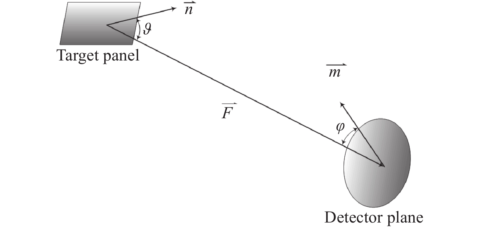
设飞行器表面微元$ {\rm{d}} A $法线方向为$ \vec{n}$,面元$ {\rm{d}} A $在波长$ \lambda $~$\lambda+{\rm{d}} \lambda $范围辐射到在方位角$ \varphi $与表面法线夹角为$ \vartheta $方向上的辐射强度为(图2)[21]:
$$ {\rm{d}}{I_\lambda } = \varepsilon \cdot {L_\lambda }\cos \vartheta \cos \varphi {\rm{d}}A{\rm{d}}\lambda $$ (13) 对公式(13)积分可以得到某观测视角方向上某个波段的飞行器光辐射强度,其中$ {L_\lambda } $为光谱辐射亮度。

图 2 目标表面与探测器瞳面的几何位置关系
Figure 2. Geometric position relationship between target surface and pupil surface of detector
-
飞行中段高速飞行器的红外辐射主要是本体的辐射,而本体的辐射与飞行器的表面温度紧密相关,文中按照文献[19]给出的某飞行器外形(图3)、飞行试验条件和测温探测器结构,计算了测点1 (与头部距离为1500 mm)、测点2 (与头部距离为2 000 mm) 阳光照射表面下1 mm处的温度变化历程(图4),蓝色三角符号线为飞行试验测量值,红色实线为计算值),温度历程包括在大气层内飞行时的升温阶段和在大气层外的降温阶段,测点随飞行时间的计算温度与飞行试验测量温度符合较好,变化规律与飞行试验测量结果一致,飞行中段温度相对偏差在±4%内(图5)。

图 4 飞行试验测点位置计算温度与测量温度对比
Figure 4. Comparison between the calculated temperature and the measured temperature of the flight test measuring point position
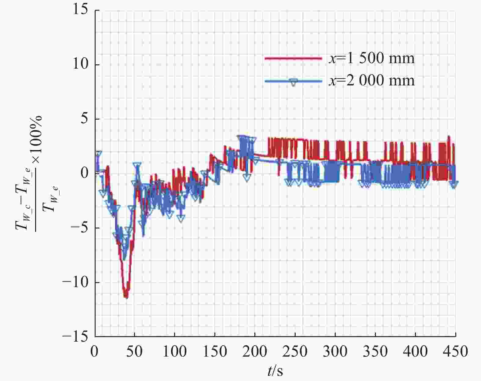
图 5 飞行试验测点位置计算温度与测量温度对比相对偏差
Figure 5. Relative deviation of comparison between calculated temperature and measured temperature of flight test measuring point position
-
假定飞行器几何外形参数如图6所示,飞行器头部全部为碳-碳纤维防热材料($ x \leqslant {R_n} $);身部外层为碳酚醛复合材料,厚度6 mm;中间层为隔热材料,厚度3 mm;内部为承力结构LF6材料,厚度2 mm,以上材料的物性参数见表1。

图 6 假定飞行器几何外形(单位:mm)
Figure 6. Assumes the geometric shape of aircraft (Unit: mm)
表 1 飞行器材料物性参数
Table 1. Physical parameters of aircraft
Material Density/
kg·m–3Specific/
J·(kg·K)–1Thermal conductivity/
W·(m·K)–1Carbon-carbon composites 1750 1172.3 0.83736 Carbon-phenolic composites 1400 1256 0.7536 Insulating material 220 550 0.019 LF6 2640 921 125.6 飞行器发射初温取288 K、表面红外发射率0.85、飞行器对太阳辐射的吸收系数取0.4 (主要是紫外可见光辐射)、飞行器对地球辐射的吸收系数取0.8 (主要是长波红外辐射);计算阳光弹道下的飞行器红外辐射分布特性及时间变化特性,红外波段3~5 μm、8~12 μm,观测视角76°。
图7所示为飞行器沿假定弹道飞行时,在飞行器的上升段受强的气动加热影响,测点温度迅速上升,在飞行到第50.6 s时,驻点温度达到最大值655.743 K。在第48.9~77.8 s飞行期间,由于飞行器速度持续减小,气动加热小于飞行器表面向外的辐射散热,表面温度出现快速下降。第77.8 s后飞行器飞行高度增加,速度也增加,在飞行到第108 s时,飞行速度达到最大值,在此飞行期间,飞行速度的增加使飞行器局部气动热大于向外表的热辐射,导致飞行器表面在第94.8 s出现第二个小峰值。在第94.8~108 s 飞行期间,空气越来越稀薄,气动加热小于向飞行器表面向外的辐射热和向内的传导热,飞行器表面温度继续快速下降。飞出大气层后,没有气动加热作用,而飞行器会继续向外辐射热量和向内传导热量,初期由于飞行器表面温度高,向外辐射散热和向内传导热量大,温度下降非常快,温度降低后,辐射散热量变小,还有太阳辐射和地球辐射与地球反射太阳辐射照射,表面温度降低幅度不大,在整个飞行中段,其温度均高于发射初温。
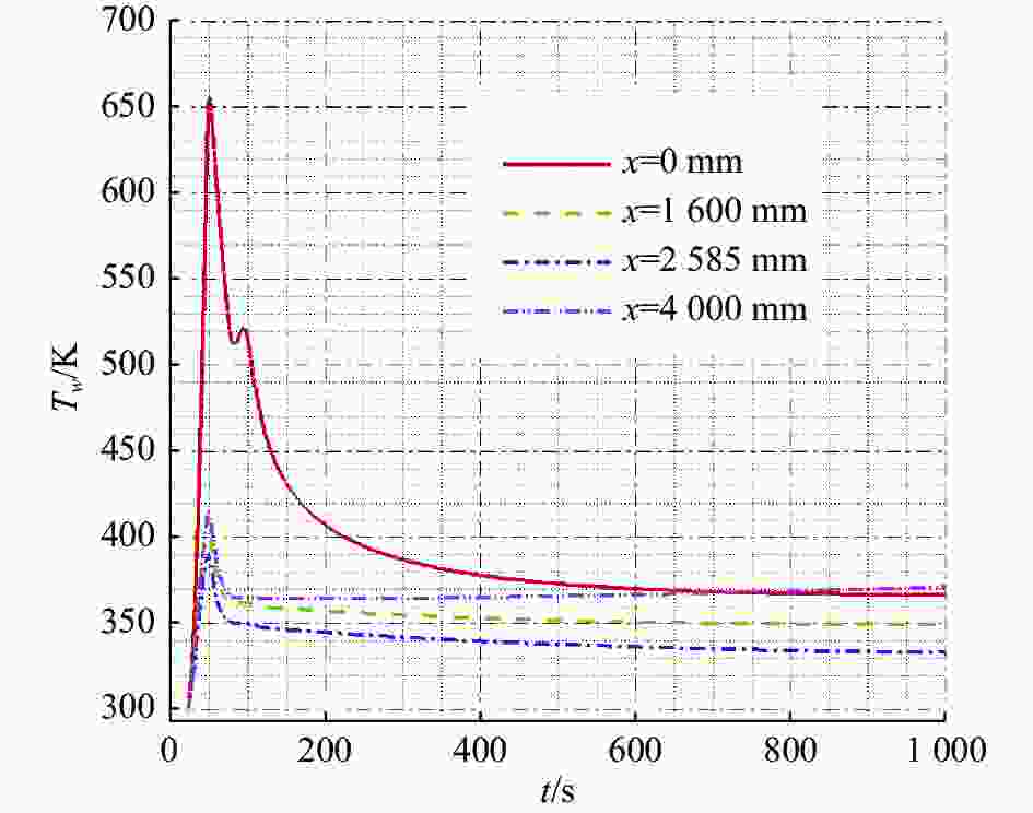
图 7 考虑气动加热和阳光照射时典型位置温度随飞行时间变化
Figure 7. Variation temperature of the typical position with time of flight under aerodynamic heating and sunlight
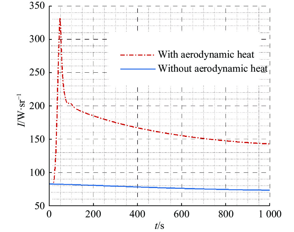
图8所示为不考虑气动加热,只考虑空间热辐射加热时飞行器典型位置温度随飞行时间的变化历程,温度逐渐上升,最高温度只比初温上升了16.5 K。由于假定阳光从飞行器上部垂直于x轴照射,飞行器物面角为0°的阳光照射面温度最高。图9和图10分别为3~5 μm波段8~12 μm波段,考虑气动加热和不考虑气动加热情况下飞行器光辐射强度计算结果的比较。可以看出,在上升初始阶段,飞行器主要受强的气动加热影响,其表面温度迅速上升,飞行器红外辐射强度也迅速上升;随着飞行高度增加,空气越稀薄,当气动加热远小于飞行器表面向外的辐射热和向内的传导热之和时,表面温度快速下降(图7),辐射强度也快速下降(图9、图10);飞出大气层进入飞行中段后,没有气动加热作用,而飞行器会继续向外辐射热和向内传导热量,初期由于飞行器表面温度高,辐射散热和向内传导热量大,温度下降非常快,红外辐射强度也下降得很快;此后,由于表面温度降低幅度不大,其红外辐射强度降低幅度也不大。图中可以看出,上升段未考虑气动加热时,飞行器飞行中段辐射强度变化不明显,且辐射强度量值也比考虑气动加热时小很多(图9、图10)。

图 8 不考虑气动加热,只考虑阳光照射时典型位置温度随飞行时间变化
Figure 8. Variation temperature of the typical position with time of flight under sunlight without considering aerodynamic heating

图 9 3~5 μm波段光辐射强度随飞行时间的变化
Figure 9. The radiation intensity of 3-5 μm band changes with flight time

图 10 8~12 μm波段光辐射强度随飞行时间的变化
Figure 10. The radiation intensity of 8-12 μm band changes with time of flight
图11为3~5 μm和8~12 μm波段飞行器光辐射强度随飞行时间的变化比较,8~12 μm波段飞行器光辐射强度比3~5 μm波段强很多,8~12 μm波段作为飞行中段预警探测波段效果更佳。

图 11 3~5 μm和8~12 μm波段光辐射强度随飞行时间变化比较
Figure 11. Comparison of the variation of radiation intensity at 3-5 μm and 8-12 μm bands with time of flight
-
文中以飞行中段高速飞行器红外辐射建模仿真为目的,发展了考虑飞行器上升段全流域气动加热等因素影响的高速飞行器飞行中段温度场和红外辐射特性分析技术,解决了高速飞行器上升段跨速域与跨流域的气动热分析建模、飞行器在多种热源加热和辐射散热及复杂结构传热耦合作用下的飞行器温度场和红外辐射分析建模等问题,该技术计算分析数据可靠,温度分析结果与飞行试验测量数据一致。通过对飞行中段假定旋成体外形飞行器光辐射特性计算分析发现,上升段的气动加热会对飞行器飞行中段的红外辐射产生较大影响;在飞行中段,飞行器在长波8~12 μm波段的红外辐射强度明显大于在中波3~5 μm波段的红外辐射强度。因此,采用8~12 μm波段作为对飞行中段高速飞行器的探测波段有利于增大探测距离。
Analysis of the influence of aerodynamic heating in ascent stage on infrared radiation characteristics of high-speed aircraft in midcourse
-
摘要: 飞行中段高速飞行器红外辐射特性是对其进行红外探测、识别及跟踪的基础。飞行中段高速飞行器红外辐射与表面温度密切相关,而飞行器表面温度又与上升段气动加热、空间环境热辐射、防热材料结构等有关,特别是上升段气动加热对飞行中段飞行器红外辐射的影响不容忽视。为获得复杂环境背景下高速飞行器在飞行中段的红外辐射,综合考虑上升段气动加热、环境辐射加热、表面辐射散热和结构热传导等主要因素影响,采用气动热工程计算模型、空间辐射加热、一维多层热传导计算方法,建立了高速飞行器红外辐射分析技术,实现了气动加热、环境辐射加热、自身辐射散热、结构热传导等多种主要因素影响下的高速飞行器飞行中段温度场和红外辐射分析。结果表明:上升段的气动加热会对飞行中段的高速飞行器红外辐射产生较大影响;在飞行中段,飞行器在长波8~12 μm波段的红外辐射强度明显大于在中波3~5 μm波段的红外辐射强度,选择8~12 μm波段更有利于对飞行中段高速飞行器的探测。Abstract:
Objective Infrared radiation characteristics is the basis of midcourse infrared warning, detection, identification and track of high-speed aircraft. High-speed aircraft midcourse infrared radiation is closely related to surface temperature, which is related to ascent-stage aero-heating, space thermal radiation, heat-shield structure, and so on. In order to obtain high-speed aircraft’s midcourse infrared radiation in the complex environment background, it is necessary to study the influence of aero-heating, space thermal radiation, surface heat-shield radiating and structure heat conduction on the infrared radiation. Methods Taking into account the influence of ascent-stage aero-heating, space thermal radiation, surface heat-shield radiating and structure heat conduction, making use of aerodynamic heating engineering computation model, space thermal heating computation model, and 1D multi-layer heat conduction computation method, the high-speed aircraft infrared radiation analysis technology is established, and high-speed aircraft midcourse temperature field and infrared radiation analysis is realized under the influence of aero-heating, space radiation heating, radiation heat dissipation, structure heat conduction, and so on. Results and Discussions The computation temperature results match well with flight test results under typical working conditions (Fig.4-5), which verifies the validity of the computation model and methods. The ascent-stage aero-heating has a large effect on the midcourse surface temperature and infrared radiation (Fig.7-10). In the midcourse, the infrared radiation intensity in the wavelength range of 8-12 μm is notably larger than that of 3-5 μm. Therefore, choosing the wavelength range of 8-12 μm is more advantageous for high-speed aircraft midcourse detection (Fig.11). Conclusions In order to simulate the infrared radiation of the high-speed aircraft in midcourse flight, the temperature field and infrared radiation characteristics analysis technology is developed, considering the influence of ascent-stage aero-heating and so on. The technology is validated through comparison with flight test measurements. It is found that: the ascent-stage aero-heating has a large effect on the midcourse infrared radiation. In the midcourse, the infrared radiation intensity in the wavelength range of 8-12 μm is notably larger than that of 3-5 μm. Therefore, choosing the wavelength range of 8-12 μm is more advantageous for high-speed aircraft midcourse detection. -
Key words:
- high-speed aircraft /
- midcourse flight /
- temperature /
- infrared radiation
-
图 1 飞行器与空间环境的辐射能量交换
Figure 1. Radiation energy exchange between aircraft and space environment
图 2 目标表面与探测器瞳面的几何位置关系
Figure 2. Geometric position relationship between target surface and pupil surface of detector
图 4 飞行试验测点位置计算温度与测量温度对比
Figure 4. Comparison between the calculated temperature and the measured temperature of the flight test measuring point position
图 5 飞行试验测点位置计算温度与测量温度对比相对偏差
Figure 5. Relative deviation of comparison between calculated temperature and measured temperature of flight test measuring point position
图 7 考虑气动加热和阳光照射时典型位置温度随飞行时间变化
Figure 7. Variation temperature of the typical position with time of flight under aerodynamic heating and sunlight
图 8 不考虑气动加热,只考虑阳光照射时典型位置温度随飞行时间变化
Figure 8. Variation temperature of the typical position with time of flight under sunlight without considering aerodynamic heating
图 9 3~5 μm波段光辐射强度随飞行时间的变化
Figure 9. The radiation intensity of 3-5 μm band changes with flight time
图 10 8~12 μm波段光辐射强度随飞行时间的变化
Figure 10. The radiation intensity of 8-12 μm band changes with time of flight
图 11 3~5 μm和8~12 μm波段光辐射强度随飞行时间变化比较
Figure 11. Comparison of the variation of radiation intensity at 3-5 μm and 8-12 μm bands with time of flight
表 1 飞行器材料物性参数
Table 1. Physical parameters of aircraft
Material Density/
kg·m–3Specific/
J·(kg·K)–1Thermal conductivity/
W·(m·K)–1Carbon-carbon composites 1750 1172.3 0.83736 Carbon-phenolic composites 1400 1256 0.7536 Insulating material 220 550 0.019 LF6 2640 921 125.6  下载: 导出CSV
-
[1] Snigirev A, Snigireva I, Kohn V, et al. On the possibilities of X-ray phase contrast micro-imaging by coherent high-energy synchrotron radiation [J]. Rev Sci Instrum, 1995, 66(12): 5486-5492. [2] Fetter S, Sessler A M, Cornwall M, et al. Countermeasures: A technical evaluation of the operational effectiveness of the planned US national missile defense system [EB/OL]. [2023-10-13]. https://drum.lib.umd.edu/handle/1903/4333. [3] Degges T G, Smith H J P. A high altitude infrared radiance model[R]. AFGL-TR-77-0271, 1977. [4] Liu Tao, Jiang Weidong, Li Xiang, et al. Simulation calculation of synamic infrared radiation characteristics of the target in ballistic midcourse [J]. Infrared and Laser Engineering, 2008, 37(6): 955-958. (in Chinese) [5] Wilkins S W, Gureyev T E, Gao D, et al. Phase-contrast imaging using polychromatic hard X-rays [J]. Nature, 1996, 384(28): 335-338. [6] Zhang Jun, Yang Hua, Ling Yongshun, et al. Theoretical analysis of temperature field on the surface of ballistic missile warhead in midcourse [J]. Infrared and Laser Engineering, 2005, 34(5): 582-586. (in Chinese) [7] She Eryong, Ma Hongmei, Ding Yuzheng, et al. Design of midcourse surveillance and tracking simulation system for ballistic missile [J]. Aerospace Control, 2007, 25(2): 68-72. (in Chinese) [8] Hu Wei, Yang Jianjun, Wang Sen, et al. TBM′s midcourse infrared radiation traits modeling and simulation [J]. Optoelectronic Technology, 2009, 29(4): 240-243. (in Chinese) [9] Chen Naiguang. Temperature changing rule of ballistic missile [J]. Aerospace Electronic Warfare, 2007, 23(4): 5-8. (in Chinese) [10] Lu Xiaofei, Sheng Jie. Review of surface temperature of ballistic missile in flight [J]. Infrared, 2015, 37(1): 1-6. (in Chinese) [11] Wang Zhen. Research on the thermal-control method for aircraft wings and thermal performance analysis of the heat pipe [D]. Nanjing: Nanjing University of Aeronautics and Astronautics, 2009. (in Chinese) [12] Fay J A, Riddell F R. Theory of stagnation point heat transfer in dissociated air [J]. J Aero Sci, 1958, 25(2): 73-85. [13] Lees L. Laminar heat transfer over blunt nosed bodies at hypersonic flight speed [J]. Jet Propulsion, 1956, 26(4): 259-269. doi: 10.2514/8.6977 [14] Zhang Z C. Hypersonic Aerothermodynamic and Thermal Protection[M]. Beijing: National Defence Industry Press, 2003: 84-85. (in Chinese) [15] Chen K K. Three dimensional nosetip shape changes in hypersonic flow. Part 1: Illustration of a mathe- matical model-characteristic method[R]. AIAA-73- 0762, 1973. [16] Baker R L. Low temperature ablator nosetip shape change at angle of attack[R]. AIAA-72-90, 1972. [17] Rong Yisheng, Liu Weiqiang. Reseach on accommodation parameter of linear bridging relation for blunt cone in transitional regime [J]. Acta Physica Sinica, 2012, 61(4): 040508. (in Chinese) doi: 10.7498/aps.61.040508 [18] Engel C D, Praharaj S C. Miniver upgrade for the avid system. Volume 1: Lanmin user′s manual[R]. NASA CR-172212,1983. [19] Shi Anhua, Shi Weibo, Sun Haihao, et al. The effect of detector installing structure on wall temperature measurement of vehicle [J]. Journal of Experiments in Fluid Mechanics, 2016, 30(4): 32-36. (in Chinese) [20] Guo Yijun. Analysis of ablative thermal response of charring material with engineering applications [J]. Acta Aerodynamica Sinica, 1994, 12(1): 94-99. (in Chinese) [21] Shi Weibo, Sun Haihao, Yu Zhefeng, et al. The analysis of infrared radiation characteristics for HTV-2-like hypersonic gliding vehicle body [J]. Infrared, 2022, 43(1): 26-34. (in Chinese) -

 点击查看大图

计量
- 文章访问数: 92
- HTML全文浏览量: 14
- PDF下载量: 34
- 被引次数: 0

