


-
碳化硅(SiC)反射镜是空间光学系统的主要元件。随着人们对卫星成像质量要求越来越高,其光学系统主反射镜的口径也越来越大。而大口径的反射镜意味着系统质量和发射成本的增加,因此,大口径反射镜必须采用轻量化结构设计[1-3]。
为提高加工效率,主反射镜在抛光之前需要先经过粗加工去除镜胚烧结铸造时的表面余量,但反射镜的超薄轻量化设计使粗加工变得十分困难。一方面超薄的镜面使镜面本身脆性增加,在加工过程中容易使镜子表面受应力过大而破裂;另一方面,反射镜背部轻量化孔的设计会使反射镜本身刚度降低,自身固有频率降低,导致反射镜在铣磨过程中容易与加工系统发生共振,使镜子被破坏。目前普遍采用人工研磨或者超声振动铣磨的方法进行粗加工,但这两种加工方法表面去除效率较低,加工周期长,无法满足空间光学系统对研制周期的需求。
国内外对碳化硅反射镜表面去除已有研究,陈曦[4]等人采用五轴联动范成法铣磨,对Ф100 mm离轴抛物镜进行铣磨,经过一次加工使面形精度PV达到7 μm。于建海[5]等人建立了母线误差曲线的补偿模型,对磨削误差进行实时补偿,并采用五轴加工中心对Ф1.6 m口径同轴非球面反射镜进行磨削,最终使反射镜面形精度PV达到27.4 μm。Chanda[6]等人运用高阶多尺度法(MMS),通过对车削过程刀具的非线性动力学进行分析,建立了非线性刚度模型,并给出了系统无颤振车削加工的条件,为稳定车削加工提供了参考。Zhang[7]等人利用有限元分析,分析了超声振动磨削SiC复合材料的去除机理,给出了纤维损伤的类型,为超声振动去除提供了重要指导。上述文献中并未对大口径的超轻量化反射镜的铣磨进行研究讨论。
为解决大口径超轻量化反射镜加工难、效率低的问题,通过对反射镜加工过程中产生共振的机理进行分析,提出了一种超精密高效五轴铣磨加工方法。利用环形工装支撑反射镜边缘,提高系统的固有频率,采用平行进给的给刀方式获得更高的表面去除效率,建立了反射镜仿真模型,进行了铣磨应力和系统模态的计算分析,并最终对Ф510 mm的大口径超轻量化碳化硅反射镜表面进行快速铣磨。对加工后的反射镜进行检测,结果表明,反射镜面形精度已达到进一步抛光的要求,验证了该加工方法的可行性,解决了大口径轻量化反射镜加工难、周期长的问题。
-
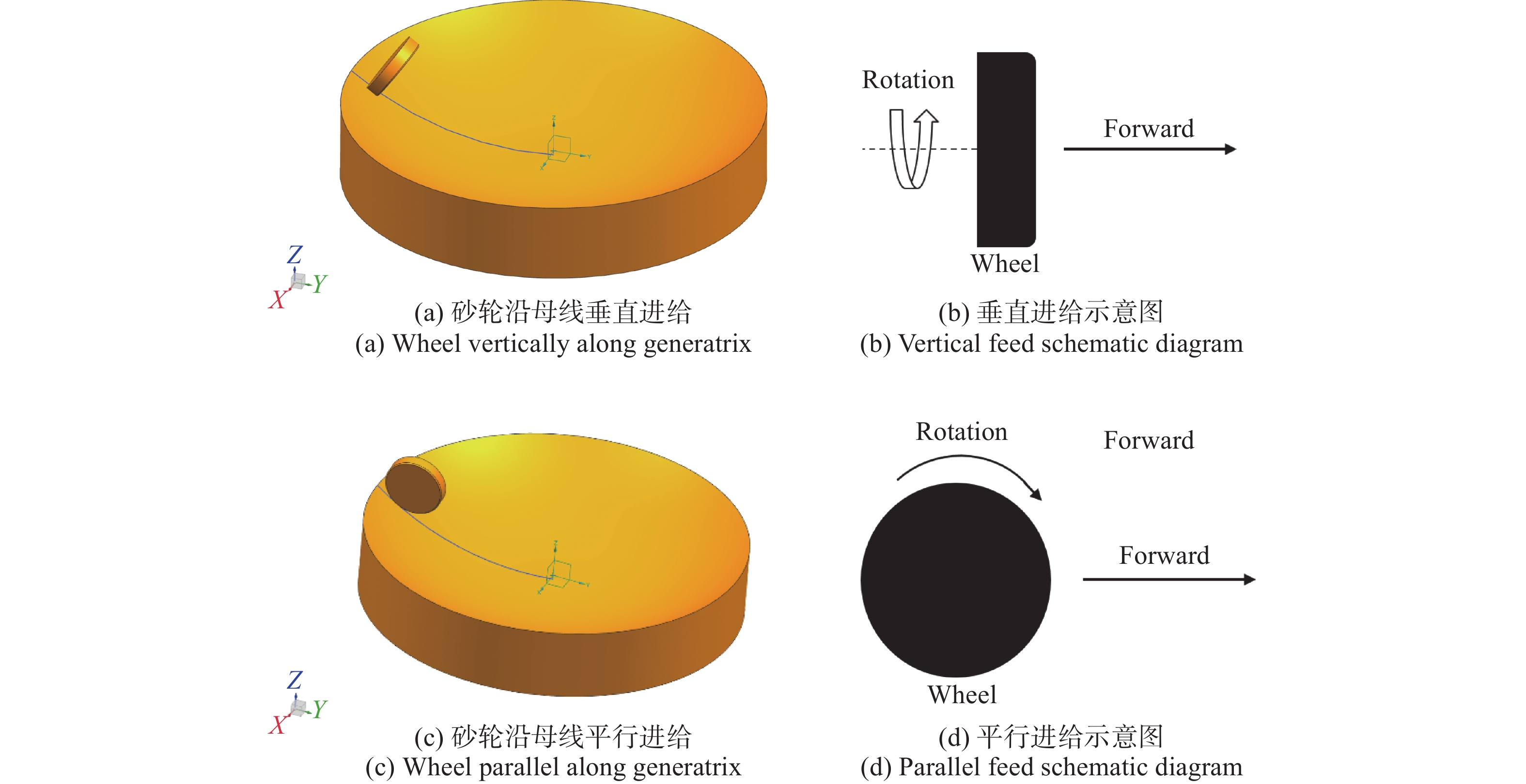
铣磨加工[8]具有刀具转速高、加工精度高、材料去除率高等优点,分为铣削和磨削。铣削采用的刀具为切削刀,主要适用于加工深槽。而磨削采用的刀具为圆盘形的砂轮,主要用于从工件上去除材料以及抛光工件。反射镜铣磨方法根据铣磨砂轮主轴与反射镜回转轴的相对运动关系,可以分为平行铣磨法、横向铣磨法和斜轴铣磨法等。由于砂轮直径的限制,对于非球面的加工一般采用斜轴铣磨法。斜轴铣磨法的铣磨砂轮有两种进给方式,一种是砂轮的旋转面与进给方向垂直的垂直进给方式,另一种是砂轮的旋转面与进给方向共面的平行进给方式,如图1所示,两种方式都为砂轮沿着反射镜母线缓慢进给。

图 1 斜轴铣磨原理图
Figure 1. Schematic diagram of oblique axis milling
张志宇[9]等人对于两种不同加工方式的加工表面理论残留高度进行了分析,并给出了计算公式。
对于垂直进给方式,表面理论残留高度$ {d_p} $的计算方法为:
$$ {d_p} = f\sin \alpha \cos \alpha $$ (1) 式中:$ f $为砂轮的进给量;$ \alpha $为砂轮轴与铣磨点法线方向的夹角。对于平行进给方式,表面理论残留高度$ {d_c} $的计算方法为:
$$ {d_c} = \frac{{{f^2}}}{{8{R_w}}} $$ (2) 式中:$ f $为砂轮的进给量;$ {R_w} $为砂轮的半径。
在实际加工过程中,由于砂轮的直径$ {R_w} $要超出砂轮进给量$ f $三个数量级甚至更多,采用铣磨方向与进给方向平行的方式可以获得更少的表面残留,节约加工时间和成本。文中采用平行进给方式进行定角度加工,加工刀具轨迹如图2所示,铣磨砂轮在工件表面沿着螺旋线加工,通过初始切削点的不断变化,最终使螺旋线的运动轨迹能够扫掠反射镜全表面。

图 2 刀具运动轨迹图
Figure 2. Tool motion trajectory diagram
-
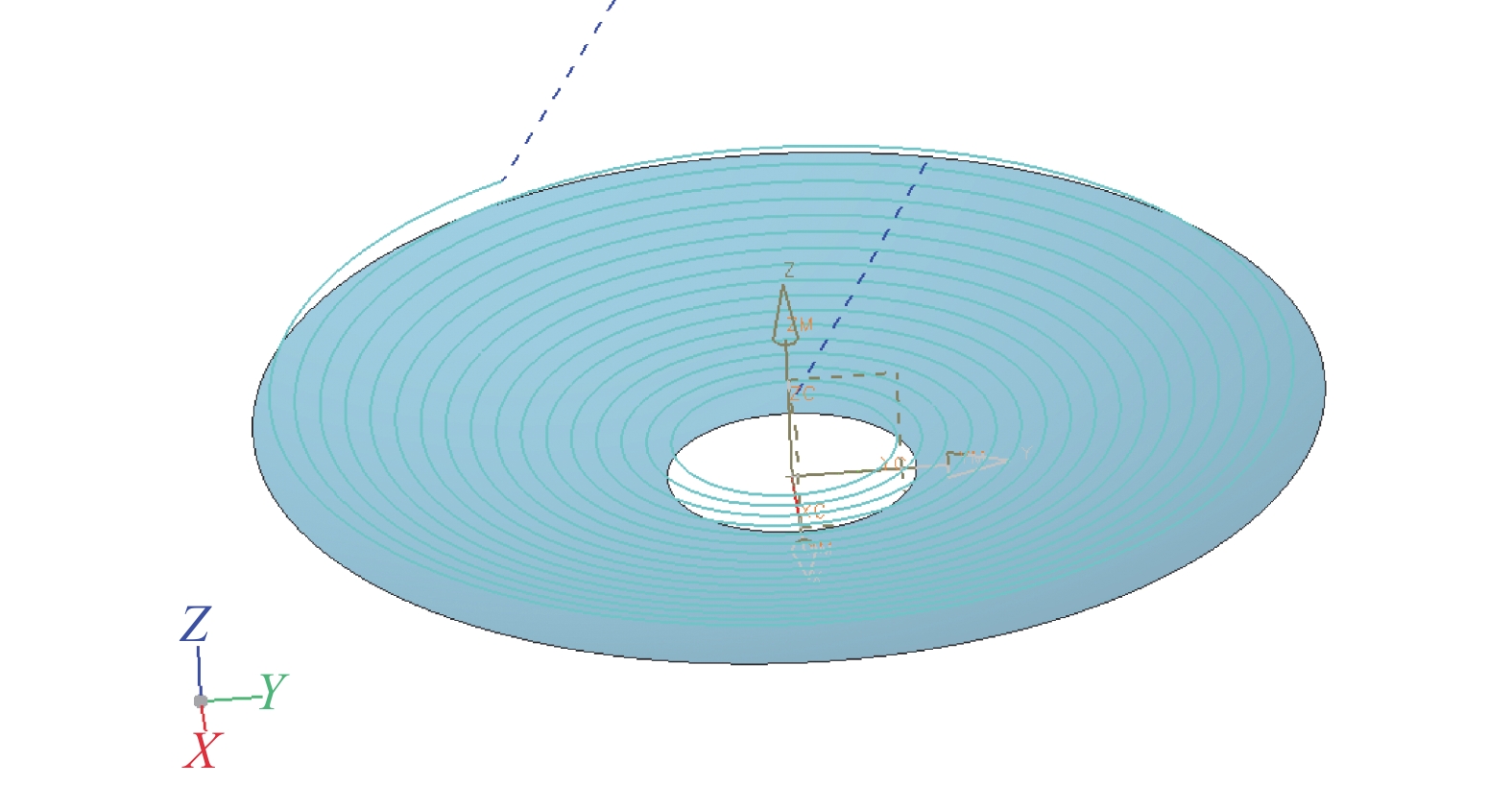
大口径碳化硅反射镜背部的轻量化孔的主要形式有三角形、正方形、扇形以及复合型等。但无论采用哪种形状的轻量化结构,结构框架都非常薄,会使反射镜的刚度降低,系统基频降低,使反射镜铣磨加工过程中容易产生共振。文中所加工的反射镜采用了背部三点支撑式的半封闭式轻量化结构,如图3所示。

图 3 反射镜背部轻量化结构
Figure 3. Lightweight structure on the back of the reflector
振动对于铣磨加工会产生较大影响,轻微颤振会使反射镜表面出现振纹,影响加工精度,降低加工效率。当外界激励频率与反射镜固有频率接近时还会发生共振[10-11],造成镜子表面断裂从而导致加工失败。对于反射镜铣磨加工,砂轮的转速为$ {n_s} $,则砂轮对于反射镜的激励频率$ {f_s} $的计算公式为:
$$ {f_s} = \frac{{{n_s}}}{{60}} $$ (3) 假设反射镜的固有频率为$ {f_m} $,根据动力学原理,反射镜动态响应位移$ X $与静变形$ {\delta _{st}} $的幅值比为:
$$ \dfrac{X}{{{\delta _{st}}}} = \dfrac{1}{{{{\left[ {{\left({1 - \left( { {{{f_s}}}/{{{f_m}}}} \right)}^2\right)^2} + \left( 2\zeta {{{{f_s}}}/{{{f_m}}}} \right)^2} \right]}^{1/2}}}} $$ (4) 式中:$ \zeta $表示系统的阻尼比。定义$\; \beta $为砂轮激励频率与反射镜固有频率值比,则:
$$ \beta = \frac{{{f_s}}}{{{f_m}}} $$ (5) 将公式(5)代入公式(4)中,则:
$$ \frac{X}{{{\delta _{st}}}} = \frac{1}{{{{\left[ {{{\left( {1 - {\beta ^2}} \right)}^2} + {{\left( {2\zeta \beta } \right)}^2}} \right]}^{1/2}}}} $$ (6) 在不同频率比与不同阻尼比下,受外界激励的系统的动态位移响应与静位移的幅值比曲线如图4所示。可以看出,阻尼比越小,幅值比值越大,对应的波峰越尖锐。但对于大阻尼系统而言,曲线的波峰较宽胖,且阻尼越大,共振峰越宽胖,波峰越平缓。对于有阻尼系统而言,当外界的激励频率在系统固有频率的共振带范围内时,即当${{\sqrt 2 }}/{2} > \beta > \sqrt 2 $时系统会发生共振。对于反射镜铣磨而言,为保证加工精度,砂轮的转速通常无法做出大幅度调整,因此,为避免共振的发生,需要改变镜子本身的固有频率,文中采用辅助支撑镜子边缘的方法。

图 4 系统动态位移响应与静位移的幅值比曲线
Figure 4. Plot of the ratio between dynamic displacement response and static displacement
-
大口径反射镜在设计时需要进行有限元仿真分析[12-13],内容主要包括重力、温升、强制位移、扫频和模态等。现代空间光学系统对反射镜的表面面形改变量要求十分严格,通常要求反射镜在X、Y、Z三个方向重力的作用下和在太空中温度变化时热变形的影响下的面形精度变化量小于10 nm。而CAE仿真可以在反射镜结构设计时为设计者提供参考。为观察反射镜表面在铣磨力的作用下产生的应力分布情况,文中进行仿真分析。为防止数据出现偶然性,分别在镜面Ф=160、260、360、460、500 mm的环带上各取四个点作为应力仿真的位置点,选取点的位置如图5所示。
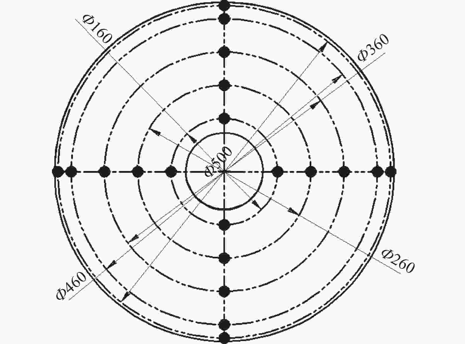
图 5 仿真铣磨点的位置选取图
Figure 5. Location selection of simulation milling points
假设对各仿真点施加的法向载荷力为$ {F_n} $,砂轮与工件贴合面积为$ {S_n} $,则:
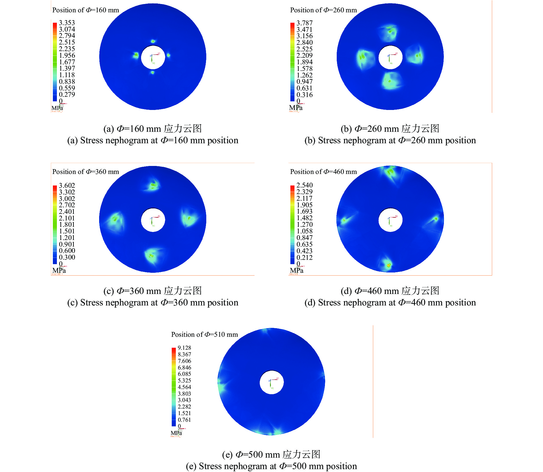
$$ {F_n} = \frac{{{M_n}}}{{{L_n}}} $$ (7) $$ {S_n} = {d_n} \times {R_n} $$ (8) 式中:$ {M_n} $为砂轮所受力矩;$ {L_n} $为砂轮杆的长度;$ {d_n} $为磨削深度;$ {R_n} $为砂轮的圆角尺寸。根据实际砂轮的选择,确定$ {F_n} $为40 N,$ {S_n} $为4×10⁻⁶ m2。不同径向位置的极限压力如表1所示,应力云图如图6所示。从图6中可以看出,在径向位置小于460 mm时铣磨应力较小,但在径向位置为500 mm的镜面边缘位置由于应力集中会出现应力激增的现象,但数值远低于碳化硅的极限抗压强度224 MPa。对于同一径向尺寸,不同位置的四个铣磨点,应力分布情况没有明显区别。由此可知,在铣磨加工过程中保护镜面边缘不破裂十分重要。
表 1 不同径向位置的极限压力
Table 1. Ultimate pressure at different radial positions
Radial positions/mm Ultimate pressure/MPa 160 3.353 260 3.787 360 3.602 460 2.540 500 9.128 
图 6 铣磨应力仿真结果
Figure 6. Simulation results of milling stress
-
为抑制反射镜的振动,提高系统的固有频率,文中采用一种支撑环对反射镜边缘进行支撑,支撑环与反射镜的装配方式如图7所示。为分析反射镜和支撑环在铣磨过程中的振动状态,判断反射镜是否与铣磨砂轮发生共振。对反射镜和支撑环整个系统进行了模态分析,仿真的边界条件为20 ℃,一个标准大气压。分析结果如表2所示,系统云图如图8所示。如对于铣磨加工,由于砂轮的转速限制,其频率一般在50~80 Hz之间,根据表中数据显示,砂轮激励频率与反射镜固有频率值比$\; \beta $远小于$ {{\sqrt 2 }}/{2} $,因此采用环形支撑对反射镜进行铣磨不会产生共振。

图 7 工装与反射镜装配图
Figure 7. Assembly diagram of tooling and reflector
表 2 系统的前六阶模态分析结果
Table 2. The first six modal analysis results of the system
Order Frequency/Hz 1 2469.1 2 2470.17 3 2880.09 4 4489.31 5 4497.48 6 4499.32 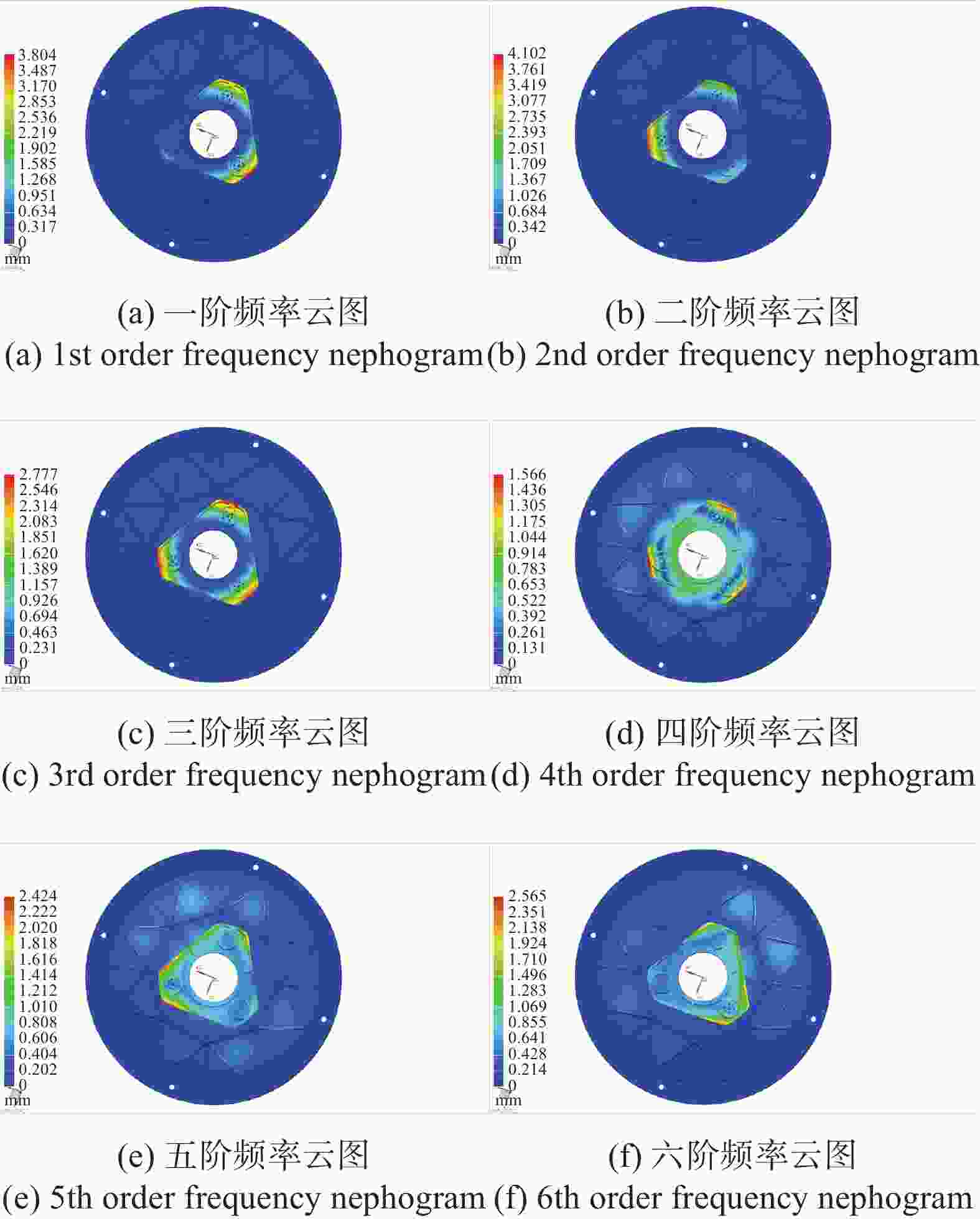
图 8 系统前六阶模态分析云图
Figure 8. The first six modal analysis nephogram of the system
-
选用DMU 125P五轴陶瓷加工中心对主反射镜进行铣磨,包括X、Y、Z三个平移轴和A、B两个旋转轴。机床实物图如图9所示,砂轮的材料采用树脂基金刚石杯形砂轮,铣磨过程(图10)中的主要参数如表3所示,加工过程中并未发生主反射镜与加工系统发生共振的现象。
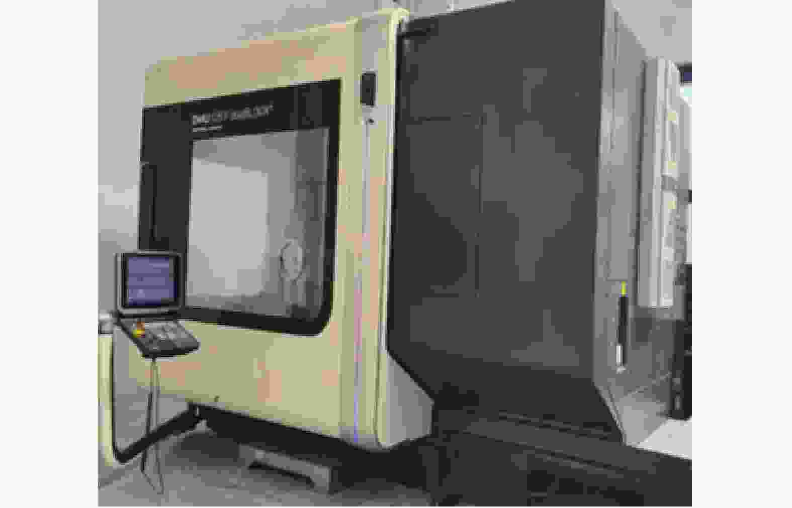
图 9 五轴加工中心实物图
Figure 9. Physical picture of five axis machining center
表 3 铣磨主要参数
Table 3. Main parameters of milling
Parameter Value Grinding wheel torque/N·m 2.5 Spindle speed/r·min–1 5000 Grinding wheel feed rate/mm 1.2 Milling depth/mm 0.1 
图 10 加工现场图
Figure 10. Processing site diagram
-
采用ZEISS生产的三坐标测量仪进行铣磨加工后表面面形精度的测量[14],该设备配备主动式扫描测针,具有优异的刚性 、较低的热膨胀性和轻盈的机身质量。X轴的最大行程为2100 mm,Y轴的最大行程为3200 mm,Z轴的最大行程为1250 mm。检测面形图如图11所示。最终面形精度检测结果PV值为3.5 μm,达到了进一步抛光的面形精度要求。

图 11 反射镜表面面形图
Figure 11. Surface profile of the mirror
-
针对目前对大口径超薄轻量化碳化硅反射镜表面粗加工难度大、周期长的问题,提出一种五轴高效超精密铣磨方法。采用平行给刀的铣磨方式,利用环形工装对反射镜边缘支撑进行辅助支撑,结合先进CAE仿真技术验证,对Ф510 mm的大口径轻量化碳化硅反射镜进行了快速铣磨加工。仿真及检测结果表明:相较于人工研磨,这种加工方法在保证了加工精度的前提下可将加工周期降低90%,且加工过程中不会出现镜面破坏以及系统的共振。该方法已成功用于大口径超薄轻量化碳化硅反射镜的粗加工,能够代替传统研磨方法,可作为其他大口径反射镜加工的技术参考。
Ultra-precision milling technology of large-aperture ultra-lightweight SiC mirror (invited)
-
摘要: 在分析了超轻量化大口径碳化硅(SiC)反射镜(轻量化率≥90%)表面去除原理和难点的基础上,为了实现此类型反射镜的快速加工,提出了一种采用有限元分析进行验证的五轴高效超精密铣磨方法。通过对反射镜铣磨过程中产生共振的机理进行分析,解释了共振的原因,利用有限元分析方法进行仿真模拟,验证了加工过程镜面不会被破坏且系统不发生共振,设计环形工装支撑并对口径Ф510 mm、壁厚 4 mm、轻量化率92%的SiC反射镜进行快速铣磨加工。反射镜初始面形峰谷(PV)值为956.1 μm,镜面去除量为1 mm,加工时间仅为48 h,相较于人工研磨研制周期降低了90%。通过检测,反射镜面形PV值为3.5 μm,满足反射镜抛光前面形精度优于4 μm的要求。Abstract:
Objective With the increasing requirement of satellite imaging quality, the aperture of the main mirror of the optical system is also increasing, and the large-aperture mirror must be designed with lightweight structure. In order to improve the processing efficiency, the main mirror needs to be roughed before polishing to remove the surface allowance during the sintering casting of the mirror embryo, but the ultra-thin and lightweight design of the mirror makes roughing very difficult. On the one hand, the ultra-thin mirror increases the brittleness of the mirror itself, and it is easy to crack the mirror surface by excessive stress during processing. On the other hand, the design of the lightweight hole on the back of the mirror will reduce the stiffness and natural frequency of the mirror, resulting in the mirror easily resonating with the processing system during the milling process, so that the mirror is destroyed. At present, manual grinding or ultrasonic vibration milling methods are generally used for rough machining, but these two processing methods have low surface removal efficiency and long processing cycle, which can't meet the needs of space optical systems for development cycle. Therefore, it is necessary to establish a milling method with higher surface removal efficiency and accuracy. For this purpose, an ultra-precision milling technology of large-aperture ultra-lightweight SiC mirror is established in this paper. Methods A five-axis high-efficiency milling ultra-precision machining method was proposed by using finite element analysis. Through the analysis of the resonance mechanism in the milling process of the mirror, the causes of resonance were explained (Fig.4). The finite element analysis method was adopted to simulate and verify that the mirror would not be damaged and the system would not have resonance during the machining process (Fig.6-8). An ultra-lightweight SiC mirror was quickly milling (diameter is 510 mm, the wall thickness is 4 mm, the lightweight rate is 92%) with the support of designed ring tooling (Fig.10). Results and Discussions The mirror is machined by means of parallel feed cutter, and the shape of the mirror is measured by interferometer. The initial Peak-to-Valley (PV) value of the mirror was 956.1 μm (Fig.11), the mirror removal amount is 1 mm, and the processing time is only 48 h, which is 90% lower than that of manual grinding. The PV value of surface is 3.5 μm (Fig.11), which meets the requirement that the PV value before mirror polishing should be better than 4 μm. The experimental results show that the scheme is feasible and can be used for high-efficiency and high-precision machining of large-caliber ultra-lightweight mirror Conclusions Aiming at the problem that the surface roughness of large-caliber ultra-thin lightweight silicon carbide mirror is difficult and the cycle is long, a five-axis high-efficiency ultra-precision milling method is proposed. Using the milling method of parallel cutter feeding, the annular tool was used to assist the edge support of the mirror, and the advanced CAE simulation technology was used to verify the fast milling process of the large diameter Ф510 mm lightweight silicon carbide mirror. Simulation and testing results show that compared with manual grinding, this processing method can reduce the processing cycle by 90% under the premise of ensuring the processing accuracy, and there is no mirror damage and system resonance in the processing process. This method has been successfully used in the rough machining of large-diameter ultra-thin lightweight silicon carbide mirror, which can replace the traditional grinding method and can be used as a technical reference for other large-diameter mirror machining. -
Key words:
- milling and grinding /
- SiC mirror /
- finite element analysis /
- ultra-lightweight
-
图 4 系统动态位移响应与静位移的幅值比曲线
Figure 4. Plot of the ratio between dynamic displacement response and static displacement
表 1 不同径向位置的极限压力
Table 1. Ultimate pressure at different radial positions
Radial positions/mm Ultimate pressure/MPa 160 3.353 260 3.787 360 3.602 460 2.540 500 9.128  下载: 导出CSV
表 2 系统的前六阶模态分析结果
Table 2. The first six modal analysis results of the system
Order Frequency/Hz 1 2469.1 2 2470.17 3 2880.09 4 4489.31 5 4497.48 6 4499.32
下载: 导出CSV
表 3 铣磨主要参数
Table 3. Main parameters of milling
Parameter Value Grinding wheel torque/N·m 2.5 Spindle speed/r·min–1 5000 Grinding wheel feed rate/mm 1.2 Milling depth/mm 0.1
下载: 导出CSV
-
[1] Robichaud J L, Schwartz J, Landry D, et al. Recent advances in reaction bonded silicon carbide optics and optical systems [C]//Proceedings of SPIE, 2005, 5868: 586802. [2] 徐宏, 关英俊. 大口径SiC轻量化反射镜组件的结构设计[J]. 红外与激光工程, 2014, 43(S1): 83-88. doi: 10.3969/j.issn.1007-2276.2014.z1.015 Xu H, Guan Y J. Structural design of large aperture SiC mirror subassembly [J]. Infrared and Laser Engineering, 2014, 43(S1): 83-88. (in Chinese) doi: 10.3969/j.issn.1007-2276.2014.z1.015 [3] 凤良杰, 成鹏飞, 王炜. Φ450 mm口径空间天文相机轻量化碳化硅主反射镜组件设计[J]. 红外与激光工程, 2021, 50(02): 191-197. Feng L J, Cheng P F, Wang W. Design of Φ450 mm light-weighted SiC mirror subsystem in space-based astronomy telescope [J]. Infrared and Laser Engineering, 2021, 50(2): 20200175. (in Chinese) [4] Chen Xi, Dai Zhuocheng, Guo Peiji, et al. Study on generating method for off-axis aspherical mirrorgrinding based on five axis machining center [J]. Optical Technique, 2022, 48(1): 55-59. doi: 10.13741/j.cnki.11-1879/o4.2022.01.003 [5] 于建海, 于秋跃, 房安利等. 大口径碳化硅反射镜高效铣磨实时补偿技术[J]. 光学技术, 2020, 46(04): 502-506. DOI: 10.13741/j.cnki.11-1879/o4.2020.04.021. Yu J H, Yu Q Y, Fang A L. Real-time compensation of high efficiency grinding for the large aperture mirror. [J]. Optical Technique, 2020, 46(4): 502-506. (in Chinese) doi: 10.13741/j.cnki.11-1879/o4.2020.04.021 [6] Chanda A, Dwivedy S K. A study of nonlinear behavior of flexible tool and workpiece in turning operation with regenerative effect under internal and primary resonance conditions [J]. Journal of Computational and Nonlinear Dynamics, 2020, 15(6): 061004. [7] Zhang Zikang, Yuan Songmei, An Wenzhao, et al. FEM simulation investigation of ultrasonic vibration-assisted grinding of SiC/SiC composites [J]. Journal of Physics: Conference Series, 2022, 2348(1): 012011. [8] 王振忠, 施晨淳, 张鹏飞等. 先进光学制造技术最新进展[J]. 机械工程学报, 2021, 57(08): 23-56. doi: 10.3901/JME.2021.08.023 Wang Zhenzhong, Shi Chenchun, Zhang Pengfei, et al. Transient thermal analysis for grinding fabrication of hard and brittle material [J]. Journal of Mechanical Engineering, 2021, 57(8): 23-56. (in Chinese) doi: 10.3901/JME.2021.08.023 [9] 张志宇, 李锐钢, 郑立功等. 离轴非球面SiC反射镜的精密铣磨加工技术[J]. 机械工程学报, 2013, 49(17): 39-45 doi: 10.3901/JME.2013.17.039 Zhang Z Y, Li Y G, Zheng L G, et al. Precision grinding technology for the off-axis aspherical silicon carbide mirror blank [J]. Journal of Mechanical Engineering, 2013, 49(17): 39-45. (in Chinese) doi: 10.3901/JME.2013.17.039 [10] Benardos P G, Mosialos S, Vosniakos G C. Prediction of workpiece elastic deflections under cutting forces in turning [J]. Robotics and Computer Integrated Manufacturing, 2005, 22(5): 505-514. [11] 赵宇, 苏成志, 赵贵军等. Φ500 mm超轻量化SiC反射镜结构优化设计[J]. 中国光学, 2020, 13(06): 1352-1361. doi: 10.37188/CO.2019-0201 Zhao Y, Su Z C, Zhao G J, et al. Structural optimization for the design of an ultra-lightweight SiC mirror with a diameter of 500 mm [J]. Chinese Optics, 2020, 13(6): 1352-1361. (in Chinese) doi: 10.37188/CO.2019-0201 [12] Gao G F, Zhao B, Hui D, et al. Research on the force characteristics in ultrasonic grinding nano-zirconia ceramics [C]//Advances in Machining & Manufacturing Technology IX, 2008: 258-262. [13] Yang L, Xie X G. Transient thermal analysis for grinding fabrication of hard and brittle material [J]. Journal of Mechanical Engineering, 2014, 43(S1): 169-176. [14] 王孝坤, 戚二辉, 胡海翔等. 超大口径平面反射镜的光学检测(特邀)[J]. 红外与激光工程, 2022, 51(01): 396-402. Wang X K, Qi E H, Hu H X, et al. Optical testing of the super-large plane mirror (Invited) [J]. Infrared and Laser Engineering, 2022, 51(1): 20210953. (in Chinese) -

 点击查看大图
计量
- 文章访问数: 133
- HTML全文浏览量: 17
- PDF下载量: 41
- 被引次数: 0

