


-
离轴三反光学系统不仅具有反射式光学系统易于实现大口径、长焦距的优点[1],兼具可以同时校正球差、彗差、像散,无中心遮拦[2],可实现大视场等优势,在成像光学领域有着广泛应用。得益于自由曲面理论和设计方法的发展,越来越多先进的光学系统应用自由曲面实现高性能的设计。在离轴三反光学系统中,自由曲面的应用可以扩大系统的视场[3-5],提高系统的像质[6-7]。随着对光学系统成像指标要求的不断提高,离轴三反光学系统向着大口径、长焦距的方向不断发展,同时光学系统的像差随着焦距与口径的增大呈幂指数增长,微小的扰动即可带来大幅的像质退化,误差敏感度的增大给光学系统带来了极为严苛的公差要求,给光学系统的有效实现带来了极大的挑战。
误差敏感度表征了光学系统在误差条件下像质变化的敏感程度,是衡量光学系统可实现性的重要指标,具备低误差敏感度特征的光学系统不仅可以更好地抵抗直接或间接误差带来的像质退化[8],而且可以实现光学系统像质和成本之间的最佳平衡[9]。因此,开展对光学系统的低误差敏感度设计方法研究,对光学系统的设计与实现具有重要的理论和现实意义。
目前较为典型的光学系统降敏设计方法[10]有全局优化法[11-13]、多重结构法[14-15]、参数控制法[16-21]和自由曲面面型优化法[22-23]等。全局优化法是对在解空间内已实现良好像质的光学系统进行大样本迭代与优化,从大量的设计样本中选择公差鲁棒性好的光学系统的方法。全局优化法可以在一定范围内获得误差敏感度最优的光学系统,但是对计算机硬件要求高且耗时长。多重结构法是指采用多种误差类型模拟光学系统在生产加工和实际应用过程中可能产生的误差,在光学系统初始结构的基础上,建立包含不同误差的多重结构,对初始结构和包含不同误差的多重结构同步优化,优化后所有系统的像质仍在可接受范围之内。光学系统中的一些参数与误差敏感度高度相关,且其中的部分参数与误差敏感度具有严格的数学关系,研究人员针对这些参数开展了一系列的数学分析,并建立了以参数控制为核心的误差敏感度优化方法。自由曲面面型优化法是指在光学系统中将部分光学元件设为自由曲面进行误差敏感度优化的方法。笔者团队针对同一初始结构,探究了不同面型对光学系统误差敏感度的影响,研究表明,合理应用自由曲面可以显著降低光学系统误差敏感度。
团队前期采用光线追迹的方法,以像差理论为指导,严格推导了光学系统的内部参数与误差敏感度的数学关系,提出了角度优化降敏设计方法[19]和局部曲率控制降敏设计方法[20]两种以参数控制为核心的降敏设计方法。文中采用两种设计方法分别对一个大型自由曲面离轴三反光学系统进行了降敏优化设计,所得光学系统均成像质量良好,调制传递函数(Modulation Transfer Function, MTF)接近衍射极限。对施加倾斜误差的光学系统进行了误差敏感度分析,结果显示,使用两种降敏设计方法降敏优化后的光学系统误差敏感度均得到有效降低,且采用局部曲率控制降敏设计方法设计的光学系统的误差敏感度更低。
-
光学元件位置误差是引起光学系统像质退化的重要因素。倾斜误差是位置误差的一类典型表现形式,会在光学系统中引入场常数彗差、场线性像散等难以用离焦补偿的像差[21],一直被视为光学系统误差敏感度研究中的重点内容。
光学系统失调后的像质退化程度即为光学系统的误差敏感度,降敏设计方法的研究始于选择合适的像质评价标准,已知的像质评价标准有光程差、MTF、波像差、几何像差等,选择以光程差和波前误差这两种标准评价光学系统像质,以光学系统失调前后像质评价标准的变化量为基准表征光学系统误差敏感度。采用几何光学的方法,模拟倾斜误差产生前后光线追迹的数学模型,通过推导光学系统内部参数与像质之间的数学关系,进而获得光学系统内部参数与误差敏感度之间的数学关系,构建出了两种误差敏感度评价函数,根据不同的误差敏感度评价函数提出了以下两种适用于自由曲面光学系统的降敏设计方法。
-
角度优化降敏设计方法以单镜光学系统为基本模型,以光学系统扰动前后任意光线的光程差(Optical Path Difference, OPD)作为误差敏感度标准。当光学系统受到误差扰动时,光程差变化量ΔOPD越小,光学系统误差敏感度越低。
单镜反射式光学系统倾斜误差产生前后光线传播数学模型如图1所示,Z轴为光轴,O点为光轴与镜面的交点,光阑位于单镜前,边缘光线为沿着光阑边缘入射的光线,主光线为沿光轴入射的光线,边缘入射光线与镜面的交点为A,单反射镜绕X轴产生ε角度倾斜误差后边缘入射光线与镜面交点为A',B、B'所在平面为像面。

图 1 单镜反射式光学系统光程差数学模型
Figure 1. Mathematical model for OPD of single-mirror reflective optical system
倾斜误差产生前光学系统光程差为:
$$ OPD = HA + AB - (BO + OB) $$ (1) 倾斜误差产生后光学系统光程差为:
$$ OPD' = HA' + A'B' - (B'O + OB) $$ (2) 因此,光学系统在误差扰动前后光程差变化量为:
$$ \Delta OPD = AA' + A'B' - AB + OB' - OB $$ (3) 运用解析几何的方法分析得知,在倾斜误差恒定的情况下,公式(3)中的AA'与OB'−OB均为常数,仅A'B'−AB一项与入射角i呈正相关,即倾斜误差扰动前后光学系统光程差ΔOPD与入射角i呈正相关。当镜面受到倾斜误差影响时,镜面入射角越大的光学系统,ΔOPD越大,光学系统的误差敏感度越高。在两镜和多镜系统模型中进行误差扰动分析,所得结论与单镜系统一致。
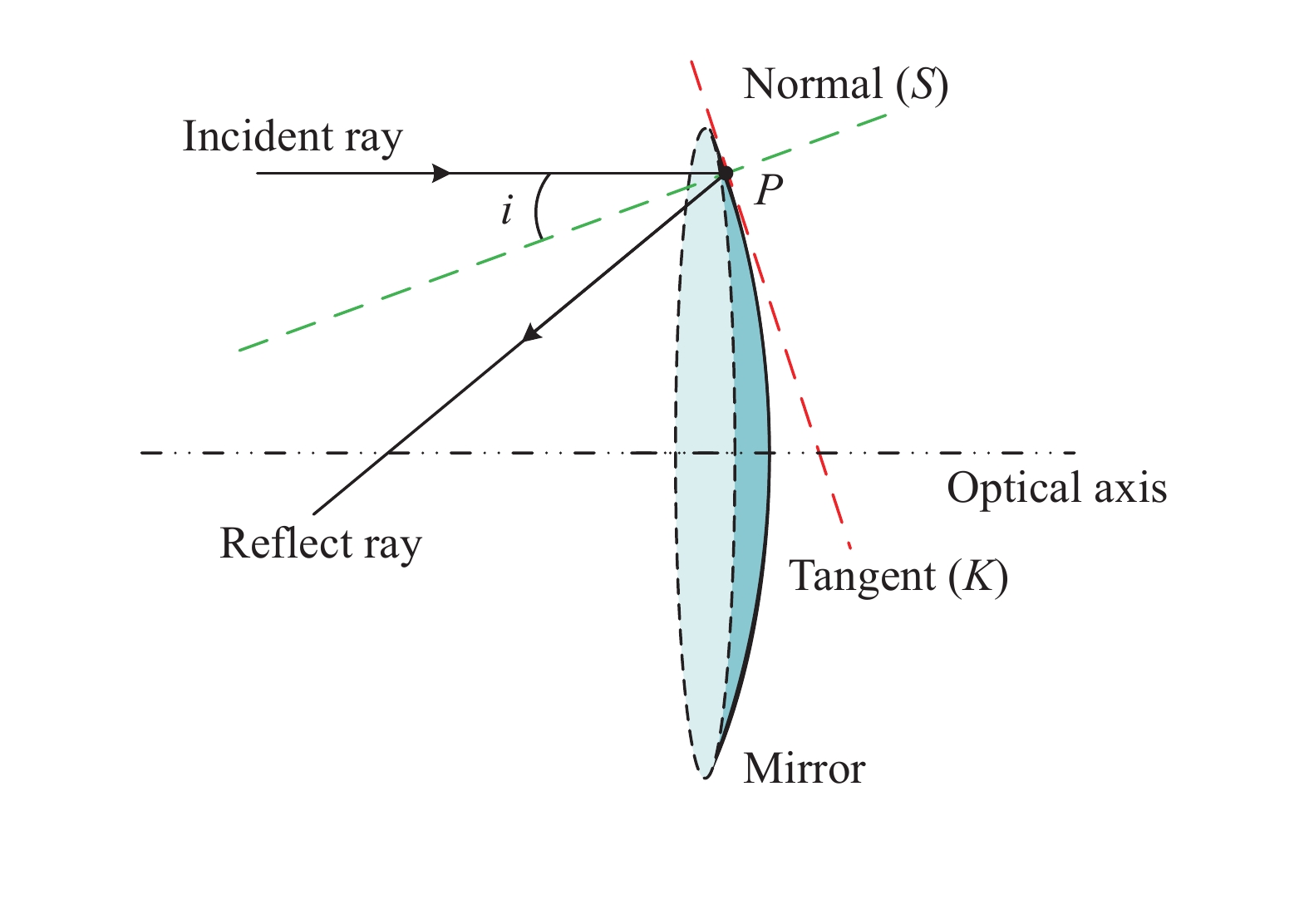
在光学系统降敏设计过程中可以通过控制入射光线与镜面交点处镜面的切线斜率K来控制光线的入射角度,进而控制光学系统倾斜误差敏感度。光学系统降敏优化过程中期望将误差敏感度降为零,此时K值趋近于无穷大,难以设定切线斜率的阈值,因此,笔者提出通过控制入射光线与镜面交点处的法线斜率S来控制光学系统的倾斜误差敏感度,S值越小,误差敏感度越低,光线入射角与切线斜率K、法线斜率S的关系如图2所示。

图 2 光线入射角与切线斜率(K)、法线斜率(S)关系图
Figure 2. Relation diagram of ray incidence angle with tangent slope (K) and normal slope (S)
定义倾斜误差敏感度评价函数为S:
$$ S = \frac{{\displaystyle\sum\limits_{m = 1}^M {\displaystyle\sum\limits_{h = 1}^H {\sqrt {\displaystyle\sum\limits_{n = 1}^N {S_{n,h,m}^2} } } } }}{{M \times H}} $$ (4) 式中:n为光学系统中镜面序号;m为光学系统中视场点的序号;h为每个视场点中的光线序号;N为光学系统中镜面数量;M为光学系统中视场点数;H为每个视场点中采样的光线的数量。
角度优化降敏设计方法是以反射式光学系统为起点进行归纳推理,其原理具备普适性,对透射式光学系统[8],以及非球面、自由曲面光学系统[24]的降敏设计也同样适用。
-
局部曲率控制降敏设计方法是一种直接针对自由曲面光学系统进行降敏设计的方法,自由曲面通常可视为在球面或二次曲面基底上叠加高次项所得非旋转对称曲面面型。局部曲率控制降敏设计方法采用“微元”的思想,微元分割法示意图如图3所示,可以将复杂的自由曲面光学表面视为数个小曲面的组合,当微元足够小,小至可近似为一个点时,该微元可以视为一个圆锥曲面进行分析。因此,在对光学自由曲面进行降敏设计时,应当采样尽可能多的视场点和入射光线,通过降低该面上采样的每根入射光线对应的圆锥曲面的误差敏感度(局部误差敏感度)来实现整个光学自由曲面的降敏优化设计。

图 3 微元分割法示意图
Figure 3. Schematic diagram of microelement segmentation method
局部曲率控制降敏设计方法以波前误差(Wavefront Error, WE)作为光学系统扰动前后的像质评价标准,在倾斜误差扰动前后,光学系统波前误差变化量ΔWE越小,光学系统误差敏感度越低。
任意一根入射光线与镜面交点处的反射镜镜面都可以视为一个圆锥曲面微元,倾斜误差产生前后单镜反射式光学系统波前误差光线追迹的数学模型如图4所示,光轴Z轴与镜面交点为O点,单反射镜绕X轴产生ε角度倾斜误差,那么误差产生前后该微元针对同一入射光线HA(At)的波前误差变化量为:
$$ \Delta WE = A{A_t} + {A_t}{B_t} - AB $$ (5) 通过几何光学推导可知,当倾斜误差不变时,公式(5)中AAt为恒值,AtBt−AB与微元曲率c呈正相关,即微元曲率c与误差敏感度正相关,当镜面产生倾斜误差时,该微元所对应的二次曲面曲率越小,该微元的倾斜误差敏感度越小。
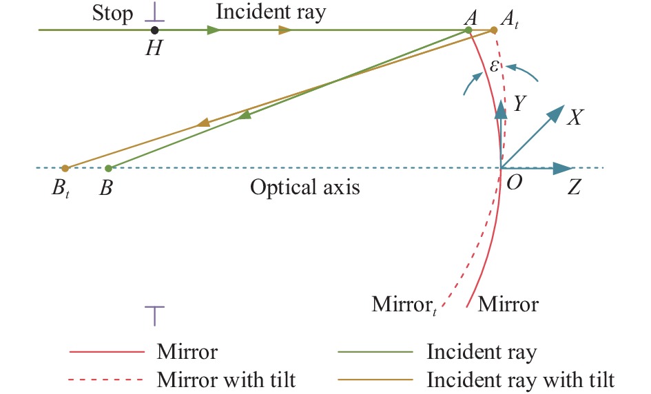
图 4 单镜反射式光学系统波前误差数学模型
Figure 4. Mathematical model for WE of single-mirror reflective optical system
复杂的自由曲面是由无数个微元组成的,在光学系统实际设计过程中难以控制曲面上所有的点,可以通过对视场和光瞳采样,选择大量的“微元”进行降敏优化,因此提出评价函数LC用于自由曲面光学系统降敏设计。
定义单个镜面单一视场点的倾斜误差敏感度评价函数LCS,F为:
$$ L{C_{S,F}} = \sqrt {\frac{{\displaystyle\sum\limits_{u = 1}^{NOR} {\displaystyle\sum\limits_{v = 1}^{NOA} {LC_{u,v}^2} } }}{{NOR \cdot NOA}}} $$ (6) 式中:NOR为光瞳采样环数;u为环的序号;NOA为光瞳采样臂数;v为臂的序号。整个光学系统的倾斜误差敏感度评价函数LC为:
$$ LC = \dfrac{{\displaystyle\sum\limits_{m = 1}^{NOF} {\sqrt {\displaystyle\sum\limits_{n = 1}^{NOS} {\frac{{LC_{S,F}^2}}{{NOS}}} } } }}{{NOF}} $$ (7) 式中:NOS为光学系统中光学表面数;n为光学系统中光学表面序号;NOF为采样视场点数量;m为视场点序号。
-
大型离轴三反光学系统降敏优化设计流程图如图5所示,主要分为三个步骤:

图 5 大型自由曲面离轴三反光学系统降敏优化设计流程图
Figure 5. Flow chart of desensitization optimization design for large freeform off-axis three-mirror optical systems
(a) 根据设计指标选择光学系统构型,计算初始同轴光学系统结构,再进行同轴系统离轴化以消除光线遮拦和交叉;
(b) 像质优化与面型选择。对光学系统中的光线进行采样,优化系统像质,若系统满足像质要求,则执行下一步;若不满足像质要求,选择低误差敏感度的非球面或自由曲面进行像质优化,直至满足像质要求,执行下一步。
(c) 误差敏感度优化。步骤(b)得到的满足像质要求的光学系统称为初始结构,采用误差敏感度评价函数对光学系统初始结构进行误差敏感度评价,根据初始结构设置结构约束条件和像质要求,逐步降低评价函数值,对光学系统进行降敏优化,当继续降低评价函数,优化后光学系统不满足要求为止降敏结束,得到低误差敏感度的大型自由曲面离轴三反光学系统。
步骤(b)中,面型选择根据对不同曲面面型敏感度的排序[24]来选择低误差敏感度的非球面和自由曲面。
光学系统降敏设计方法的核心是误差敏感度评价函数,采用角度优化降敏设计方法和局部曲率控制降敏设计方法对光学系统进行降敏设计时,只有上述流程中的步骤(c),即误差敏感度评价函数不同,角度优化降敏设计方法采用评价函数S进行敏感度评价与降敏优化,局部曲率控制降敏设计方法采用评价函数LC进行敏感度评价与降敏优化。
-
文中选择具有中继像面的COOK TMA光学系统作为初始结构,并将主镜设置为光阑[25]。
在同轴三反光学系统结构中,次镜与主镜、三镜与次镜的遮拦比分别是α1、α2,次镜与三镜的放大率分别为β1、β2。
由于反射式光学系统只有单色像差,可以根据三级像差理论得出光学系统轮廓系数与结构尺寸的关系,进而求得系统中三面反射镜的曲率半径与间距。
笔者所设计的大型离轴三反光学系统指标要求如表1所示,系统焦距为30 000 mm,总长小于10 000 mm,视场为1°×1°。根据给定设计指标,令次镜遮拦比α1=0.148、次镜放大率β1=−1.975,三镜遮拦比α2=−2.000、三镜放大率β2=2.746,系统满足平像场条件,求解光学系统曲率半径与间距,获得小像差初始同轴三反光学系统,对同轴三反光学系统进行孔径离轴得到初始离轴三反光学系统。
表 1 光学系统指标要求
Table 1. Optical system index requirements
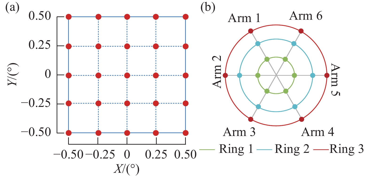
Parameter Specification Focal length/mm 30000 F number 15 FOV/(°) 1×1 Entrance pupil diameter/mm 2 000 Wavelength/nm 632.8 Configuration Off-axis TMA Total length/mm <10000 为了方便后续对像质和敏感度进行优化,对光学系统内光学表面的光线进行采样,在1°×1°的方形视场内均匀选择25个视场点,视场采样如图6(a)所示,每个视场点内均采用三环六臂的方法选择18根光线,光瞳采样如图6(b)所示,即在每个光学系统中选择450根光线进行后续优化设计。

图 6 光线采样图。(a)视场采样图;(b)光瞳采样图
Figure 6. Light sampling diagram. (a) FOV sampling diagram; (b) Pupil sampling diagram
初始离轴三反光学系统的三面反射镜均为圆锥曲面,自由度少,像差校正能力有限。非球面与自由曲面可以增加光学系统自由度,提高像质,在TMA光学系统设计过程中,为了降低制造成本和复杂性,应选用尽量少的自由曲面和适量的非球面[7],因此主镜、次镜选为非球面、三镜选用自由曲面,根据对不同曲面面型倾斜误差敏感度的排序[23],在非球面中选择Q-type非球面,在自由曲面中选择XY多项式自由曲面。将初始系统的主镜、次镜设置为Q-type非球面,三镜设置为XY多项式自由曲面。对光学系统像质进行优化,优化后得到系统1,其结构布局图如图7(a)所示,MTF曲线如图7(b)所示,系统的MTF接近衍射极限,系统1的全视场波像差如图7(c)所示,波像差平均值为0.038λ (λ=632.8 nm),25个视场的最大波像差为1/15λ。以系统1为初始结构进行后续降敏设计。

图 7 像质优化后得到的初始系统——系统1:(a)系统布局图,(b) MTF图,(c)全视场RMS WFE图
Figure 7. Initial system obtained after image quality optimization-System 1: (a) System layout, (b) MTF diagram, (c) RMS WFE diagram of full FOV
-
系统1为满足设计指标要求的初始结构,分别使用两种降敏设计方法中的评价函数对系统1进行误差敏感度评价。以评价函数S评价系统1的敏感度时,S值为0.120;以评价函数LC评价系统1的敏感度时,LC值为0.080。
分别以两种降敏设计方法对系统1进行降敏设计,在降敏设计优化过程中要求光学系统的离轴量不变且系统构型不变,光学系统总长小于10000 mm且应与系统1差异尽量小,波像差平均值为0.038×(1±5%)λ,25个视场最大波像差不超过1/15λ,且光学系统中光线与中继像面无遮拦与交叉。
将系统1的评价函数值设置为降敏起点,逐步降低评价函数值,并且进行像质优化,降敏优化到光学系统结构或像质不满足要求为止,即可获得使用该降敏设计方法能获得的误差敏感度最低的光学系统。
采用角度优化降敏设计方法以S=0.120为起点进行降敏设计,降至S=0.111为止得到系统2,采用局部曲率控制降敏设计方法以LC=0.080为起点进行降敏设计,降至LC=0.072为止得到系统3,系统2的结构布局如图8(a) 所示,系统3结构布局如图8(b)所示,系统1、系统2、系统3结构布局无显著差异,且光学系统中光线均无遮拦与交叉。系统2、系统3的MTF如图8(c)、图8(d)所示,系统2和系统3的MTF均接近衍射极限;系统2的全视场波像差如图8(e)所示,波像差平均值为0.039λ,系统3的全视场波像差如图8(f)所示,波像差平均值为0.036λ,系统2和系统3的全视场波像差最大值均小于1/15λ,系统2和系统3的波像差均满足指标要求。

图 8 角度优化降敏设计方法优化后的光学系统——系统2,局部曲率控制降敏设计方法优化后的光学系统——系统3。光学系统布局图:(a) 系统2,(b) 系统3;MTF图:(c)系统2,(d)系统3;全视场RMS WFE图:(e)系统2,(f)系统3
Figure 8. Optical system optimized by angle optimization desensitization design method-System 2, optical system optimized by local curvature control desensitization design method-System 3. Optical system layout: (a) System 2, (b) System 3; MTF diagram: (c) System 2, (d) System 3; RMS WFE diagram of full FOV: (e) System 2, (f) System 3
-
将误差扰动前后波像差变化量ΔRMS WFE定义为光学系统误差敏感度的值,根据倾斜误差扰动(子午:0.001°,弧矢:0.001°)下, 2 000次蒙特卡洛公差分析结果计算光学系统误差敏感度。系统1、系统2、系统3的光学系统布局和像质均无显著差异,分别对系统1、系统2、系统3进行敏感度评价,系统1、系统2、系统3扰动后全视场波像差如图9(a)所示,在25个视场点,系统2、系统3在扰动后的波像差均比系统1扰动后的波像差小,说明角度优化降敏设计方法与局部曲率控制降敏设计方法均可以有效降低光学系统倾斜误差敏感度。在倾斜误差扰动下,使用局部曲率控制降敏设计方法降敏优化得到的系统3比使用角度优化降敏设计方法降敏优化得到的系统2波像差更低。
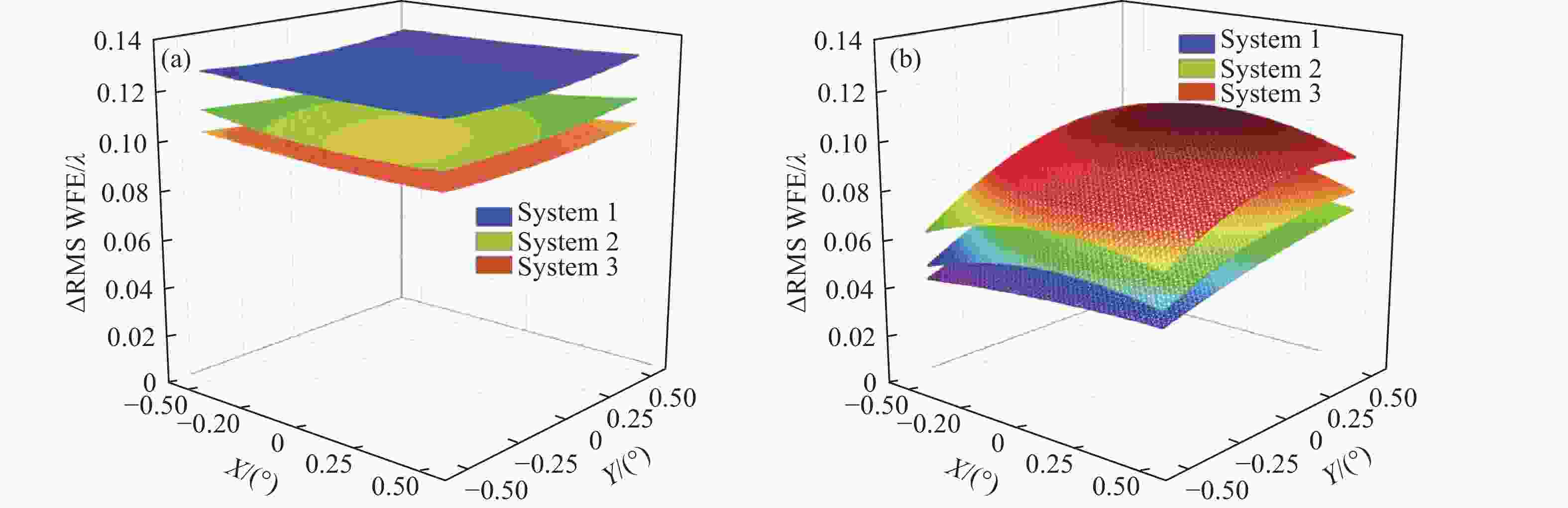
图 9 系统1、系统2、系统3 (a)倾斜失调后RMS WFE对比图及 (b)ΔRMS WFE对比图
Figure 9. (a) RMS WFE comparison diagram after tilt misalignment and (b) ΔRMS WFE comparison diagram of System 1, System 2 and System 3
系统1、系统2、系统3全视场的倾斜误差敏感度ΔRMS WFE对比如图9(b)所示,使用两种降敏设计方法设计的光学系统误差敏感度均优于初始系统。使用常规光学设计方法设计的系统1与使用两种降敏设计方法设计的系统2和系统3的RMS WFE设计值、误差敏感度平均值与系统总长对比如表2所示。系统2总长比系统1小2.58%,系统3总长比系统1大0.03%,三个系统总长无显著差异且构型相同,在三个系统的像质均满足指标要求的情况下,使用角度优化降敏设计方法将误差敏感度降低了17.98%,使用局部曲率控制降敏设计方法将误差敏感度降低了30.34%。
表 2 降敏设计方法对比
Table 2. Comparison of the desensitization methods
System Nominal value
RMS WFE/λΔRMS WFE
average value/λDesensitization
rateTotal
length/mmSystem 1
(only WFE)0.038 0.089 - 9097.23 System 2 (S) 0.036 0.073 17.98% 8862.07 System 3 (LC) 0.039 0.062 30.34% 9100.00 因此,针对同一大型自由曲面离轴三反光学系统初始结构,在构型、尺寸与像质均无显著差异的情况下,局部曲率控制降敏设计方法与角度优化降敏设计方法均可以有效降低光学系统误差敏感度,且局部曲率控制降敏设计方法的降敏效果优于角度优化降敏设计方法。
-
文中以一个焦距为30000 mm、F数为15、视场角为1°×1°的大型自由曲面离轴三反光学系统的设计为背景,采用角度优化降敏设计法和局部曲率控制降敏设计法对满足像质与尺寸要求的离轴三反初始结构进行降敏优化,结果表明,在光学系统布局和像质均无显著差异的情况下,角度优化降敏设计方法降敏优化得到的光学系统(系统2)将初始结构误差敏感度降低了17.98%,局部曲率控制降敏设计方法降敏优化得到的光学系统(系统3)将初始结构误差敏感度降低了30.34%。正确使用两种降敏设计方法均可以有效降低倾斜误差扰动下光学系统的误差敏感度,且局部曲率控制降敏设计方法的降敏效果更好。在光学系统设计过程中,正确应用降敏设计方法可以显著提升光学系统抵抗误差干扰的能力,有效节约大型自由曲面离轴三反光学系统实现的经济和时间成本,对大型光学系统的设计与建造具有重要意义。
Desensitization design of large freeform off-axis three-mirror optical system (invited)
-
摘要: 离轴三反光学系统基于无孔径遮拦、可实现大视场等优势,结合自由度高、像差校正能力强的光学自由曲面,可以实现优异的光学性能。光学系统成像指标的不断提高促使反射式光学系统的口径和焦距不断增大,光学系统误差敏感度剧增,加工难度和装调敏感度也随之提高,耗费的时间和经济成本巨大。误差敏感度可以表征光学系统在失调后的敏感程度,误差敏感度低的光学系统公差精度要求宽松,在优化过程中控制误差敏感度可以实现像质与成本之间的最佳平衡。因此,降敏优化是光学系统设计过程中不可或缺的一环。文中提出的角度优化降敏设计方法和局部曲率控制降敏设计方法对一个焦距30 000 mm、F数为15、视场角1°×1°的大型自由曲面离轴三反光学系统进行了降敏设计并进行对比,结果表明,在光学系统构型无显著差异的情况下,使用两种降敏设计方法降敏后的光学系统像差校正理论结果均表现优异,调制传递函数(MTF)均接近衍射极限,两种降敏设计方法均可以有效降低光学系统误差敏感度。对比发现,局部曲率控制降敏设计方法降敏效果更好。Abstract:
Objective Off-axis three-mirror optical systems, based on the advantages of non-obscuration and capable of achieving a large field of view (FOV), can exhibit excellent optical performance, combined with the optical freeform surface with high degrees of freedom and strong aberration correction ability. The improvement of the imaging requirements has led to the continuous increase of the aperture and focal length of the reflective optical system, the error sensitivity of the optical system increases dramatically, resulting in higher processing difficulty and alignment sensitivity, as well as substantial time and economic costs. Error sensitivity represents the sensitivity of optical system after misalignment. The tolerance accuracy of optical system with low error sensitivity is loose. By controlling error sensitivity during the optimization process, an optimal balance can be achieved between image quality and cost. Therefore, desensitization optimization is an indispensable part of the large freeform off-axis three-mirror optical system design process. Methods Low error sensitivity optical system design begins with the selection of image quality evaluation criteria that can characterize the error sensitivity. The optical path difference and wavefront error are selected as two image quality evaluation criteria, and the geometrical optics method is adopted to establish the mathematical model of ray tracing before and after misalignment (Fig.1, Fig.4). Then the mathematical relationship between the parameters of the optical system and the error sensitivity is obtained, two error sensitivity evaluation functions (S and LC) are constructed based on the mathematical relationship, and the angle optimization desensitization design method and the local curvature desensitization design method are proposed as two desensitization design methods applicable to freeform optical systems according to the evaluation functions. A desensitization design process for large freeform off-axis three-mirror optical systems is developed (Fig.5). Two proposed desensitization design methods are applied to desensitize a large freeform off-axis three-mirror optical system with a focal length of 30 000 mm, an F number of 15 and an FOV of 1°×1° (Tab.1), and the desensitization effect of the two methods is compared. Results and Discussions The initial structure of the large freeform off-axis three-mirror optical system is System 1 (Fig.7), the angle optimization desensitization design method is used to obtain System 2, and the local curvature control desensitization design method is used to obtain System 3. The modulation transfer function (MTF) of all three systems is close to the diffraction limit, and the average RMS WFE of System 1, System 2, and System 3 is 0.038λ, 0.036λ and 0.039λ respectively (Fig.8), the image quality of all three systems is in the range of 0.038× (1±5%)λ and less than 1/15λ of each FOV (Fig.8).The total length of System 1, System 2, and System 3 is9 097.23 mm, 8 862.07 mm and 9 100.00 mm (Tab.2) respectively. The three systems are identical in configuration and differ slightly in total length. Under the tilt error perturbation (tangential: 0.001°, sagittal: 0.001°), the error sensitivity (ΔRMS WFE) of System 1, System 2, and System 3 is 0.089λ, 0.073λ and 0.062λ respectively (Fig.9). The error sensitivity is reduced by 17.98% using the angle optimization desensitization design method and by 30.34% using the local curvature control desensitization design method, obviously the latter method has better desensitization effect. Conclusions In this paper, the angle optimization desensitization design method and the local curvature control desensitization design method are introduced to desensitize the large freeform off-axis three-mirror optical system. Systems designed with different methods are compared, and the results demonstrate that, under the condition of no significant differences in optical system configuration, both desensitization design methods exhibit excellent theoretical aberration correction results for the optical system, and the MTF of the systems is close to the diffraction limit. The two desensitization design methods can effectively reduce the error sensitivity of the optical system, and it is found that the local curvature control desensitization design method can achieve better desensitization performance. Applying the desensitization design method in the large freeform off-axis three-mirror optical system design process correctly can significantly improve the system robustness, and effectively reduce the manufacturing cost, which is of great significance for the design and construction of large optical systems. -
图 1 单镜反射式光学系统光程差数学模型
Figure 1. Mathematical model for OPD of single-mirror reflective optical system
图 2 光线入射角与切线斜率(K)、法线斜率(S)关系图
Figure 2. Relation diagram of ray incidence angle with tangent slope (K) and normal slope (S)
图 4 单镜反射式光学系统波前误差数学模型
Figure 4. Mathematical model for WE of single-mirror reflective optical system
图 5 大型自由曲面离轴三反光学系统降敏优化设计流程图
Figure 5. Flow chart of desensitization optimization design for large freeform off-axis three-mirror optical systems
图 6 光线采样图。(a)视场采样图;(b)光瞳采样图
Figure 6. Light sampling diagram. (a) FOV sampling diagram; (b) Pupil sampling diagram
图 7 像质优化后得到的初始系统——系统1:(a)系统布局图,(b) MTF图,(c)全视场RMS WFE图
Figure 7. Initial system obtained after image quality optimization-System 1: (a) System layout, (b) MTF diagram, (c) RMS WFE diagram of full FOV
图 8 角度优化降敏设计方法优化后的光学系统——系统2,局部曲率控制降敏设计方法优化后的光学系统——系统3。光学系统布局图:(a) 系统2,(b) 系统3;MTF图:(c)系统2,(d)系统3;全视场RMS WFE图:(e)系统2,(f)系统3
Figure 8. Optical system optimized by angle optimization desensitization design method-System 2, optical system optimized by local curvature control desensitization design method-System 3. Optical system layout: (a) System 2, (b) System 3; MTF diagram: (c) System 2, (d) System 3; RMS WFE diagram of full FOV: (e) System 2, (f) System 3
图 9 系统1、系统2、系统3 (a)倾斜失调后RMS WFE对比图及 (b)ΔRMS WFE对比图
Figure 9. (a) RMS WFE comparison diagram after tilt misalignment and (b) ΔRMS WFE comparison diagram of System 1, System 2 and System 3
表 1 光学系统指标要求
Table 1. Optical system index requirements
Parameter Specification Focal length/mm 30000 F number 15 FOV/(°) 1×1 Entrance pupil diameter/mm 2 000 Wavelength/nm 632.8 Configuration Off-axis TMA Total length/mm <10000  下载: 导出CSV
表 2 降敏设计方法对比
Table 2. Comparison of the desensitization methods
System Nominal value
RMS WFE/λΔRMS WFE
average value/λDesensitization
rateTotal
length/mmSystem 1
(only WFE)0.038 0.089 - 9097.23 System 2 (S) 0.036 0.073 17.98% 8862.07 System 3 (LC) 0.039 0.062 30.34% 9100.00
下载: 导出CSV
-
[1] Rodgers J M. Unobscured mirror designs [C]//International Optical Design Conference 2002. SPIE, 2002, 4832: 33-60. [2] Rogers J R. Aberrations of Unobscured Reflective Optical Systems [M]. Tucson: The University of Arizona, 1983. [3] Meng Q Y, Wang W, Ma H C, et al. Easy-aligned off-axis three-mirror system with wide field of view using freeform surface based on integration of primary and tertiary mirror [J]. Applied Optics, 2014, 53(14): 3028-3034. doi: 10.1364/AO.53.003028 [4] Meng Q Y, Wang H Y, Wang K J, et al. Off-axis three-mirror freeform telescope with a large linear field of view based on an integration mirror [J]. Applied Optics, 2016, 55(32): 8962-8970. doi: 10.1364/AO.55.008962 [5] Meng Q Y, Wang H Y, Liang W J, et al. Design of off-axis three-mirror systems with ultrawide field of view based on an expansion process of surface freeform and field of view [J]. Applied Optics, 2019, 58(3): 609-615. doi: 10.1364/AO.58.000609 [6] Qin Z C, Qi Y S, Ren C M, et al. Desensitization design method for freeform TMA optical systems based on initial structure screening [J]. Photonics, 2022, 9(8): 544. [7] Zhong Y, Gross H, Broemel A, et al. Investigation of TMA systems with different freeform surfaces [C]//Optical Systems Design 2015: Optical Design and Engineering VI. SPIE, 2015, 9626: 229-238. [8] 秦子长, 任成明, 戚允升, 等. 小型高分辨率空间相机光学系统低误差敏感度设计[J]. 红外与激光工程, 2022, 51(10): 236-244. Qin Zichang, Ren Chengming, Qi Yunsheng, et al. Low error-sensitive design of small-sized high-resolution space camera optical system [J]. Infrared and Laser Engineering, 2022, 51(10): 20220365. (in Chinese) [9] Funck M C, Loosen P. The effect of selective assembly on tolerance desensitization [C]//International Optical Design Conference. Optical Society of America, 2010: ITuF3. [10] 孟庆宇, 秦子长, 任成明, 等. 光学系统降敏设计方法综述[J]. 中国光学, 2022, 15(05): 863-877. doi: 10.37188/CO.2022-0096 Meng Qingyu, Qin Zichang, Ren Chengming, et al. A review of optical systems desensitization design methods [J]. Chinese Optics, 2022, 15(5): 863-877. (in Chinese) doi: 10.37188/CO.2022-0096 [11] Kuper T, Harris T. A new look at global optimization for optical design [J]. Photonics Spectra, 1992, 1: 151-160. [12] Kuper T. Global optimization finds alternative lens designs [J]. Laser Focus World, 1992, 5: 193-195. [13] Liu X, Gong T T, Jin G F, et al. Design method for assembly-insensitive freeform reflective optical systems [J]. Optics Express, 2018, 26(21): 27798-27811. doi: 10.1364/OE.26.027798 [14] Fuse K. Method for designing a refractive optical system and method for designing a diffraction optical element: US, 6567226 [P]. 2002-05-20. [15] Carrión-Higueras L, Calatayud A, Sasian J. Improving as-built miniature lenses that use many aspheric surface coefficients with two desensitizing techniques [J]. Optical Engineering, 2021, 60(5): 051208. [16] Isshiki M, Gardner L, Gregory G. Automated control of manufacturing sensitivity during optimization [C]//Optical Design and Engineering. International Society for Optics and Photonics, 2004, 5249: 343-352. [17] Meng Q Y, Wang H Y, Wang W, et al. Desensitization design method of unobscured three-mirror anastigmatic optical systems with an adjustment-optimization-evaluation process [J]. Applied Optics, 2018, 57(6): 1472-1481. doi: 10.1364/AO.57.001472 [18] Deng Y T, Jin G F, Zhu J. Design method for freeform reflective-imaging systems with low surface-figure-error sensitivity [J]. Chinese Optics Letters, 2019, 17(9): 092201. doi: 10.3788/COL201917.092201 [19] Qin Z C, Wang X D, Ren C M, et al. Design method for a reflective optical system with low tilt error sensitivity [J]. Optics Express, 2021, 29(26): 43464-43479. doi: 10.1364/OE.447556 [20] Qin Z C, Meng Q Y, Wang X D. Desensitization design method of a freeform optical system based on local curve control [J]. Optics Letters, 2023, 48(1): 179-182. doi: 10.1364/OL.480641 [21] Wang L R, Sasian J M. Merit figures for fast estimating tolerance sensitivity in lens systems [C]//Proceedings of SPIE, 2010, 7652: 76521P. [22] Ma B, Thompson K P, Sharma K, et al. Applying slope constrained Q-type aspheres to reduce sensitivity of optical systems [C]//Frontiers in Optics. Optica Publishing Group, 2012: FTh3E.3. [23] Ma B, Sharma K, Thompson K P, et al. Mobile device camera design with Q-type polynomials to achieve higher production yield [J]. Optics Express, 2013, 21(15): 17454-17463. doi: 10.1364/OE.21.017454 [24] Ren C M, Meng Q Y, Qin Z C. Desensitization design of the off-axis three-mirror anastigmat freeform systems [C]//Optical Design and Testing XII. SPIE, 2022, 12315: 40-52. [25] 孟庆宇. 三镜反射式光学系统综述(特邀)[J]. 红外与激光工程, 2022, 51(01): 282-297. Meng Qingyu. Overview of three-mirror reflective optical system (Invited) [J]. Infrared and Laser Engineering, 2022, 51(1): 20210986. (in Chinese) -

 点击查看大图

计量
- 文章访问数: 229
- HTML全文浏览量: 41
- PDF下载量: 65
- 被引次数: 0

