


-
长焦镜头凭借其能对远处物体成像的特点,被广泛应用于天文观测、空间光学、航空侦察、安防监控等领域中[1-2]。按结构型式的不同,可将长焦镜头分为折射式、反射式及折反混合式。折射式结构中元件均为透镜,对像差的校正能力强,但体积和质量大;反射式结构利用同轴分布的反射镜折叠光路控制体积,但孔径存在遮拦且像差校正能力有限;折反混合式结构可兼顾小体积与高像质,但仍存在孔径遮拦。
随着手机摄影时代的到来,长焦镜头成为评判一部智能手机摄影功能的重要指标之一,但受限于智能手机等手持设备轻量化、超薄化的发展趋势,其搭载的长焦镜头在保证光效及成像质量的前提下,对结构小型化也提出了较高的要求。反射式结构或折反混合式结构存在中心遮拦,常规的透射式结构筒长过长,均无法满足设计需求。目前主流的解决方案是采用一个或多个棱镜折叠光路形成潜望式结构[3],如华为P40 Pro+搭载的长焦镜头结构中使用了3个棱镜,先后对光路进行5次折叠。这种方法虽然控制了系统的体积,但是并没有从本质上解决长焦镜头筒长过长、占用体积过大的问题,反而在结构中添加了多个棱镜作为反射元件,使结构更加笨重。
综上,如何在满足成像需求的前提下实现长焦镜头的小型化、轻量化设计,是目前长焦镜头设计亟待解决的问题。离轴三反结构型式具备元件数量少、结构紧凑、无色差等优势,采用自由曲面技术后能够扩大视场、提升像质,是长焦手机镜头设计的一个新思路。文中在离轴三反结构型式的基础上,探索紧凑型系统设计方案,利用二次曲面焦点共轭成像的光学特性,构造轴上完善成像的初始结构,应用自由曲面扩展视场,完成紧凑型长焦光学系统设计。并以应用于智能手机中的长焦镜头为例,优化设计得到结构紧凑且满足成像质量的长焦镜头。
-
图1所示为华为2022年8月公布的潜望式长焦镜头专利[4]。

图 1 潜望式长焦镜头
Figure 1. Periscopic-type telephoto lens
潜望式结构利用棱镜折转光线,将沿z轴方向排布的元件调整为沿着y方向横向排列,在控制手机厚度的同时实现长焦镜头的布局。潜望式结构元件数量多难以实现轻量化设计,同时对棱镜的反射率、装调精度均提出了较高的要求。
为规避由潜望式长焦自身结构特性所导致的体积和质量大等缺陷,基于离轴三反结构进一步实现紧凑型长焦镜头设计。所有元件均采用反射元件,反射元件在轻量化方面具备明显优势,且工作波段不受限,无需考虑色差的校正,镀膜后对各个波段光束均有较高的反射率,光能利用效率高;另一方面,元件离轴化的布局保障了光学系统的集光能力和衍射分辨率不受孔径遮拦影响。
首先从结构紧凑性需求和像差校正能力多等角度考虑各个镜面的光焦度分配。离轴三反按照元件排布顺序,依次将反射镜定义为主镜M1、次镜M2、三镜M3,其中以主镜M1为孔径光阑。若主镜为正光焦度的凹面镜,光束经主镜后呈收敛趋势,次镜口径D2小于主镜口径D1;反之,若主镜为负光焦度的凸面镜,光束将呈发散趋势,D2>D1。镜面口径过大可能会对边缘光线造成遮拦且不利于紧凑型结构设计,故主镜选用凹面镜。常规面形难以满足紧凑型长焦手机镜头设计需求,故将引入自由曲面以扩展视场、提升像质,在远离光阑的表面上叠加自由曲面项可以更为高效地实现对各个视场不同像差的校正[5],且凹面上加工自由曲面检测难度更低[6],故三镜选用叠加自由曲面项的凹面镜,在系统中承担会聚光线成像以及补偿像差的作用。次镜选用光焦度为负的凸面镜,通过正-负-正光焦度组合的方式实现平场设计。
然后分析离轴三反系统的结构选型,离轴三反在元件布局上不受光轴约束,结构形式多样,光焦度正-负-正分配的离轴三反元件布局型式有8种,其中4种结构在后续优化设计过程中对像差的校正能力强,如图2(a)~(d)所示[5]。

图 2 (a)~(d)正-负-正型离轴三反的4种结构;(e)~(f) 与(a)~(d)对应的圆锥曲面相对位置关系示意图
Figure 2. (a)-(d) 4 structures of unobscured positive-negative-positive (PNP) reflective imagers; (e)-(f) Relative positions of conic surfaces corresponding to (a)-(d)
离轴三反初始结构的设计有基于消像差同轴结构的离轴化设计法或基于物像对应关系的直接设计法[7]。但图2(a)~(d)所示的4种结构光线偏折角度大,元件离轴化程度高,难以通过同轴系统离轴化处理的方式得到良好的初始结构;而直接设计法需要对大量光线进行追迹,计算量大且效率低。文中将利用圆锥曲面的光学特性,通过使相邻两面焦点重合的方式实现轴上点完善成像的初始结构设计。
以图2(a)所示结构为例,圆锥曲面相对位置关系如图2(e)所示,凹面M1采用离轴抛物面,平行光入射M1后,光线延长线会聚于焦点F1;凸面M2为离轴椭球面,其焦点分别为F1、F2,光线经M2反射后发散且反向延长线交于F2;凹面M3同样采用椭球面,焦点分别位于F2和理想像点I ′。
同理,在相同孔径及F数的条件下,以圆锥曲面为基底构造图2(b)~(d) 3种形式的轴上点完善成像初始结构,其对应的圆锥曲面及焦点的相对位置关系分别如图2(f)~(h)所示。元件及光路在空间中所占用体积从小到大依次为(f)、(g)、(h)、(e),且(f)所占用空间明显小于其他3种布局方式,故选用可兼顾像差校正能力与小型化设计的(f)结构进行紧凑型长焦镜头的设计。
-
使图2(f)结构中三片反射镜围绕一特征圆分布如图3所示,充分利用各镜面包围形成的空腔,使光线在其中多次折转,提高空间利用率,弥补长焦镜头自身光程长所导致的筒长过长、占用空间过大的缺陷,进而实现紧凑型设计的目的。

图 3 紧凑型长焦镜头元件布局示意图
Figure 3. Layout of compact telephoto lens
如图3所示,定义通过光阑中心的光线为离轴系统的主光线,主光线在Mi上的反射点记为点Ci,主光线从Mi到Mi+1的光程为di,Mi上入射光线与出射光线之间的夹角为θi。将经过C1、C2、C3的圆定义为系统的特征圆,半径记为Rc,像面到特征圆的距离定义为后截距dbf。根据设计指标,可依据公式(1)、(2)估算Rc及dbf,以定量评估系统所占用的空间。
$$ {R_{\text{c}}} \approx \frac{1}{6}f' $$ (1) $$ {d_{{\text{bf}}}} \approx 10\frac{{f'}}{D} - 3\sqrt 3 {R_{\text{c}}} $$ (2) 式中:$ f' $为系统焦距;D为孔径。
利用结构参数di和θi可定位M1、M2、M3的相对位置关系。结构参数之间的几何关系如公式(3)~(6)所示:
$$ {d_2} = 2{R_{\text{c}}}\sin \left({\theta _2} - \arcsin \frac{{{d_1}}}{{2{R_{\text{c}}}}}\right) $$ (3) $$ {\theta _1} = \pi - \arccos \frac{{{d_1} + {d_1}\cos {\theta _2}/2}}{{\sqrt {d_1^2 + d_2^2/4 + {d_1}{d_2}\cos {\theta _2}} }} $$ (4) $$ {\theta _3} = \pi - \arctan \frac{{{d_1}\sin {\theta _2}/2}}{{{d_2} + {d_1}\cos {\theta _2}/2}} $$ (5) $$ {d_3} = {d_{{\text{bf}}}} - {d_2}\left( {\cos {\theta _3} - \frac{{\sin {\theta _3}}}{{\tan ({\theta _2} + {\theta _3})}}} \right) $$ (6) 其中,θ1决定M2、M3的相对位置,当θ1>160°时,M2、M3可能会遮拦系统的入射光,若θ1<120°会导致M1遮挡M2与M3之间的光线;θ2与M3的位置相关,θ2越大,M3越靠近M1,反之越靠近M2;θ3直接影响像面的定位,θ3越大像面越接近M2,越小越接近M1。
在确定结构参数之后,进而计算面形相关参数。可将离轴系统等效为同轴系统,反射镜视为轴上薄透镜,对各元件光焦度进行合理分配[8],各个反射镜光焦度与系统光焦度之间应满足等式:
$$ \begin{split} \varphi =& {\varphi _1} + {\varphi _2} + {\varphi _3} - {d_1}({\varphi _1}{\varphi _2} + {\varphi _2}{\varphi _3}) - \\ & {d_2}({\varphi _1}{\varphi _3} + {\varphi _2}{\varphi _3}) - {d_1}{d_2}{\varphi _1}{\varphi _2}{\varphi _3} \\ \end{split} $$ (7) 式中: φi为Mi对应的光焦度;φ为系统光焦度。各个表面对系统场曲的贡献量与各面曲率半径成反比,为实现平场设计,各反射镜光焦度应同时满足[9]:
$$ {\varphi _1} + {\varphi _2} + {\varphi _3} \approx 0 $$ (8) M1、M2、M3分别采用抛物面、椭球面、椭球面,其相对位置关系见图2(f),如上文所述,抛物面M1焦点为F1;椭球面M2焦点分别为F1、F2;椭球面M3焦点分别为F2、I ′。
圆锥曲面矢高表达式如下:
$$ z = \frac{{{r^2}}}{{R + \sqrt {{R^2} - (1 + k){r^2}} }} $$ (9) 式中:z为矢高;R为圆锥曲面顶点处曲率半径;r为径向距离;k为圆锥系数。
k = −1对应抛物面,M1顶点曲率与焦距之间对应关系如下:
$$ {f_1}^\prime = \frac{{{R_1}}}{2} = \frac{1}{{{\varphi _1}}} $$ (10) −1 < k < 0对应椭球面,M2相关面形参数应满足如下方程组:
$$ \left\{ \begin{gathered} \left| {{{{F}}_1}{{{F}}_2}} \right| = 2{c_2} \\ {R_2} = \frac{{b_2^2}}{{{a_2}}} = \frac{1}{2}{f_2}^\prime \\ a_2^2 = b_2^2 + c_2^2 \\ 0 < \frac{{{c_2^2}}}{{{a_2^2}}} < 1 \\ \end{gathered} \right. $$ (11) 其中,椭球面M2的几何参数半长轴、半短轴分别对应a2、b2,两焦点F1F2间距为2c2。M3同为椭球面,故与M2同理。基于公式(7)~(11)可计算初始结构面形相关参数,完成离轴三反初始结构设计。
-
为验证基于圆锥曲面光学特性的离轴三反初始结构设计方法的可行性与合理性,依据上述理论,完成应用于智能手机的紧凑型长焦镜头设计实例。表1所示为目前市场上主流品牌手机所搭载的潜望式长焦镜头相关参数。
由于智能手机中感光元件尺寸不统一,无法通过实际焦距对比不同长焦镜头的拍摄范围,故表1中采用等效焦距的概念作为评估标准。等效焦距即当传感器尺寸与全画幅相机尺寸(35 mm×24 mm)一致时镜头对应的焦距,计算公式如公式(12)所示:
$$ {f_{\text{E}}}^\prime = \frac{{\sqrt {{{35}^2} + {{24}^2}} }}{A}f' $$ (12) 式中:$ f' $为系统实际焦距;$ {f_{\text{E}}}^\prime $为等效焦距;A为传感器尺寸。
表 1 手机搭载长焦镜头参数
Table 1. Parameters of telephoto lens on mobile phones
Year Brand Type F/# Equivalent focal length/mm 2019 Huawei P30 3.4 125 2022 Honor Magic4 Pro 3.5 95 2022 Samsung Galaxy S22 2.4 69 2022 Vivo X80 Pro 3.4 125 2022 OnePlus 10 Pro 2.4 77 2022 Xiaomi 12S Ultra 4.1 120 参考表1并结合手机长焦镜头的应用需求[3],确定文中设计的紧凑型长焦镜头指标参数如表2所示,选用2/3 in (1 in=2.54 cm)、1200万像素EXR CMOS传感器。
表 2 光学系统设计参数
Table 2. Design parameters of optical system
Parameter Value Aperture/mm 10 F-number 5 Equivalent focal length/mm 196 FOV/(°) ±3.8 Spectral bands/μm 0.38-0.78 Image plane size/mm2 6.6×8.8 -
在进行初始结构设计时,应首先保证元件不会对光线造成遮拦,同时给后续视场扩展和面形优化预留调整空间。另外,针对小型化的设计需求,应尽量使元件紧凑布局。
基于以上设计原则,结合表2中的设计参数,系统实际焦距为50 mm,估算特征圆半径Rc≈8.5 mm,dbf≤5 mm,将上述参数代入公式(3)~(6),得到结构参数如表3所示。
表 3 初始结构参数
Table 3. Structural parameter of starting geometry
θi Value/(°) di Value/mm θ1 150 d1 14.72 θ2 120 d2 14.72 θ3 150 d3 17.74 将结构参数代入公式(7)~(8),得到光焦度初步分配结果如表4所示。
表 4 光焦度分配
Table 4. Distribution of focal power for each surface
φ φ1 φ2 φ3 Value/mm−1 0.02 0.01 -0.017 0.18 M1为抛物面,M2、M3均为椭球面,基于图2(f)所示圆锥曲面及焦点间的相对位置关系,将上述参数代入公式(10)~(11),计算得到初始面形参数如表5所示。
表 5 初始面形参数
Table 5. Surface parameter of starting geometry
ri/mm di/mm ki M1 107.39 15.72 −1 M2 29.58 14.86 −0.3 M3 28.055 20.45 −0.17 将上述参数代入Zemax即可建立轴上点无像差的初始结构模型。
-
由于圆锥曲面对于像差的校正能力有限,当视场进一步扩展时,仅依靠二次曲面构造的初始结构难以满足表2中的设计指标。自由曲面具备设计自由度高、面形表征能力强、像差校正能力突出等优势,在初始结构的基础上,将利用自由曲面进一步扩展视场直至满足设计需求。
图4所示为轴上点无像差的初始结构,需要在此基础上扩展视场以达到表2中的视场指标。如图4所示,当视场扩展至±u时,非光阑面M2及M3的原孔径无法覆盖视场扩展后的边缘光线,需要对面进行扩展设计,因而在后续视场扩展面形优化过程中需要优先考虑元件是否会遮拦各视场各孔径光线。
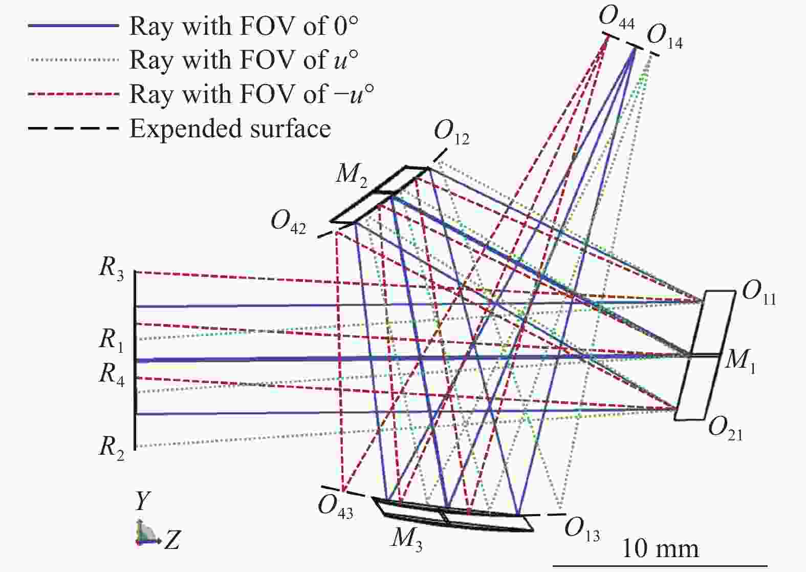
图 4 特征光线追迹示意图
Figure 4. Schematic diagram of characteristic ray tracing
通过对特征光线的追迹和定位建立离轴三反无遮拦判定条件,以辅助后续优化设计。当视场扩展至±u时,分别追迹最大视场边缘孔径光线R1、R2、R3、R4,并标记特征光线在各反射镜上的反射点坐标,各特征光线相关参数见表6,其中Px、Py分别为归一化光瞳坐标,Hx、Hy分别为归一化视场坐标。
表 6 特征光线参数
Table 6. Feature ray parameter
Pupil Field Coordinate (z, y) Px Py Hx Hy M1 M2 M3 Image R1 0 1 0 1 O11(z11, y11) O12(z12, y12) O13(z13, y13) O14(z14, y14) R2 0 −1 0 1 O21(z21, y21) O22(z22, y12) O23(z23, y23) O24(z24, y24) R3 0 1 0 −1 O31(z31, y31) O32(z32, y32) O33(z33, y33) O34(z34, y34) R4 0 −1 0 −1 O41(z41, y41) O42(z42, y42) O43(z43, y43) O44(z44, y44) 结合图4中特征光线与元件之间的相对位置关系,确定光学元件的结构限制条件如下:
$$ \left\{ {\begin{array}{*{20}{c}} {}&{\left| {\begin{array}{*{20}{c}} 1&{{z_{13}}}&{{y_{13}}} \\ 1&{{z_{14}}}&{{y_{14}}} \\ 1&{{z_{11}}}&{{y_{11}}} \end{array}} \right| < 0} \\ {}&{\left| {\begin{array}{*{20}{c}} 1&{{z_{13}}}&{{y_{13}}} \\ 1&{{z_{14}}}&{{y_{14}}} \\ 1&{{z_{21}}}&{{y_{21}}} \end{array}} \right| < 0} \end{array}} \right. $$ (13) $$ \left\{ {\begin{array}{*{20}{c}} {}&{\left| {\begin{array}{*{20}{c}} 1&{{z_{43}}}&{{y_{43}}} \\ 1&{{z_{44}}}&{{y_{44}}} \\ 1&{{z_{12}}}&{{y_{12}}} \end{array}} \right| > 0} \\ {}&{\dfrac{{{y_{11}} - {y_{42}}}}{{{z_{11}} - {z_{42}}}} < - \tan u} \end{array}} \right. $$ (14) $$ \left\{ {\begin{array}{*{20}{c}} {}&{\dfrac{{{y_{13}} - {y_{21}}}}{{{z_{13}} - {z_{21}}}} > \tan u} \\ {}&{\dfrac{{{y_{43}} - {y_{21}}}}{{{z_{43}} - {z_{21}}}} > \tan u} \end{array}} \right. $$ (15) 其中,不等式组(13)、(14)、(15)分别为针对M1、M2、M3的结构限制条件,满足以上不等式可保证视场为±u时,边缘光线不被遮拦。
离轴式结构破坏了光学系统的旋转对称特性,同轴系统设计中视场的采样方法不足以全面地评估成像质量,另外,考虑到后续将引入自由曲面,应保证足量的视场被采样以避免局部面形未被优化。在面形参数复杂的情况下,若直接将初始结构视场由0°提升至±3.8°并同时进行大量采样,会导致优化速度慢且效率低[10],故采用小视场逐步扩展优化的方法依次对x、y方向的视场点进行采样,如图5所示。

图 5 视场扩展示意图
Figure 5. Schematic diagram of expanding FOV
每一轮视场扩展后都需要进行光线是否被遮拦的判断,并在无遮拦的前提下对系统进行优化使其在当前视场下像质满足设计需求。设计及优化流程图如图6所示。

图 6 视场扩展优化流程图
Figure 6. Flow chart for expanding FOV optimization
以0.5°为步长扩展视场,首先判断结构是否对视场扩展后的光线造成遮拦。若光线没有被遮拦,则以扩展后视场为系统全视场更新评价函数;若光线被遮拦,则将表3中结构参数作为变量并以不等式组(13)~(15)为核心更新评价函数,优化结构参数,若优化后结构仍存在遮拦,则减小扩展步长。进而在无遮拦结构的基础上以提升像质为目标,优化椭球面二次项系数及自由曲面多项式系数等面形参数,并重复上述扩展视场及优化面形的过程直至视场及像质均符合设计指标需求。
-
优化后的系统光路由三片反射镜组成,如图7所示,其中主镜为离轴抛物面、次镜为椭球面基底的偶次非球面、三镜为椭球面基底的自由曲面,体积为26 mm×24 mm×10 mm,其厚度由通光口径决定。相较于潜望式长焦镜头,该设计在小型化、轻量化方面具备明显优势。同时,全反射面的设计无需考虑色差的校正且光能损耗更小。

图 7 优化后紧凑型长焦镜头
Figure 7. Layout of compact telephoto lens after optimization
该系统不存在色差,故以调制传递函数MTF、畸变及相对照度作为评估紧凑型长焦手机镜头成像质量的技术指标。
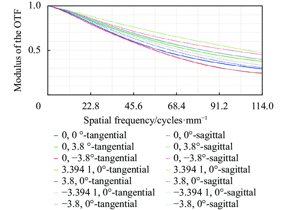
MTF反映光学系统除畸变外的其余像差对像质的综合影响,是一种客观全面的像质评价方法。该系统选用2/3 in、1200万像素EXR CMOS传感器,像元尺寸为2.2 μm×2.2 μm。目前,华为、小米等手机厂商均采用四像素合一技术,即将四个相邻的小尺寸像素合并为一个大尺寸像素,以达到提高画面纯净度、增强弱光拍摄能力的目的,故等效像元尺寸可视为4.4 μm×4.4 μm,MTF截止频率为114 lp/mm。图8所示为系统各视场下MTF曲线,在截止频率处各视场MTF均大于0.2。

图 8 调制传递函数曲线
Figure 8. MTF curves
±x和±y方向上的相对照度曲线与畸变曲线如图9所示。可以看出,相对照度曲线均高于95%,像面边缘无暗角,最大畸变位于全视场处,其值小于0.5%,满足设计需求[3]。

图 9 (a)相对照度曲线;(b)畸变曲线
Figure 9. (a) Curve of relative illumination; (b) Curve of distortion
图10所示为该镜头的成像效果仿真,由图可见,系统成像清晰,边缘视场相对照度略低于中心视场,但像面并不存在暗角,在像面边缘可以看出畸变对成像表现的影响微弱。综上所述,该紧凑型长焦镜头各项指标参数均符合手机镜头成像需求,且成像质量良好。与表1中潜望式长焦镜头参数相比,所设计的紧凑型长焦系统在满足成像质量的前提下,其设计参数与当前市场上潜望式长焦镜头指标相当,虽然F数略大,但有效焦距更长。

图 10 成像效果仿真。(a)物;(b)像
Figure 10. Simulation of imaging performance. (a) Object; (b) Image
-
文中提出了一种紧凑型长焦系统设计方案,基于圆锥曲面焦点共轭的光学特性构建初始结构光学模型,建立设计指标与结构参数、面形参数之间的对应关系,并采用自由曲面对初始结构进行优化以扩大视场、提升像质,完成了F数为5、等效焦距达196 mm、视场范围±3.8°的紧凑型长焦镜头设计,成像质量良好,各视场、各波段MTF在截止频率处均高于0.2,相对畸变小于0.5%且无色差,像面相对照度高于95%无暗角,为轻量化、小型化、紧凑型长焦镜头的设计提供了新的解决思路。
Design of compact telephoto mobile phone lens based on freeform surface (invited)
-
摘要: 针对长焦镜头小型化、轻量化的设计需求,基于离轴三反结构探索紧凑型长焦光学系统设计方案。利用圆锥曲面焦点共轭的光学特性,通过相邻反射面焦点重合的方式构造可对轴上点完善成像的初始结构,并在此基础上,通过追迹特征光线建立针对离轴三反结构的光线无遮拦判定条件,从小视场出发制定视场扩展与自由曲面面形的优化设计策略。以长焦手机镜头为例,设计了一款F数为5、等效焦距达196 mm、视场范围±3.8°的离轴三反式紧凑型长焦镜头。其尺寸为26 mm×24 mm×10 mm,仅由3个反射面构成,MTF优于0.2@114 lp/mm,畸变低于0.5%,相对照度高于95%,像面无暗角。该系统无遮拦,无色差,且相较于常规潜望式长焦镜头,在小型化、轻量化方面具备明显优势,为紧凑型长焦镜头设计提供了新的解决思路。Abstract:
Objective Telephoto lens is widely used in astronomy, space optics, aerial reconnaissance, security monitoring and other fields due to its ability to image distant objects. For devices with high requirement of miniaturization and lightweight, such as telephoto lens mounted on mobile phone, the majority solution is to use one or more prisms to fold the optical path to form a periscopic-type lens. Although this approach allows the element to be placed in an ultra-thin mobile terminal, it does not solve the lengthy, voluminous and weighty problem caused by the characteristics of telephoto lens. Instead, multiple prisms are added to the system as reflective elements, making the structure even bulkier. For the purpose of designing a compact and lightweight telephoto lens, this paper explores the solution of compact system design based on the structure of off-axis three-mirror imager. The initial structure is designed by utilizing the optical properties of conical surface to achieve ideal imaging of the on-axis object. Freeform surface is applied to extend field of view (FOV) to complete the design of a compact telephoto optical system. Methods Off-axis three-mirror imager has the advantages of lightness, compactness, non-chromatic, unobstructed aperture, high reflectiveness, and low optical energy loss for all wavelengths after being coated. A compact telephoto lens design method is proposed based on the off-axis three-mirror structure. Firstly, positive-negative-positive (PNP) power distribution was decided for the purpose of compactness. Unobscured PNP reflective imagers with different layouts of elements are listed (Fig.2). Then they are analysed and compared in terms of both compactness and imaging performance. After the structure type has been determined, parameters such as distance and angle can be calculated (Fig.3). Next, the optical properties of conical surfaces whose focal points conjugate between each other are used to calculate surface parameters such as conical coefficients and vertex radius of curvature to construct the initial structure (Fig.4), which can image on-axis object ideally. Taking telephoto lens applied to smartphone as an example, after calculating initial structural parameters with the above design method, the judgment condition that ray is obscured or not is established, and an optimized design strategy is developed to construct freeform surface, extend FOV (Fig.5) and optimize the system (Fig.6). The design of a compact telephoto lens is implemented and the feasibility of the design method is verified. Results and Discussions The result (Fig.7) is a compact telephoto lens with an F-number of 5, equivalent focal length of 196 mm and FOV of ±3.8°, consisting of only three reflective mirror and volume of 26 mm × 24 mm × 10 mm. The design results show that modulation transfer function (MTF) is greater than 0.2 at 114 lp/mm for all FOV (Fig.8), relative distortion is less than 0.5% (Fig.9) and displays good performance of imaging quality (Fig.10), meeting the imaging requirements of mobile phone lens. Our design is comparable to the current market indicators of periscopic-type telephoto lens in terms of design parameters. Although the F-number is slightly larger, effective focal length is longer, and it has obvious advantages in miniaturization and light weight. Conclusions In order to achieve a compact and lightweight telephoto lens design, this paper proposes a design method for a compact telephoto system based on optical characteristics of conical surface, combined with the off-axis three-mirror structure type. With the initial structure of off-axis three-mirror with ideal imaging at on-axis object, freeform surface is used to achieve a compact, lightweight, and high image quality telephoto system based on the unobstructed judgment condition and FOV expansion optimization strategy. The solution contains only three mirrors to fold ray path and compress volume, resulting in a lighter system with fewer lenses and less optical energy loss than a refractive telephoto imager, and an unrestricted wavelength band which means non-chromatic. Additionally, conical surface is used to calculate off-axis initial structure directly without aberrations at on-axis object, and subsequently controlling optimization process in combination with unobstruction judgement, avoiding the problem of aperture obstructed in the reflective telephoto. The result is a compact telephoto lens with an F-number of 5, an equivalent focal length of 196 mm and a field of view of ±3.8°, which meets the imaging requirements and has obvious advantages in terms of miniaturization and lightness compared to periscopic-type telephoto lens, providing a new solution to the design of compact telephoto lenses. -
Key words:
- optical design /
- telephoto lens /
- freeform surface /
- off-axis three-mirror
-
图 2 (a)~(d)正-负-正型离轴三反的4种结构;(e)~(f) 与(a)~(d)对应的圆锥曲面相对位置关系示意图
Figure 2. (a)-(d) 4 structures of unobscured positive-negative-positive (PNP) reflective imagers; (e)-(f) Relative positions of conic surfaces corresponding to (a)-(d)
图 9 (a)相对照度曲线;(b)畸变曲线
Figure 9. (a) Curve of relative illumination; (b) Curve of distortion
图 10 成像效果仿真。(a)物;(b)像
Figure 10. Simulation of imaging performance. (a) Object; (b) Image
表 1 手机搭载长焦镜头参数
Table 1. Parameters of telephoto lens on mobile phones
Year Brand Type F/# Equivalent focal length/mm 2019 Huawei P30 3.4 125 2022 Honor Magic4 Pro 3.5 95 2022 Samsung Galaxy S22 2.4 69 2022 Vivo X80 Pro 3.4 125 2022 OnePlus 10 Pro 2.4 77 2022 Xiaomi 12S Ultra 4.1 120  下载: 导出CSV
表 2 光学系统设计参数
Table 2. Design parameters of optical system
Parameter Value Aperture/mm 10 F-number 5 Equivalent focal length/mm 196 FOV/(°) ±3.8 Spectral bands/μm 0.38-0.78 Image plane size/mm2 6.6×8.8
下载: 导出CSV
表 3 初始结构参数
Table 3. Structural parameter of starting geometry
θi Value/(°) di Value/mm θ1 150 d1 14.72 θ2 120 d2 14.72 θ3 150 d3 17.74
下载: 导出CSV
表 4 光焦度分配
Table 4. Distribution of focal power for each surface
φ φ1 φ2 φ3 Value/mm−1 0.02 0.01 -0.017 0.18
下载: 导出CSV
表 5 初始面形参数
Table 5. Surface parameter of starting geometry
ri/mm di/mm ki M1 107.39 15.72 −1 M2 29.58 14.86 −0.3 M3 28.055 20.45 −0.17
下载: 导出CSV
表 6 特征光线参数
Table 6. Feature ray parameter
Pupil Field Coordinate (z, y) Px Py Hx Hy M1 M2 M3 Image R1 0 1 0 1 O11(z11, y11) O12(z12, y12) O13(z13, y13) O14(z14, y14) R2 0 −1 0 1 O21(z21, y21) O22(z22, y12) O23(z23, y23) O24(z24, y24) R3 0 1 0 −1 O31(z31, y31) O32(z32, y32) O33(z33, y33) O34(z34, y34) R4 0 −1 0 −1 O41(z41, y41) O42(z42, y42) O43(z43, y43) O44(z44, y44)
下载: 导出CSV
-
[1] Corbacho V V, Kuiper H, Gill E. Review on thermal and mechanical challenges in the development of deployable space optics [J]. Journal of Astronomical Telescopes, Instruments, and Systems, 2020, 6(1): 010902. doi: 10.1117/1.JATIS.6.1.010902 [2] 李旭阳, 倪栋伟, 杨明洋, 等. 基于自由曲面的大视场空间相机光学系统设计[J]. 光子学报, 2018, 47(9): 922003. doi: 10.3788/gzxb20184709.0922003. Li Xuyang, Ni Dongwei, Yang Mingyang, et al. Design of large field of view space camera optical system based on freeform surfaces [J]. Acta Optica Sinica, 2018, 47(9): 0922003. (in Chinese) doi: 10.3788/gzxb20184709.0922003 [3] Sun W, Tien C, Liu Y. Optical design for the lens depth of a periscope-type 3× zoom lens with 8-megapixel mobile phone [J]. Optical and Quantum Electronics, 2020, 52(3): 141. doi: 10.1007/s11082-020-2256-3 [4] 卢建龙, 叶海水, 牛亚军, 等. 长焦镜头, 摄像头模组及电子设备: 中国, 202110815848. X [P]. 2022-08-30. [5] Bauer A, Schiesser E M, Rolland J P. Starting geometry creation and design method for freeform optics [J]. Nature Communications, 2018, 9(1): 1756. doi: 10.1038/s41467-018-04186-9 [6] 梁子健, 杨甬英, 赵宏洋, 等. 非球面光学元件面型检测技术研究进展与最新应用[J]. 中国光学, 2022, 15(2): 161-186. doi: 10.37188/CO.2021-0143. Liang Zijian, Yang Yongying, Zhao Hongyang, et al. Advances in research and applications of optical aspheric surface metrology [J]. Chinese Optics, 2022, 15(2): 161-186. (in Chinese) doi: 10.37188/CO.2021-0143 [7] 许宁晏, 陈露, 黄静, 等. 自由曲面成像光学系统的初始结构设计方法[J]. 红外与激光工程, 2022, 51(2): 20210852. doi: 10.3788/IRLA20210852. Xu Ningyan, Chen Lu, Huang Jing, et al. Review of design methodology for starting-point of freeform surface imaging optical system [J]. Infrared and Laser Engineering, 2022, 51(2): 20210852. (in Chinese) doi: 10.3788/IRLA20210852 [8] 潘君骅, 李新南. 偏轴两镜系统的设计[J]. 光学学报, 1994, 14(8): 867-871. Pan Junhua, Li Xinnan. Design of a tilted two-mirror optical system [J]. Acta Optica Sinica, 1994, 14(8): 867-871. (in Chinese) [9] 林晶, 崔庆丰, 朱浩. 宽幅离轴三反光学系统研究[J]. 光学学报, 2013, 33(7): 0722002. doi: 10.3788/AOS201333.0722002 Lin Jing, Cui Qingfeng, Zhu Hao. Research of broad width off-axis three mirror optical system [J]. Acta Optica Sinica, 2013, 33(7): 0722002. (in Chinese) doi: 10.3788/AOS201333.0722002 [10] 姚艳霞, 袁群, 陈露, 等. 结合面型和视场优化策略的自由曲面设计方法[J]. 红外与激光工程, 2018, 47(10): 1018001-1018001(8). doi: 10.3788/IRLA201847.1018001. Yao Yanxia, Yuan Qun, Chen Lu, et al. Freeform surface design method combined with surface and field-of-view optimization [J]. Infrared and Laser Engineering, 2018, 47(10): 1018001. (in Chinese) doi: 10.3788/IRLA201847.1018001 -

 点击查看大图

计量
- 文章访问数: 148
- HTML全文浏览量: 32
- PDF下载量: 74
- 被引次数: 0

