


-
激光通信具有距离远、速率高、体积小、质量轻、功耗低的优点[1-2],所以近年来星间激光通信发展迅速,国内外相关单位已经开展了大量研究工作,研制了实验样机并在卫星上开展了演示实验。单摆镜式粗跟踪伺服转台是一种重要的激光通信机械转台,其采用一面可二维转动的伺服摆镜实现粗跟踪功能,该结构形式具有体积小、质量轻的优势[3]。为了减小摆镜的质量,保证其面形精度,其背部多采用中心支撑方案[4]。王桂冰等人针对空间遥感器摆镜,采用锥形后表面结构结合中心支撑方案,设计的摆镜组件包括摆镜、柔性支撑件以及背部支撑板。采用双层挠性结构在柔性支撑底面开六条相互交错的槽,来吸收温度变化时产生的变形[5]。王朋朋等人针对某型离轴三反光学系统的长条形反射镜采用的中心支撑方式,设计了一种柔性支撑结构,包括锥套、柔性元件、背板、过渡角等,柔性元件采用一种双轴圆弧柔性铰链结构,具有体积小、无机械摩擦、无间隙和高灵敏度传动的特点,可通过自身的变形来改善镜面由于热应力所造成的面形误差[6]。国内的研究均未见对大厚度平背形伺服摆镜支撑方式的相关报道。
针对某激光通信系统地面原理样机,系统采用相干通信体制,为了保证激光偏振态稳定伺服摆镜需镀制介质膜,介质膜厚度和应力较大容易破坏面形精度,为此,伺服摆镜必须采用平背形结构、正面和背部双面同时镀膜的方式保证摆镜正反两面受力对称,减小介质膜对面形精度的影响。由于摆镜的厚度和质量较大,且无法采用中心支撑,对摆镜采用周边支撑方案,对周边支撑的镜座和柔性支撑结构进行了参数化优化设计。系统要求摆镜组件在重力作用以及环境温度(23±5) ℃ 时,组件的一阶谐振频率超过300 Hz;最大面形误差RMS影响成像质量和通信耦合效率,通常要求平面镜RMS≤λ/40。文中通过摆镜形状尺寸优化、支撑方案的设计、柔性支撑结构的参数优化三个方面进行结构设计,并运用有限元方法对组件结构进行仿真分析,最后通过实验验证了组件结构满足设计指标要求。
-
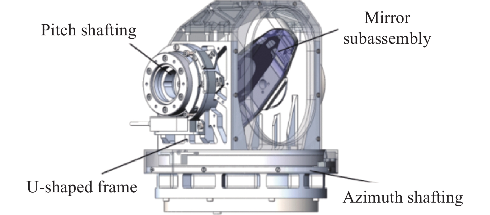
激光通信实现的前提是通信双向链路的建立以及收发视轴保持稳定的精确对准,所以需要良好的光束捕获、对准以及跟踪性能[7]。某星间激光通信系统地面原理样机中,由于需要的工作角度范围不大,为了减小可动部件的质量,降低系统的质量,粗跟踪转台采用单摆镜式结构,总体结构与布局如图1所示。转台主要由方位组件、U形架、俯仰组件和摆镜组件组成,可二维转动摆镜对光轴角度进行调整,实现通信激光的对准捕获和跟踪。

图 1 单摆镜式伺服转台总体布局
Figure 1. General layout of single pendulum mirror servo turntable
为了保证摆镜结构刚度,减小质量,传统伺服摆镜背部截面多采用非平面结构,常见截面形状有锥形、弯月形、单拱形等。但在文中的激光通信系统中,需要将摆镜正反两面镀制保偏介质膜[8-9],保证镜体等厚,两侧双面受力均匀。系统通过热控设计后,保证摆镜的工作环境温度为±5 ℃。
-
系统有效通光口径为Ф75 mm,摆镜工作角度在60°时长轴最长,留取设计余量后,摆镜有效形状设计为长轴154 mm、短轴79 mm的椭圆,径厚比为8∶1,厚度为20 mm。摆镜材料选用微晶玻璃,加工后面形误差PV优于λ/7,RMS优于λ/50;为减小系统质量,支撑镜座选用钛合金材料,摆镜组件材料性能参数如表1所示。
表 1 摆镜组件材料性能参数
Table 1. Material properties of reflector components
Part Material E/GPa ρ/g·cm−3 α/℃ k/W∙(M∙K)−3 ν Mirror Zerodur 91 2.53 0.05 1.64 0.24 Support TC4 109 4.44 8.9 7.8 0.31 为了方便在摆镜周围设计粘接点位置,同时为椭圆形摆镜的光学有效区域建立缓冲区,减小粘接点对摆镜面形的影响,故将摆镜设计为八边形结构,每条斜边与椭圆相切,在四条斜边上设计粘接点,每条斜边设计两个粘接点,摆镜平面形状如图2所示。

图 2 摆镜平面形状
Figure 2. Plane shape of pendulum mirror
-
设计时,粘接点处与有效椭圆区域间的镜体可以作为缓冲区,有效减小应力对有效区域内面形的影响。粘接点位置决定了各点应力和缓冲区域的大小,为此有必要对摆镜的形状、切点位置和粘接点位置进行优化。以切点1、粘接点1和粘接点2为例,如图2所示,角度α决定了切点1的位置以及摆镜形状,粘接点与切点的距离L1和L2确定了粘接点位置。由于优化参数较多,采用正交实验法对参数α、L1和L2进行优化[10]。为了简化优化难度,约束条件设定为在重力作用下摆镜椭圆内有效区域面形最优。
结合结构尺寸且保证粘接点位置的合理性,确定α≥108°,L1>22 mm,L2>12 mm,各参数取值如表2所示。采用四水平三因素正交实验法,用16种组合完成全部的64种参数组合的参数优化方案,具体参数设置如表3所示。评价指标为标准地球重力作用下有效椭圆区域内面形精度RMS值,由V表示。
表 2 摆镜粘接点位置参数因素水平表
Table 2. Parameter level table of the position of the bonding point of the pendulum mirror
Level Factors α/(°) L1 /mm L2 /mm 1 106 20 14 2 107 21 15 3 108 22 16 4 109 23 17 表 3 摆镜粘接点位置参数正交实验方案
Table 3. Orthogonal test scheme of the position of the bonding point of the pendulum mirror
No. α/(°) L1/mm L2 /mm V/nm 1 106 20 14 0.861 2 106 21 15 0.804 3 106 22 16 0.877 4 106 23 17 1.067 5 107 20 15 0.851 6 107 21 14 0.660 7 107 22 17 1.070 8 107 23 16 0.863 9 108 20 16 0.895 10 108 21 17 0.905 11 108 22 14 1.059 12 108 23 15 1.053 13 109 20 17 1.117 14 109 21 16 1.033 15 109 22 14 1.198 16 109 23 15 1.289 各因素的极差如表4所示,N1、N2、N3、N4分别表示角度α、粘接点1到切点距离L1、粘接点2到切点的距离L2这三个因素在四个水平条件下摆镜面形RMS值的平均值。R为三个因素全水平平均值中的极差值,极差值越大表示该因素下所选水平对面形精度值的影响越大。
表 4 摆镜粘接点位置参数因素极差分析
Table 4. Range analysis of factors of the position of the bonding point of the pendulum mirror
Factors A B C α/(°) L1/mm L2/mm N1 0.902 0.931 0.945 N2 0.861 0.851 0.999 N3 0.978 1.051 0.917 N4 1.159 1.068 1.039 R 0.298 0.217 0.122 通过极差分析可得出各因素对摆镜面形的影响顺序依次为:角度α>粘接点2到切点的距离L2>粘接点1到切点距离L1。通过分析,在标准地球重力的工况下最佳组合参数为A2B2C3组合,即α=107°,L1=21 mm,L2=16 mm。
对优化后的摆镜在轴向标准地球重力作用下进行静力学分析。经过Sigfit面形拟合后,摆镜面形精度RMS值为0.784 nm,面形云图如图3所示。

图 3 标准地球重力下摆镜面形云图
Figure 3. Pendulum mirror-shaped cloud map of standard Earth gravity
-
常见的摆镜支撑结构有背部支撑、侧面支撑和周边支撑[11-12]三种方式,这三种方式都可以引入柔性结构,降低热应力的影响,但是应用场合有所不同。文中设计的大厚度平背形伺服摆镜,由于镜体背部截面为平背形,镜体等厚且无法采用轻量化设计,常见的背部支撑方案并不适用,故采用周边柔性支撑方案[13]。摆镜组件在设计时不仅要充分保证摆镜面形精度,还要保证组件的谐振频率。因此,需对柔性支撑参数进行优化设计,满足面形和谐振频率的要求。
-
柔性支撑多采用切口铰链结构,通过对粘接点处机械结构进行切口处理形成铰链结构,达到降低结构刚度、减小结构变形产生的应力的作用[14]。
摆镜镜座如图4所示,采用四周封闭的结构形式增大支撑镜座结构的刚度,在摆镜粘接点对应的位置设计柔性铰链和粘接结构[15]。在结构变形时,每个粘接点会在三个方向上产生应力,以粘接点1为例,坐标系X轴垂直于粘接面,Y轴平行于粘接面,Z轴满足右手定则。考虑到摆镜在厚度方向上的变形尺寸远小于另外两个方向,因此忽略Z轴方向的影响,柔性铰链重点考虑X轴和Y轴方向的影响。

图 4 柔性铰链结构示意图。(a)铰链1示意图;(b)铰链2示意图
Figure 4. Schematic diagram of flexible hinge structure. (a) Schematic diagram of hinge 1; (b) Schematic diagram of hinge 2
为了抑制X轴和Y轴方向应力的影响,每个粘接点的柔性支撑结构由两组铰链构成,通过开槽提高结构柔度,减小结构变形产生的应力,同时使最大应力点远离粘接点,减小对摆镜面形的影响。某一粘接点处柔性铰链1结构如图4(a)所示,铰链1主要抵消X轴方向的应力;柔性铰链2结构如图4(b)所示,铰链2主要抵消Y轴方向应力。镜座在支撑点处设计有注胶点和粘接面,采用硫化硅橡胶粘接,粘接点处设计凸台,方便保证粘接点位置尺寸精度,同时便于柔性铰链的设计与加工。
-
由于摆镜镜座柔性支撑结构参数较多,采用正交实验法对结构参数进行优化。以粘接点1为例,柔性支撑的主要结构参数有:铰链1长度a,铰链1宽度h,铰链1高度b,铰链2长度r,铰链2宽度s,铰链2高度t,各参数如图5所示。

图 5 柔性铰链结构主要参数示意图
Figure 5. Schematic diagram of the main parameters of the flexible hinge structure
在实际结构设计中,根据结构尺寸以及加工工艺,确定a≤16 mm,h≥2.4 mm,b≥16 mm,r≥2 mm,s≥2.4 mm,t≥8 mm,各参数的取值如表5所示。采用五水平六因素正交实验法,根据L25(56)标准正交表,用25种组合完成全部15625种参数组合的柔性支撑结构的参数优化方案,具体参数设置如表6所示。评价指标为5 ℃温升作用下有效椭圆区域内面形精度RMS值,均由P表示。
表 5 柔性支撑结构参数因素水平表
Table 5. Parameter level of flexible support structure
Level Factors a/mm h/mm b/mm r/mm s/mm t/mm 1 12 2.4 16.5 2 2.4 8 2 13 2.8 17 2.5 2.8 9 3 14 3.2 17.5 3 3.2 10 4 15 3.6 18 3.5 3.6 11 5 16 4 18.5 4 4 12 表 6 柔性支撑结构参数正交实验方案
Table 6. Orthogonal test scheme of flexible support structure
No. a/mm h/mm b/mm r/mm s/mm t/mm P/nm 1 12 2.4 16.5 2 2.4 8 24.03 2 12 2.8 17 2.5 2.8 9 33.04 3 12 3.2 17.5 3 3.2 10 44.58 4 12 3.6 18 3.5 3.6 11 59.03 5 12 4 18.5 4 4 12 70.99 6 13 2.4 17 3 3.6 12 41.27 7 13 2.8 17.5 3.5 4 8 38.35 8 13 3.2 18 4 2.4 9 22.70 9 13 3.6 18.5 2 2.8 10 33.63 10 13 4 16.5 2.5 3.2 11 47.07 11 14 2.4 17.5 4 2.8 11 20.58 12 14 2.8 18 2 3.2 12 30.08 13 14 3.2 18.5 2.5 3.6 8 25.17 14 14 3.6 16.5 3 4 9 44.48 15 14 4 17 3.5 2.4 10 24.02 16 15 2.4 18 2.5 4 10 29.49 17 15 2.8 18.5 3 2.4 11 16.25 18 15 3.2 16.5 3.5 2.8 12 22.05 19 15 3.6 17 4 3.2 8 16.60 20 15 4 17.5 2 3.6 9 30.25 21 16 2.4 18.5 4 3.2 9 12.01 22 16 2.8 16.5 2 3.6 10 20.19 23 16 3.2 17 2.5 4 11 32.46 24 16 3.6 17.5 3 2.4 12 14.84 25 16 4 18 3.5 2.8 8 10.09 各因素的极差如表7所示,N1、N2、N3、N4、N5分别表示柔性支撑结构铰链1长度a、铰链1宽度h、铰链1高度b、铰链2长度r、铰链2宽度s以及铰链2高度t这六个因素在五个水平条件下摆镜面形RMS值的平均值。R为因素全水平平均值中的极差值,极差值越大表示该因素下所选水平对面形精度值的影响越大。
表 7 柔性支撑结构参数因素极差分析
Table 7. Range analysis of factors of flexible support structure
Factors A B C D E F a/mm h/mm b/mm r/mm s/mm t/mm N1 46.33 25.48 31.64 27.70 20.37 22.85 N2 36.60 27.58 29.48 33.45 23.88 28.57 N3 28.87 29.27 29.72 32.28 30.07 30.38 N4 22.93 33.72 30.28 30.71 35.18 35.08 N5 17.92 36.48 31.61 28.58 43.15 35.85 R 28.41 11 2.16 5.75 22.78 13 通过极差分析可得出各因素对摆镜面形的影响顺序依次为:铰链1长度a>铰链2宽度s>铰链2高度t>铰链1宽度h>铰链2长度r>铰链1高度b。根据四个水平的面形平均值可见,在5 ℃温升工况下最佳组合参数为A5B1C2D1E1F1,即a=16 mm,h=2.4 mm,b=17 mm,r=2 mm,s=2.4 mm,t=8 mm。
-
为了验证摆镜组件的动态刚度,对模型进行模态分析,边界条件定义为摆镜镜座与转台连接位置六自由度全约束,与实际安装工况一致。
摆镜组件的前六阶模态分析结果如表8所示。有限元分析结果表明,摆镜组件一阶频率为446.66 Hz,动态刚度较高,满足设计指标要求的元件模态频率大于300 Hz。一阶阵型为摆镜沿x轴平移,结果云图如图6所示,因此摆镜组件完全满足结构动态刚度要求。
表 8 摆镜组件模态分析结果
Table 8. Results of modal analysis of pendulum mirror assembly
Order Fz/Hz Mode of vibration 1 446.66 Pendulum mirror translates along the x-axis 2 1137.7 Pendulum mirror translates along the y-axis 3 1248.2 Pendulum mirror translates along the z-axis 4 1282.7 Pendulum mirror rotates around x-axis 5 1361.1 Pendulum mirror rotates around z-axis 6 2134.1 Pendulum mirror rotates around y-axis 
图 6 摆镜组件一阶模态云图
Figure 6. First-order modal cloud of the pendulum mirror assembly
-
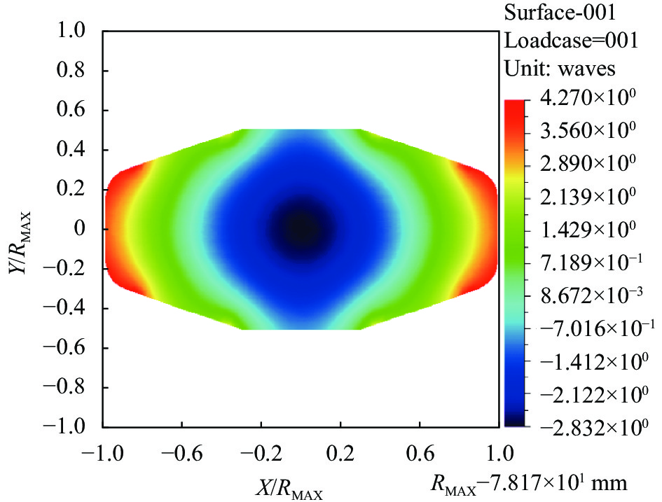
对摆镜组件在X、Y、Z三个方向施加标准地球重力载荷以及5 ℃温升(降)耦合的工况下分析结果如表9所示,面形云图如图7所示。
表 9 5 ℃温升(降)和标准地球重力作用下摆镜面形精度分析结果(单位:nm)
Table 9. Analysis results of 5 ℃ temperature rise (fall) and standard earth gravity under the pendulum mirror surface shape accuracy (Unit: nm)
Load case direction Temperature rise Temperature reduction PV RMS PV RMS X λ/16.34 λ/92.13 λ/16.75 λ/95.13 Y λ/17.23 λ/94.97 λ/17.47 λ/95.43 Z λ/16.55 λ/83.28 λ/19.88 λ/101 从表9的分析结果可见,摆镜组件在标准地球重力载荷以及5 ℃均匀温升、温降的共同作用下,最大面形误差PV值为λ/16.34,RMS值为λ/83.28。摆镜的最终面形精度由摆镜加工后面形与支撑机构产生的面形误差共同决定。为评价支撑后摆镜面形,整体面形误差PV值按摆镜加工面形误差PV值与支撑结构产生面形误差PV值叠加计算,RMS值按两者的均方根值计算。经计算后,采用该支撑结构后摆镜的最终面形误差PV值为λ/5,RMS值为λ/42.87,满足面形精度要求。
$$ \begin{split} & \qquad \qquad {{PV}} = \lambda /7 + \lambda /16.34 = \lambda /5 \\ & {{RMS}} = \sqrt {{{\left( {\lambda /50} \right)}^2} + {{\left( {\lambda /83.28} \right)}^2}} = \lambda /42.87 \end{split} $$ (1) 
图 7 摆镜5 ℃温升(降)和标准地球重力作用下镜面面形云图
Figure 7. Pendulum mirror 5 ℃ temperature rise (fall) and standard earth gravity effect of the mirror surface surface shape cloud map
-
摆镜镜座实物如图8(a)所示,摆镜组件实物如图8(b)所示,整机装配图如图8(c)所示。使用ZYGO激光干涉仪在(23±5) ℃温度范围内对摆镜组件进行面形检测,检测系统如图9所示。

图 8 摆镜组件实物图与整机装配图
Figure 8. Physical drawing of the pendulum mirror assembly and the whole machine assembly diagram

图 9 摆镜组件检测系统
Figure 9. System for pendulum mirror assembly inspection
检测结果如表10所示,不同温度下摆镜面形结果如图10所示。经检测,摆镜组件在(23±5) ℃温度范围的面形误差RMS值最大为λ/43.28,满足指标要求,证明该周边柔性支撑结构能够保证摆镜组件具有良好的热稳定性。
表 10 摆镜组件面形检测结果(单位:nm)
Table 10. Results of pendulum mirror assembly face shape test (Unit: nm)
Temperature/°C PV RMS 15 λ/5.41 λ/45.34 20 λ/5.49 λ/45.71 25 λ/5.10 λ/43.28 
图 10 不同温度下摆镜组件面形的检测结果
Figure 10. Results of pendulum mirror assembly surface shape testing at different temperatures
-
通过正弦扫频实验验证摆镜柔性支撑的结构刚度。在摆镜镜面安装传感器,测该点的响应曲线如图11所示。由响应曲线可知,摆镜组件Z向一阶谐振频率为458.3 Hz,与模态分析结果的相对误差为2.5%,分析结果相对准确。

图 11 Z向正弦扫频实验曲线
Figure 11. Sweep sine response curve under Z vibration
-
为保证大厚度平背形伺服摆镜系统在恶劣环境下的动态刚度以及面形精度,提出了一种周边柔性支撑结构方案。对摆镜形状、粘接点位置以及周边柔性支撑结构进行了参数化设计,并根据正交实验法对其参数进行优化,得到了满足设计要求的周边柔性支撑结构。经过有限元分析,摆镜组件基频为446.66 Hz,满足设计指标要求的元件模态频率大于300 Hz;在(23±5) ℃温度范围内,摆镜面形PV值为λ/5,RMS值为λ/42.87,优于λ/40的指标要求。使用ZYGO激光干涉仪对摆镜在不同温度下进行面形检测,实验结果表明,摆镜面形RMS值优于λ/40的设计值。因此,对摆镜形状、粘接点位置以及周边柔性支撑结构的参数化设计使摆镜组件的结构刚度和热稳定性满足了系统的设计要求。
Laser communication flat back servo pendulum mirror support structure optimization design
-
摘要: 为了保证平背伺服摆镜的镜面精度和支撑刚度,设计了一种周边柔性支撑的方案,通过对摆镜与镜座粘接处机械结构进行切口处理形成铰链结构,降低结构刚度,减小结构变形产生应力的影响。由于摆镜形状、粘接点位置、柔性支撑结构参数较多,并且相互耦合,首先采用正交实验法对摆镜主要参数进行分析与优化,确定摆镜形状尺寸参数和粘接点位置,随后优化设计摆镜柔性支撑结构。仿真分析和实验表明,采用该周边柔性支撑后,摆镜组件一阶频率为446.66 Hz,在±5 ℃温升(温降)和标准地球重力共同作用下,最大面形误差RMS为λ/42.87,能够满足动、静态刚度和热尺寸稳定性要求。随后使用 ZYGO 干涉仪在 (23±5) ℃ 温度范围内对加工装配后的摆镜面形进行检测,结果表明,摆镜面形PV值优于λ/5.1,RMS优于λ/43.28,满足 RMS≤λ/40的指标要求。实验结果表明,柔性支撑参数设计可靠,满足使用要求。Abstract:
Objective For a laser communication system ground principle prototype, the system uses coherent high-speed communication system, communication laser is polarized light, the optical system needs to be coated with dielectric film to ensure the stability of the polarization state. Affected by the thickness of the dielectric film and the coating process, the dielectric film has a large impact on the precision of the surface shape of the pendulum mirror, and it is very easy to cause the deterioration of the shape behind the coating. Therefore, the servo pendulum mirror is designed as a flat back structure to ensure the symmetry of the front and back sides of the pendulum mirror, and the front and back sides are coated simultaneously to reduce the influence of the dielectric film on the surface shape accuracy of the pendulum mirror. For the above reasons, the servo pendulum mirror is thicker, heavier and not easy to use the central support solution, so the peripheral flexible support structure is used. Methods In order to ensure the mirror precision and support stiffness of the pendulum mirror, a peripheral support scheme is designed, and according to the flexible support design theory, a peripheral flexible support structure is proposed to reduce the structural stiffness and reduce the stress generated by the structural deformation by forming a hinge structure through notching the mechanical structure at the bonding of the pendulum mirror and the mirror base. Since the shape of the pendulum mirror, the location of the bonding point and the flexible support structure have many parameters and are coupled with each other, the main parameters of the pendulum mirror are first analyzed and optimized by the orthogonal experiment method to determine the shape and size of the pendulum mirror and the location of the bonding point, and then the flexible support structure of the pendulum mirror is optimized. Results and Discussions It can be seen that the maximum surface shape error PV value of the pendulum mirror assembly is λ/16.34 and RMS value is λ/83.28 under the combined effect of standard earth gravity load and 5 ℃ uniform temperature rise and temperature drop (Tab.9). value is λ/5, and the RMS value is λ/42.87 to meet the surface accuracy requirement. The maximum RMS value of the surface shape error of the pendulum mirror assembly in the temperature range of (23±5) ℃ is λ/43.28 (Tab.10), which meets the requirement of the index, proving that the flexible support structure around the pendulum mirror assembly can ensure good thermal stability. Conclusions In order to ensure the dynamic stiffness and face shape accuracy of the large-thickness flat-backed servo pendulum mirror system under the harsh environment, a peripheral flexible support structure scheme is proposed. The shape of the pendulum mirror, the position of the bonding point and the peripheral flexible support structure are designed parametrically, and the parameters are optimized according to the orthogonal experiment method to obtain a peripheral flexible support structure that meets the design requirements. After the finite element analysis, the fundamental frequency of the pendulum mirror assembly is 446.66 Hz (Fig.6), which meets the design index requirement of component mode frequency greater than 300 Hz; the PV value of the pendulum mirror surface shape is λ/5 and the RMS value is λ/42.87 in the temperature range of (23±5) ℃ (Tab.9), which is better than the index requirement of λ/40. The surface shape of the pendulum mirror was examined at different temperatures using ZYGO laser interferometer (Fig.10), and the test results showed that the RMS value of the surface shape of the pendulum mirror was better than the design value of λ/40. Therefore, the parametric design of the pendulum mirror shape, bonding point location and the surrounding flexible support structure make the structural stiffness and thermal stability of the pendulum mirror assembly meet the design requirements of the system. -
Key words:
- laser communication /
- flexible support /
- orthogonal optimization /
- peripheral support /
- pendulum mirror
-
图 3 标准地球重力下摆镜面形云图
Figure 3. Pendulum mirror-shaped cloud map of standard Earth gravity
图 4 柔性铰链结构示意图。(a)铰链1示意图;(b)铰链2示意图
Figure 4. Schematic diagram of flexible hinge structure. (a) Schematic diagram of hinge 1; (b) Schematic diagram of hinge 2
图 5 柔性铰链结构主要参数示意图
Figure 5. Schematic diagram of the main parameters of the flexible hinge structure
图 7 摆镜5 ℃温升(降)和标准地球重力作用下镜面面形云图
Figure 7. Pendulum mirror 5 ℃ temperature rise (fall) and standard earth gravity effect of the mirror surface surface shape cloud map
图 8 摆镜组件实物图与整机装配图
Figure 8. Physical drawing of the pendulum mirror assembly and the whole machine assembly diagram
图 10 不同温度下摆镜组件面形的检测结果
Figure 10. Results of pendulum mirror assembly surface shape testing at different temperatures
表 1 摆镜组件材料性能参数
Table 1. Material properties of reflector components
Part Material E/GPa ρ/g·cm−3 α/℃ k/W∙(M∙K)−3 ν Mirror Zerodur 91 2.53 0.05 1.64 0.24 Support TC4 109 4.44 8.9 7.8 0.31  下载: 导出CSV
表 2 摆镜粘接点位置参数因素水平表
Table 2. Parameter level table of the position of the bonding point of the pendulum mirror
Level Factors α/(°) L1 /mm L2 /mm 1 106 20 14 2 107 21 15 3 108 22 16 4 109 23 17
下载: 导出CSV
表 3 摆镜粘接点位置参数正交实验方案
Table 3. Orthogonal test scheme of the position of the bonding point of the pendulum mirror
No. α/(°) L1/mm L2 /mm V/nm 1 106 20 14 0.861 2 106 21 15 0.804 3 106 22 16 0.877 4 106 23 17 1.067 5 107 20 15 0.851 6 107 21 14 0.660 7 107 22 17 1.070 8 107 23 16 0.863 9 108 20 16 0.895 10 108 21 17 0.905 11 108 22 14 1.059 12 108 23 15 1.053 13 109 20 17 1.117 14 109 21 16 1.033 15 109 22 14 1.198 16 109 23 15 1.289
下载: 导出CSV
表 4 摆镜粘接点位置参数因素极差分析
Table 4. Range analysis of factors of the position of the bonding point of the pendulum mirror
Factors A B C α/(°) L1/mm L2/mm N1 0.902 0.931 0.945 N2 0.861 0.851 0.999 N3 0.978 1.051 0.917 N4 1.159 1.068 1.039 R 0.298 0.217 0.122
下载: 导出CSV
表 5 柔性支撑结构参数因素水平表
Table 5. Parameter level of flexible support structure
Level Factors a/mm h/mm b/mm r/mm s/mm t/mm 1 12 2.4 16.5 2 2.4 8 2 13 2.8 17 2.5 2.8 9 3 14 3.2 17.5 3 3.2 10 4 15 3.6 18 3.5 3.6 11 5 16 4 18.5 4 4 12
下载: 导出CSV
表 6 柔性支撑结构参数正交实验方案
Table 6. Orthogonal test scheme of flexible support structure
No. a/mm h/mm b/mm r/mm s/mm t/mm P/nm 1 12 2.4 16.5 2 2.4 8 24.03 2 12 2.8 17 2.5 2.8 9 33.04 3 12 3.2 17.5 3 3.2 10 44.58 4 12 3.6 18 3.5 3.6 11 59.03 5 12 4 18.5 4 4 12 70.99 6 13 2.4 17 3 3.6 12 41.27 7 13 2.8 17.5 3.5 4 8 38.35 8 13 3.2 18 4 2.4 9 22.70 9 13 3.6 18.5 2 2.8 10 33.63 10 13 4 16.5 2.5 3.2 11 47.07 11 14 2.4 17.5 4 2.8 11 20.58 12 14 2.8 18 2 3.2 12 30.08 13 14 3.2 18.5 2.5 3.6 8 25.17 14 14 3.6 16.5 3 4 9 44.48 15 14 4 17 3.5 2.4 10 24.02 16 15 2.4 18 2.5 4 10 29.49 17 15 2.8 18.5 3 2.4 11 16.25 18 15 3.2 16.5 3.5 2.8 12 22.05 19 15 3.6 17 4 3.2 8 16.60 20 15 4 17.5 2 3.6 9 30.25 21 16 2.4 18.5 4 3.2 9 12.01 22 16 2.8 16.5 2 3.6 10 20.19 23 16 3.2 17 2.5 4 11 32.46 24 16 3.6 17.5 3 2.4 12 14.84 25 16 4 18 3.5 2.8 8 10.09
下载: 导出CSV
表 7 柔性支撑结构参数因素极差分析
Table 7. Range analysis of factors of flexible support structure
Factors A B C D E F a/mm h/mm b/mm r/mm s/mm t/mm N1 46.33 25.48 31.64 27.70 20.37 22.85 N2 36.60 27.58 29.48 33.45 23.88 28.57 N3 28.87 29.27 29.72 32.28 30.07 30.38 N4 22.93 33.72 30.28 30.71 35.18 35.08 N5 17.92 36.48 31.61 28.58 43.15 35.85 R 28.41 11 2.16 5.75 22.78 13
下载: 导出CSV
表 8 摆镜组件模态分析结果
Table 8. Results of modal analysis of pendulum mirror assembly
Order Fz/Hz Mode of vibration 1 446.66 Pendulum mirror translates along the x-axis 2 1137.7 Pendulum mirror translates along the y-axis 3 1248.2 Pendulum mirror translates along the z-axis 4 1282.7 Pendulum mirror rotates around x-axis 5 1361.1 Pendulum mirror rotates around z-axis 6 2134.1 Pendulum mirror rotates around y-axis
下载: 导出CSV
表 9 5 ℃温升(降)和标准地球重力作用下摆镜面形精度分析结果(单位:nm)
Table 9. Analysis results of 5 ℃ temperature rise (fall) and standard earth gravity under the pendulum mirror surface shape accuracy (Unit: nm)
Load case direction Temperature rise Temperature reduction PV RMS PV RMS X λ/16.34 λ/92.13 λ/16.75 λ/95.13 Y λ/17.23 λ/94.97 λ/17.47 λ/95.43 Z λ/16.55 λ/83.28 λ/19.88 λ/101
下载: 导出CSV
表 10 摆镜组件面形检测结果(单位:nm)
Table 10. Results of pendulum mirror assembly face shape test (Unit: nm)
Temperature/°C PV RMS 15 λ/5.41 λ/45.34 20 λ/5.49 λ/45.71 25 λ/5.10 λ/43.28
下载: 导出CSV
-
[1] 姜会林, 佟首峰. 空间激光通信技术与系统[M]. 北京: 高等教育出社, 2010. [2] 高铎瑞, 李天伦, 孙悦, 等. 空间激光通信最新进展与发展趋势[J]. 中国光学, 2018, 11(06): 901-913. doi: 10.3788/co.20181106.0901 Gao Duorui, Li Tianlun, Sun Yue, et al. Latest developments and trends of space laser communication [J]. Chinese Optics, 2018, 11(6): 901-913. (in Chinese) doi: 10.3788/co.20181106.0901 [3] 陈祥, 呼新荣, 张建华, 等. 摆镜式激光通信终端光束指向与粗跟踪特性[J]. 红外与激光工程, 2021, 50(12): 1-10. Chen Xiang, Hu Xinrong, Zhang Jianhua, et al. Beam pointing and coarse tracking characteristics of Tip-Tilt mirror type laser communication terminal [J]. Infrared and Laser Engineering, 2021, 50(12): 20210146. (in Chinese) [4] 汪奎, 辛宏伟, 徐宏, 等. 空间相机快速反射镜的结构轻量化设计[J]. 红外与激光工程, 2019, 48(04): 177-183. Wang Kui, Xin Hongwei, Xu Hong, et al. Lightweight design of fast steering mirror for space cameras [J]. Infrared and Laser Engineering, 2019, 48(4): 0418001. (in Chinese) [5] 李小明, 王桂冰, 张立中, 等. 单反式光端机反射镜柔性支撑参数化设计与试验[J]. 红外与激光工程, 2020, 49(04): 214-220. Li Xiaoming, Wang Guibing, Zhang Lizhong, et al. Parametric design and test of flexible support for mirror of single trans optical terminal [J]. Infrared and Laser Engineering, 2020, 49(4): 0414003. (in Chinese) [6] 王朋朋, 辛宏伟, 朱俊青, 等. 轻质长条形反射镜结构优化设计[J]. 光电工程, 2020, 47(08): 101-107. Wang Pengpeng, Xin Hongwei, Zhu Junqing, et al. Structural optimization design of lightweight rectangular reflective mirror [J]. Opto-Electronic Engineering, 2020, 47(8): 101-107. (in Chinese) [7] 郑运强, 刘欢, 孟佳成, 等. 空基激光通信研究进展和趋势以及关键技术[J]. 红外与激光工程, 2022, 51(06): 397-409. Zheng Yunqiang, Liu Huan, Meng Jiacheng, et al. Development status, trend and key technologies of air-based laser communication [J]. Infrared and Laser Engineering, 2022, 51(6): 20210475. (in Chinese) [8] 叶紫晴, 丁宸聪, 周海军. 卫星相干激光通信系统与技术发展[J]. 电讯技术, 2022, 62(04): 547-552. doi: 10.3969/j.issn.1001-893x.2022.04.020 Ye Ziqing, Ding Chencong, Zhou Haijun. Satellite coherent laser communication system and technical progress [J]. Telecommunication Engineering, 2022, 62(4): 547-552. (in Chinese) doi: 10.3969/j.issn.1001-893x.2022.04.020 [9] 李响, 张立中, 李小明, 等. 多节点激光通信天线紧凑型摆镜组件设计[J]. 光学学报, 2017, 37(09): 59-65. Li Xiang, Zhang Lizhong, Li Xiaoming, et al. Design of compact tip-tilt mirror assembly in multi-node laser communication antennas [J]. Acta Optica Sinica, 2017, 37(9): 0906003. (in Chinese) [10] 任禄泉. 实验的优化设计与分析[M]. 北京: 高等教育出版社, 2003. [11] Tan Jinguo, He Xin, Fu Liangliang. Support technique in centre of minitype reflector [J]. Infrared and Laser Engineering, 2010, 39(6): 1070-1074. (in Chinese) [12] 凤良杰, 成鹏飞, 王炜. Φ450 mm口径空间天文相机轻量化碳化硅主反射镜组件设计[J]. 红外与激光工程, 2021, 50(02): 191-197. Feng Liangjie, Cheng Pengfei, Wang Wei. Design of Φ450 mm light-weighted SiC mirror subsystem in space-based astronomy telescope [J]. Infrared and Laser Engineering, 2021, 50(2): 20200175. (in Chinese) [13] 李晟, 范斌, 王伟刚, 等. 深低温SiC空间反射镜背部与侧面支撑结构对比[J]. 红外与激光工程, 2020, 49(02): 268-277. Li Sheng, Fan Bin, Wang Weigang, et al. Comparison of back supporting structure and side supporting structure of space mirror manufactured by silicon carbide in cryogenic environment [J]. Infrared and Laser Engineering, 2020, 49(2): 0214003. (in Chinese) [14] 李宗轩, 张昌昊, 张德福, 等. 1.8 m空间长条反射镜柔性支撑技术研究[J]. 中国光学(中英文), 2022, 15(05): 1079-1091. Li Zongxuan, Zhang Changhao, Zhang Defu, et al. Flexural mounting technology of a 1.8 m space-borne rectangular mirror [J]. Chinese Optics, 2022, 15(5): 1079-1091. (in Chinese) [15] 刘小涵, 李双成, 李美萱, 等. 离轴三反光学系统主三反射镜支撑结构设计[J]. 红外与激光工程, 2021, 50(08): 251-259. Liu Xiaohan, Li Shuangcheng, Li Meixuan, et al. Supporting structure design for primary and tertiary mirror of off-axis TMA system [J]. Infrared and Laser Engineering, 2021, 50(8): 20210025. (in Chinese) -

 点击查看大图
计量
- 文章访问数: 75
- HTML全文浏览量: 10
- PDF下载量: 19
- 被引次数: 0

