


-
衍射光栅广泛应用于超高精密位移测量系统[1]、仪器校准[2]等领域,但普通的衍射光栅不具备可溯源性,而溯源链的缺失会导致纳米测量仪器的测量准确性、一致性和可比性降低。利用原子光刻技术制备的自溯源型光栅[3-5],与普通衍射光栅不同的是其特征参数(如周期)可以通过自然常数直接溯源到“米”,故光栅具备无需测量定值即可作为标尺使用的天然优势。同济大学纳米计量课题组研制的一维212.8 nm自溯源光栅在2021年成功获批了国家一级标准物质,其样品被送到德国联邦物理技术研究院(PTB)进行测量定值,结果表明,该自溯源光栅的周期准确性、均匀性以及一致性都极好[3]。
衍射效率是衡量光栅性能的一个重要的指标,自溯源光栅的衍射效率会通过影响干涉信号强度、信号纯度以及信噪比等参数进而影响测量结果的准确性和精度。获得理想的衍射效率,要有理论指导,并能精确计算。光栅衍射效率计算方法分为标量波理论[6]和矢量波理论[7-8]两大类。标量波理论是一种近似求解的方法,无法保证衍射场求解结果的准确性[9]。自1960年以来,国内外光学、电磁学领域的专家和学者对电磁衍射理论进行了大量的研究[10-12],得出了许多能够精确计算衍射场的矢量衍射理论,包括严格耦合波分析[7]、边界元法[13]和有限元法[14]等。其中,严格耦合波理论由于计算速度快、精确度高、通用性好被广泛使用。目前,许多专家学者研究了各种参数对各类光栅衍射效率的影响。2004年,DELâGE A等人[14]利用有限元法和Rayleigh展开法对梯形光栅偏振相关损耗计算,得出光栅衍射效率与入射光偏振状态直接相关。 2015年,Bita Azemoodeh Afshar等人[15]采用严格耦合波理论全面研究了矩形金属光栅的衍射效率,表明了对于光栅周期较大、光栅刻槽深、TE/TM极化和圆锥衍射的光栅的收敛需更多的空间谐波场数。2017年,蒋家成[16]利用严格耦合波理论分析了不同偏振态、不同入射角度时矩形光栅和梯形光栅的衍射特性,并通过实验测得了不同入射角度对应的衍射效率。但对于特征参数可以直接溯源到自然常数的自溯源光栅衍射效率的研究并不多。
文中根据自溯源光栅结构和激光入射条件,基于矢量衍射理论,采用严格耦合波方法,建立自溯源光栅衍射效率理论模型,借鉴梯形光栅处理方法,将自溯源光栅结构简化为正弦型并进行矩形分层,根据理论模型求解激光入射自溯源光栅结构后各区域满足电磁场边界条件麦克斯韦方程组的精确解,分析自溯源光栅结构参数以及激光入射条件对光栅衍射效率的影响规律。根据光栅方程,利用模型计算不同Littrow角对应的衍射效率,并对自溯源光栅的−1级次衍射效率进行实际测量,为自溯源光栅的制备与应用提供重要依据。
-
铬原子光刻技术的原理图[3]如图1所示,选取铬跃迁频率(7S3→7P4)作为自然基准,将激光波长严格锁定在与该跃迁频率对应的波长(425.55 nm)上,使准直铬原子束正交地通过上述波长相互对射形成的驻波场沉积到基板上,铬原子将会被汇聚到与驻波场对应的波腹或波节位置,在基板上形成周期性平行类正弦型光栅结构,光栅周期严格溯源于激光半波长(212.8 nm),具备自溯源特征。由自溯源光栅的制作方法可知,其光栅区材料为铬,衬底材料为硅,且光栅周期为212.8 nm,文中使用的光栅槽深为15 nm。
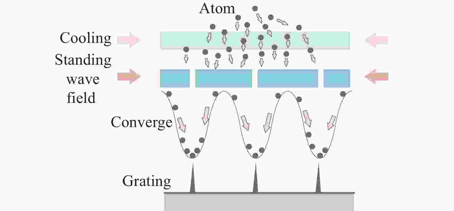
图 1 自溯源光栅制备原理图
Figure 1. Schematic diagram of self-traceable grating preparation
光栅衍射满足光栅方程:
$$ d\left(\sin \theta_i+\sin \theta_q\right)=m \lambda$$ (1) 式中:d、θi、θq、m、λ分别为光栅周期、入射角、衍射角、衍射级次、入射波长。自溯源光栅衍射示意图如图2所示,h、φ、ψ分别为光栅槽深、入射面与XZ平面的夹角、入射面与电场方向的夹角。图中,光栅结构划分为入射/反射区、光栅区和透射区,入射/反射区和透射区的折射率分别为n1和n2,光栅区折射率是介质为ngr和nrd的周期性分布。
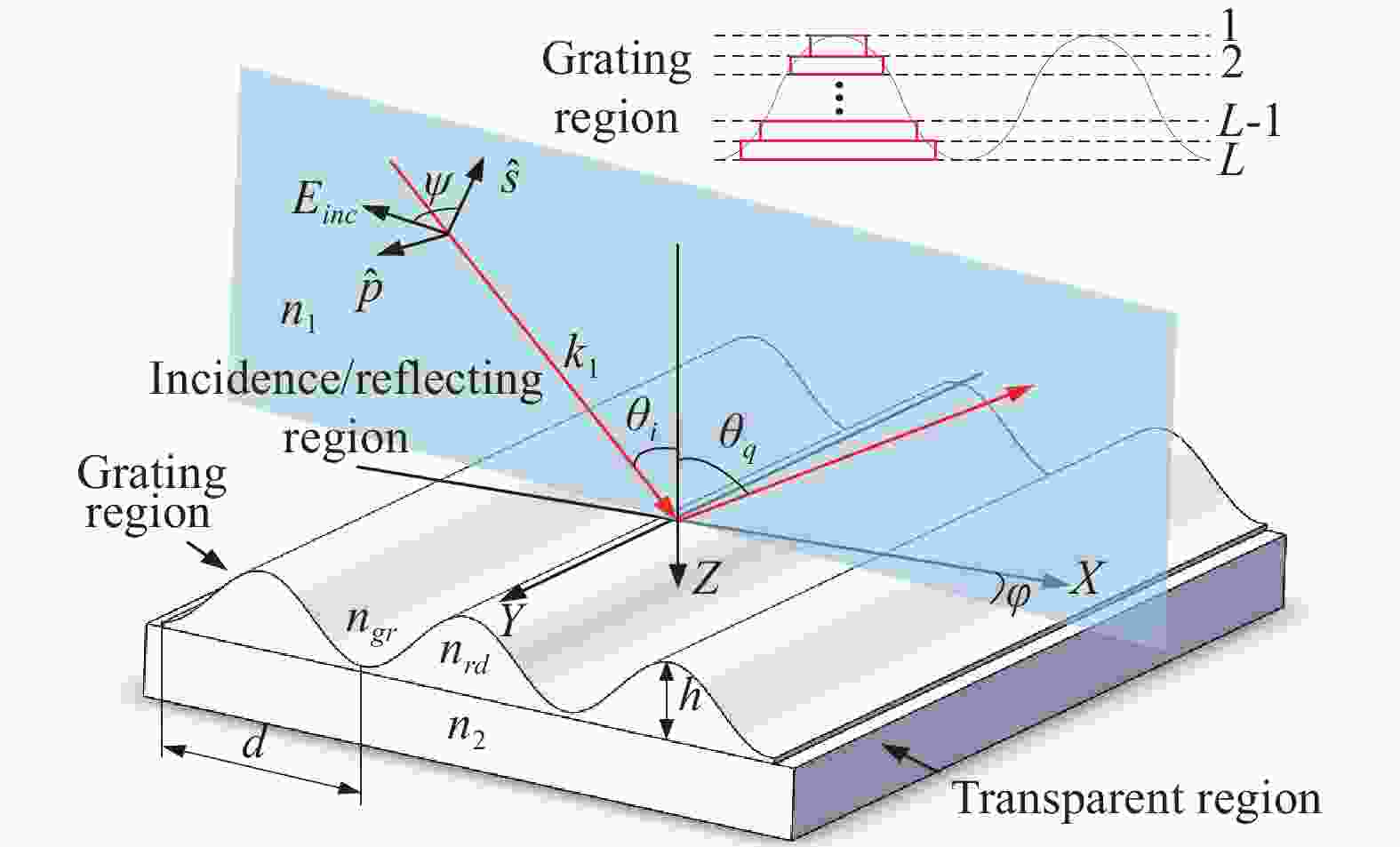
图 2 自溯源光栅衍射示意图
Figure 2. Schematic diagram of the self-traceable grating diffraction
由光栅制备方法可知,自溯源光栅结构为类正弦型,文中采用梯形光栅处理方法,将类正弦型的光栅结构进行矩形分层,图2将光栅分为L层,进而建立基于严格耦合波理论的光栅衍射模型[9, 15-16]。文中入射光束以TM偏振态入射光栅表面,电场矢量仅在X方向和Z方向存在分量,磁场矢量仅在Y方向存在分量,其他方向电磁场分量均为零。
入射/反射区域(z < 0)和透射区域(z > h)的归一化磁场为:
$$ {H_{1,y}} = {H_{inc}} + \sum\limits_i {{R_i}} \exp [ - j({k_{xi}}x + {k_{1,zi}}z)] $$ (2) $$ {H_{2,y}} = \sum\limits_i {{T_i}} \exp \{ - j[{k_{xi}}x + {k_{2,zi}}(z - h)]\} $$ (3) 式中:Hinc为归一化磁场;i为衍射级次;Ri和Ti分别表示第i级反射级次和透射级次的归一化电场振幅;kxi为x方向的波矢分量。
光栅区(0< z <h)的电磁场分量为:
$$ {E_{gx}} = - j\sqrt {\frac{{{\varepsilon _0}}}{{{\mu _0}}}} \sum\limits_i {{S_{xi}}(z)\exp ( - j{k_{xi}}x)} $$ (4) $$ {H_{gy}} = \sum\limits_i {{U_{yi}}} (z)\exp ( - j{k_{xi}}x) $$ (5) 式中:ε0为真空介电常数;μ0为真空磁导率;Sxi(z)为X方向电场分量的第i级级次振幅;Uyi(z)为Y方向磁场分量的第i级级次振幅。
上式代入麦克斯韦方程组并简化可得:
$$ {\partial ^2}{U_y}(z)/\partial {z^2} = EA{U_y}(z) $$ (6) 式中:A=KxE−1Kx−k02,E为由εh组成的介电常数矩阵,Kx为由kxi组成的对角矩阵,上述矩阵均为n维方阵,n为Fourier展开级次。
文中对自溯源光栅区域(0< z <h)进行矩形分层,其第l层切向电磁场分量的归一化振幅可以用该层特征向量和特征值表示为:
$$ \begin{split} {S_{l,x}} =& \sum\limits_m {{w_{l,m}}} \{ C_{l,m}^ + \exp [{q_{l,m}}(z - {H_l})] + \\ & C_{l,m}^ - \exp [ - {q_{l,m}}(z - {H_l} + {h_l})]\} \end{split} $$ (7) $$\begin{split} {U_{l,y}} =& \sum\limits_m {{w_{l,m}}} \{ {q_{l,m}}C_{l,m}^ + \exp [{q_{l,m}}(z - {H_l})] - {q_{l,m}}C_{l,m}^ - \cdot\\ & \exp [ - {q_{l,m}}(z - {H_l} + {h_l})]\} /{k_0} \end{split} $$ (8) 式中:Sl,xi和Ul,yi分别为光栅第l层的电磁场分量;hl为光栅第l层的厚度;ql,m为第l层矩阵ElAl的特征值;wl,m为对应的特征向量;Hl为到第l层光栅的深度。
在光栅第一层与入射/反射区域边界处,即Z=0,边界条件满足:
$$ \begin{split} & {\delta _{i0}} + R = {W_1}{X_1}C_1^ + + {W_1}C_1^ - \\ & j{k_1}{\delta _{i0}}\cos \theta + j{K_{1,zi}}R = - {W_1}{Q_1}{X_1}C_1^ + + {W_1}{Q_1}C_1^ - \\ \end{split} $$ (9) 在光栅第l−1层与第l层边界处,Z=Hl−1,边界条件满足:
$$ \begin{split} & {W_{l - 1}}C_{l - 1}^ + + {W_{l - 1}}{X_{l - 1}}C_{l - 1}^ - = {W_l}{X_l}C_l^ + + {W_l}C_l^ - \\ & {W_{l - 1}}{Q_{l - 1}}C_{l - 1}^ + - {W_{l - 1}}{Q_{l - 1}}{X_{l - 1}}C_{l - 1}^ - = - {W_l}{Q_l}{X_l}C_1^ + + {W_l}{Q_l}C_l^ - \\ \end{split} $$ (10) 在光栅最后一层与透射区域边界处,Z=Hl,边界条件满足:
$$ \begin{gathered} {W_L}C_L^ + + {W_L}{X_L}C_L^ - = T \\ {W_L}{Q_L}C_L^ + - {W_L}{Q_L}{X_L}C_L^ - = j{K_{2,zi}}T \\ \end{gathered} $$ (11) 求得TM偏振态下各级次反射效率和透射效率:
$$ D{E_{ri}} = {R_i}R_i^*{Re} \left(\frac{{{k_{1,zi}}}}{{{k_1}\cos \theta }}\right) $$ (12) $$ D{E_{ti}} = {T_i}T_i^*{Re} \left(\frac{{{k_{2,zi}}n_1^2}}{{{k_1}n_2^2\cos \theta }}\right) $$ (13) 式中:DEri为第i级反射级次的衍射效率;DEti为第i级透射级次的衍射效率。
-
衍射强度大小,则取决于光栅的反射率[17]以及其他多种因素,由于自溯源光栅的尺寸为1.5 mm×3.0 mm,因此其反射率对衍射强度的影响最大。文中光束入射自溯源型光栅,无+1级次衍射光,故仅分析光栅−1级次衍射效率。Gsolver是由美国Grating Solver Development公司开发解决光栅衍射效率求解问题的建模软件,能够准确求解不同光栅结构参数、不同入射条件下各级次衍射效率。根据上述模型,计算不同光栅结构、不同入射条件下自溯源光栅的衍射效率,利用Gsolver仿真验证严格耦合波理论自编程的理论可行性。文中在分析某一结构参数对衍射效率的影响时,将该参数设为变量、其他参数设为常量进行分析[18]。光栅初始仿真参数为:周期d = 212.8 nm、槽深h = 15 nm、折射率n1=ng =1,根据光学建模软件Gslover可知,n2=5.42141− i 0.250 56、 nrd = 2.050 09−i 2.897 05。入射条件为:入射波长λ = 405 nm、入射角θ = 70°、入射光束为TM偏振态。
-
入射平面与电场方向夹角 ψ = 0°时,为TM偏振态入射;ψ = 90°时,为TE偏振态入射。图3为入射平面与电场方向夹角从0°~ 90°时光栅−1级衍射效率,TM偏振态入射时,自溯源光栅的−1级衍射效率为3.8%,随着入射平面与电场方向夹角增大,光栅衍射效率逐渐减小,TE偏振态时,衍射效率减小至零,因此在自溯源光栅的实际应用中,光束以TM偏振态入射时,可以使光栅衍射利用率最高。可以看出图中蓝线即根据上文建立的衍射效率模型计算得到的结果和红线即Gsolver仿真软件的仿真结果十分吻合,且两者绝对偏差仅在±0.0012范围内。

图 3 (a)不同偏振态下自溯源光栅−1级衍射效率;(b)衍射效率偏差曲线
Figure 3. (a) Diffraction efficiency of self-traceable grating −1th-order under different polarization states; (b) Diffraction efficiency deviation curve
由光栅方程和已知参数可计算出自溯源光栅的−1级次衍射光出现时对应的临界入射角为64.6°。如图4所示,入射角从60°~64.6°时,自溯源光栅无−1级次衍射现象;64.6°~67°变化时,衍射效率迅速变大至3.75%;67°~80°变化时,衍射效率处于平稳峰值状态;80°~90°变化时,衍射效率减小至零。因此,当固定其他参数,光束入射角控制在67°~80°范围内,能保证自溯源光栅衍射效率值最大。耦合波理论计算的衍射效率值与仿真值的绝对偏差在±0.0015范围内。

图 4 (a) 不同入射角下的衍射效率; (b) 衍射效率偏差曲线
Figure 4. (a) Diffraction efficiency at different incidence angles; (b) Diffraction efficiency deviation curve
同一频率的波在不同介质中的传播速度不同,故波长也不同;不同入射波长入射自溯源光栅的光栅区和透射区时,其介电常数会发生改变,从而影响衍射效率值。图5为入射波长由100 nm变化到450 nm,对应的自溯源光栅的−1级次衍射效率。入射波长在400 nm左右时,自溯源光栅的−1级次峰值衍射效率为4%。耦合波分析的计算值与仿真值之间的绝对偏差在±0.0015范围内,结果非常吻合。
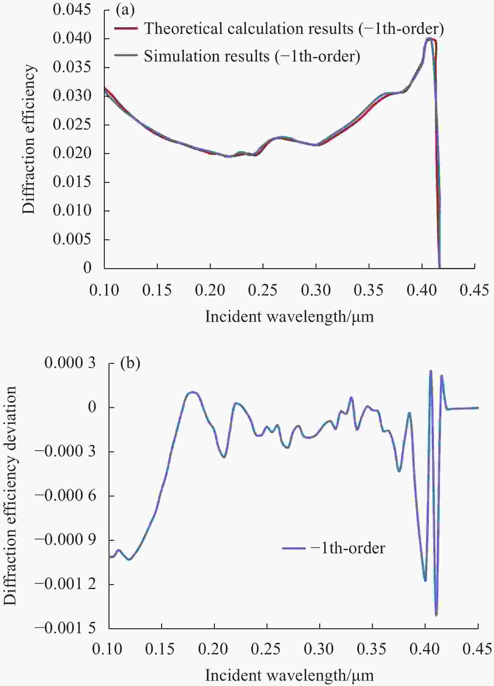
图 5 (a) 不同入射波长下的衍射效率;(b) 衍射效率偏差曲线
Figure 5. (a) Diffraction efficiency at different incident wavelengths; (b) Diffraction efficiency deviation curve
激光入射角波长和入射角共同影响光栅的衍射效率。图6为不同入射角随入射波长变化的光栅−1级衍射效率曲线,入射波长为420 nm左右,入射角为80°时自溯源光栅的衍射效率达到最高约为4.3%。对于自溯源光栅的Littrow结构,入射波长在400~415 nm范围内,其入射角在70°~77°范围内,衍射效率为4%左右,接近最大值。不同入射波长下,入射角度对其衍射效率的影响只在一个很小的范围内;不同入射角度下,入射波长对衍射效率的影响显著,4%衍射效率值对应的入射波长集中在390~410 nm范围内,因此,为了获得较高的衍射效率,自溯源入射角度和入射波长必须控制在合理的范围内。
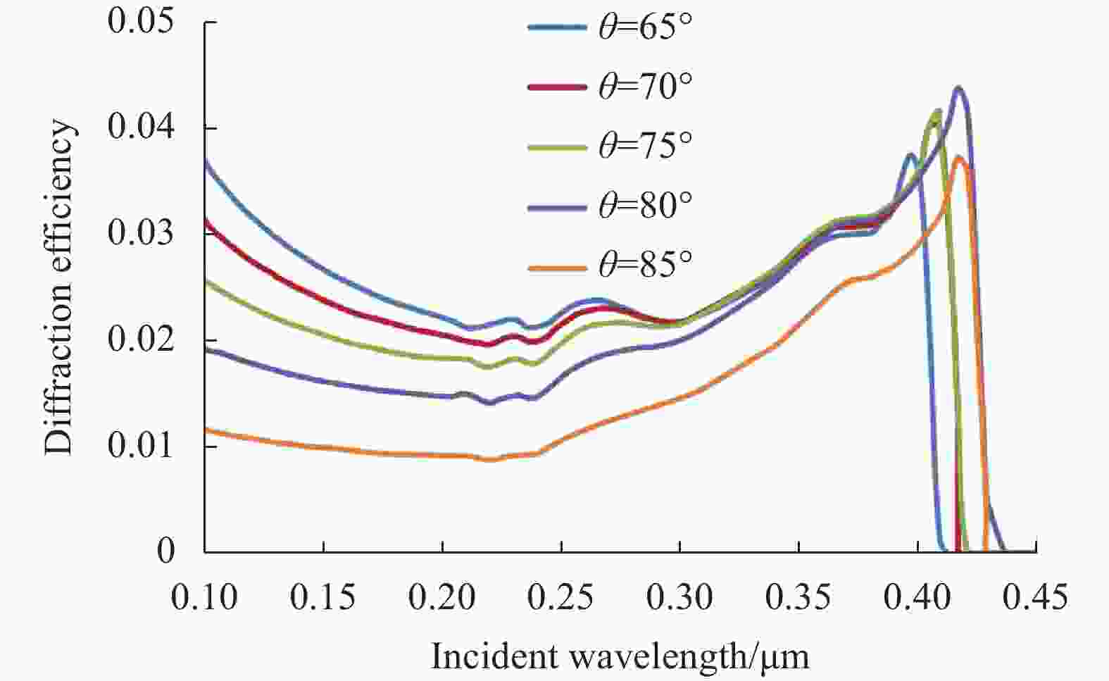
图 6 不同入射角随入射波长变化的衍射效率
Figure 6. Diffraction efficiencies of different incidence angles varying with the incident wavelength
-
自溯源光栅的制备过程决定光栅最终的结构,其结构参数直接影响衍射效率值,从而限制自溯源光栅的应用。如图7所示,光栅刻槽深度增加时,其−1级次衍射效率值呈线性增大,因此在光栅制备的过程中需结合其他参数,在条件允许下考虑增大光栅的刻槽深度。对于自溯源光栅,由于其制备原理,光栅的周期被固定在212.8 nm处,若通过仿真改变光栅周期,其衍射效率变化曲线如图8所示,212.8 nm处对应的衍射效率达到最大为4%,周期值增加时,衍射效率逐渐减小;根据光栅方程,入射波长为405 nm时,对于周期小于196 nm的光栅,其−1级衍射效率为零。模型计算与仿真之间的绝对偏差在±0.0015范围内。
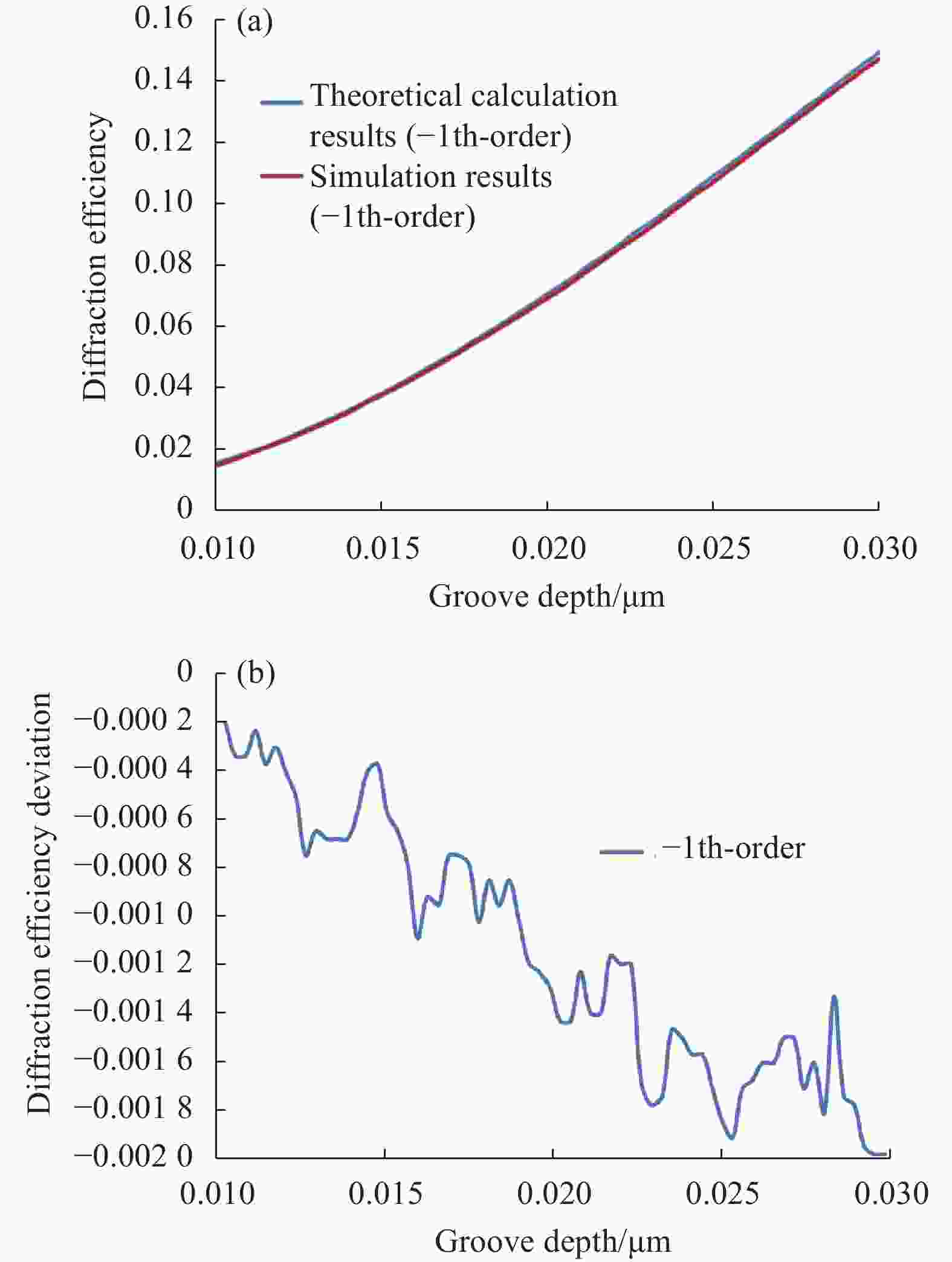
图 7 (a) 不同光栅槽深下的衍射效率;(b) 衍射效率偏差曲线
Figure 7. (a) Diffraction efficiency at different grating groove depths; (b) Diffraction efficiency deviation curve

图 8 (a)不同光栅周期下衍射效率;(b)衍射效率偏差曲线
Figure 8. (a) Diffraction efficiency at different grating periods; (b) Diffraction efficiency deviation curve
图9给出了光束以不同角度入射到不同周期的自溯源光栅时,光栅的衍射效率变化趋势。由此可以看出,70°、75°和80°的入射角度对应的随光栅周期变化的光栅衍射效率曲线几乎重合,其峰值效率对应的光栅周期在212.8 nm附近。而入射角为65°和85°对应的峰值效率明显降低,且入射角为85°的峰值效率对应的光栅周期偏离212.8 nm。

图 9 不同入射角随光栅周期变化的衍射效率
Figure 9. Diffraction efficiencies of different incidence angles varying with the grating period
-
在Littrow结构中,读数头与光栅之间的距离对位移测量无影响,因此光栅和读数头的安装允差大;对于相同波长的激光,Littrow入射可以使用更高刻线密度的光栅,有利于提高系统的光学分辨力;可以提高激光能量的利用率[19]。由光栅方程知,当激光入射波长改变,光栅的Littrow角随之变化。表1为不同Littrow角入射时,自溯源光栅的−1级次衍射效率,Littrow角为77.5°时,光栅衍射效率处于峰值,且接近非Littrow结构中自溯源光栅的衍射效率峰值;Littrow角由60°变化到87.5°,光栅衍射效率增大至4.2%后减小。由于采用Littrow结构时,自溯源光栅的衍射效率与非Littrow结构中光栅的衍射效率无异,故在实际应用中可考虑使用Littrow结构光路。
表 1 不同Littrow角的光栅−1级次衍射效率
Table 1. Grating −1th-order diffraction efficiency at different Littrow angles
Littrow
angle
θ/(°)Grating
diffraction
efficiencyIncident
wavelength λ/
nmLittrow
angle
θ/(°)Grating
diffraction
efficiencyIncident
wavelength
λ/nm60.0 2.953% 368.58 75.0 4.043% 411.10 62.5 2.997% 377.51 77.5 4.202% 415.51 65.0 3.122% 385.72 80.0 4.201% 419.13 67.5 3.329% 393.20 82.5 3.889% 421.96 70.0 3.570% 399.93 85.0 3.430% 423.98 72.5 3.816% 405.90 87.5 1.772% 425.20 -
根据上述仿真分析,搭建实验平台,如图10所示,验证入射角对自溯源光栅衍射效率的影响。实验系统主要包括:由同济大学研制的周期为212.8 nm的自溯源光栅、功率为105 mW,出射波长为405 nm激光器、激光准直器、偏振分光棱镜、2 mm小孔光阑、旋转台、光电探测器和示波器。实验中激光器发出405 nm的光束,出射光经过准直扩束器和2 mm小孔光阑入射到偏振分光棱镜,获取TM偏振光后入射到自溯源光栅表面。控制旋转台改变光束入射角度,入射角范围为65°~85°,一次改变2°。利用光电探测器探测光束入射光栅前的光强Ii以及入射光栅后的−1级衍射光的光强Iq,通过Iq / Ii×100%得到自溯源光栅−1级衍射效率。六次实验结果见表2。

图 10 系统实物图
Figure 10. System physical diagram
表 2 不同入射角下,自溯源光栅−1级衍射效率实际测量结果
Table 2. Actual measurement of diffraction efficiency of self-traceable grating −1th-order at different incidence angles
Incident
angle θ/(°)Self-traceable grating diffraction efficiency measurement Maximum absolute deviation 1 2 3 4 5 6 65 0.31% 0.37% 0.35% 0.37% 0.40% 0.33% 2.59% 67 0.54% 0.52% 0.62% 0.52% 0.56% 0.52% 3.21% 69 0.63% 0.58% 0.67% 0.51% 0.57% 0.58% 3.23% 71 0.63% 0.52% 0.63% 0.47% 0.52% 0.52% 3.33% 73 0.54% 0.50% 0.57% 0.42% 0.52% 0.51% 3.38% 75 0.50% 0.44% 0.42% 0.37% 0.47% 0.47% 3.42% 77 0.42% 0.37% 0.32% 0.31% 0.37% 0.42% 3.47% 79 0.36% 0.27% 0.26% 0.21% 0.30% 0.31% 3.53% 81 0.26% 0.21% 0.19% 0.16% 0.21% 0.21% 3.48% 83 0.21% 0.15% 0.16% 0.14% 0.15% 0.16% 3.30% 85 0.11% 0.10% 0.11% 0.10% 0.09% 0.11% 2.96% 表2中,绝对偏差为角度对应的实际测量结果与图4中角度对应的理论结果之间的差值,可以看出实际测得的自溯源光栅衍射效率值的变化趋势与理论计算的变化趋势一致,但低于理论计算值,这是由于自溯源光栅制备工艺限制了其制备尺寸,相比于普通光栅,自溯源光栅的尺寸仅有 1.5 mm×3.0 mm,导致激光光束不能完全入射到自溯源光栅表面;激光光束斜入射自溯源光栅时会产生遮挡效应[20];自溯源光栅刻槽的粗糙度会造成部分衍射光变为杂乱的漫反射,影响衍射效率;自溯源光栅处于大气环境中,而空气中含有灰尘等杂质颗粒,从而会影响粗糙度,降低衍射效率[21]。
-
文中通过建立自溯源光栅的严格耦合波模型、求解激光入射自溯源光栅结构后各区域满足电磁场边界条件麦克斯韦方程组的精确解,实现了对自溯源光栅衍射效率的分析。通过对自溯源光栅衍射效率的测量与研究,为自溯源光栅的制备与应用提供重要依据。在自溯源光栅的实际应用中,需要结合各参数对衍射效率的影响,选择最佳入射条件以实现衍射效率最大化。对于自溯源光栅的衍射效率分析,后续将从自溯源光栅制备原理入手,研究制备过程中影响自溯源光栅结构参数的因素,结合文中的光栅衍射效率分析,从而制备出最大化衍射效率的自溯源光栅。
Analysis and study of the diffraction efficiency of self-traceable grating
-
摘要: 基于矢量衍射理论并采用严格耦合波方法建立了一种新型的自溯源光栅正弦结构及入射条件与衍射效率的理论模型;通过控制变量法分析了自溯源光栅结构参数、激光入射条件对衍射效率的影响规律;搭建了光栅衍射效率测量系统;结合光栅方程,计算了不同Littrow角对应的衍射效率。仿真结果表明:入射波为TM偏振态、入射波长为420 nm、入射角为80°时,自溯源光栅−1级衍射效率处于峰值状态,为4.3%;在Littrow结构中,入射波为TM偏振态、入射波长为415.51 nm、Littrow角为77.5°时,自溯源光栅−1级衍射效率达到最大,且接近非Littrow角对应的自溯源光栅的峰值衍射效率。实验结果表明:入射波为TM偏振态、入射波长为405 nm、入射角从65°~85°改变时,自溯源光栅的衍射效率呈上升到平稳再下降的趋势,67°~80°改变时,其衍射效率达到平稳最大值,其结果为0.6%左右,其衍射效率变化趋势与理论计算结果一致。Abstract:
Objective Diffraction gratings are widely used in ultra-high precision displacement measurement systems, instrument calibration and other fields. The self-traceable grating prepared by atomic lithography is different from ordinary diffraction gratings in that its characteristic parameters can be directly traced to "meters" through natural constants, so the grating has the natural advantage of being used as a ruler without measuring a fixed value. Diffraction efficiency is an important indicator to measure the performance of gratings, and the diffraction efficiency of self-traceable gratings will affect the accuracy and precision of measurement results. Therefore, by analyzing the diffraction efficiency of self-traceable gratings, an important basis is provided for the preparation and application of self-traceable gratings. Methods Based on the vector diffraction theory and rigorous coupled-wave method, a theoretical model of self-traceable grating with a sinusoidal structure and its diffraction efficiency under different incident conditions are established (Fig.2). The influence of structural parameters and laser incident conditions on the diffraction efficiency of self-traceable gratings are analyzed using the method of controlling variables. The results of model calculation are compared with the Gsolver simulation results to verify the feasibility of model calculation. A measurement system for grating diffraction efficiency is constructed (Fig.10). Combined with the grating equation, the diffraction efficiency corresponding to different Littrow angles is calculated (Tab.1). Results and Discussions The simulation results show that the diffraction efficiency of the self-traceable grating −1-order is at its peak state, reaching 4.3%, when the incident wave is TM polarized, the incident wavelength is 420 nm, and the incident angle is 80° (Fig.6). In the Littrow structure, the diffraction efficiency of the self-traceable grating −1-order is at its maximum, and is close to the peak diffraction efficiency of the self-traceable grating corresponding to non-Littrow angles, when the incident wave is TM polarized, the incident wavelength is 415.51 nm, and the Littrow angle is 77.5° (Tab.1). The experimental results show that the variation trend of diffraction efficiency is consistent with the theoretical calculation results (Tab.2, Fig.4). Conclusions The diffraction efficiency of the self-traceable grating is analyzed by establishing a strict coupled wave model of the self-traceable grating and solving the accurate solution of Maxwell's equation system that satisfies the boundary conditions of the electromagnetic field in each region after the laser incident self-traceable grating structure. Through the measurement and research of the diffraction efficiency of self-traceable gratings, this paper provides an important basis for the preparation and application of self-traceable gratings. In the practical application of self-tracing gratings, it is necessary to combine the influence of various parameters on the diffraction efficiency and select the best incident conditions to maximize the diffraction efficiency. For the diffraction efficiency analysis of self-traceable gratings, the factors affecting the structural parameters of self-traceable gratings during the preparation process will be studied from the preparation principle of self-traceable gratings, and combined with the grating diffraction efficiency analysis in this paper, so as to prepare a self-traceable grating that maximizes diffraction efficiency. -
图 3 (a)不同偏振态下自溯源光栅−1级衍射效率;(b)衍射效率偏差曲线
Figure 3. (a) Diffraction efficiency of self-traceable grating −1th-order under different polarization states; (b) Diffraction efficiency deviation curve
图 4 (a) 不同入射角下的衍射效率; (b) 衍射效率偏差曲线
Figure 4. (a) Diffraction efficiency at different incidence angles; (b) Diffraction efficiency deviation curve
图 5 (a) 不同入射波长下的衍射效率;(b) 衍射效率偏差曲线
Figure 5. (a) Diffraction efficiency at different incident wavelengths; (b) Diffraction efficiency deviation curve
图 6 不同入射角随入射波长变化的衍射效率
Figure 6. Diffraction efficiencies of different incidence angles varying with the incident wavelength
图 7 (a) 不同光栅槽深下的衍射效率;(b) 衍射效率偏差曲线
Figure 7. (a) Diffraction efficiency at different grating groove depths; (b) Diffraction efficiency deviation curve
图 8 (a)不同光栅周期下衍射效率;(b)衍射效率偏差曲线
Figure 8. (a) Diffraction efficiency at different grating periods; (b) Diffraction efficiency deviation curve
图 9 不同入射角随光栅周期变化的衍射效率
Figure 9. Diffraction efficiencies of different incidence angles varying with the grating period
表 1 不同Littrow角的光栅−1级次衍射效率
Table 1. Grating −1th-order diffraction efficiency at different Littrow angles
Littrow
angle
θ/(°)Grating
diffraction
efficiencyIncident
wavelength λ/
nmLittrow
angle
θ/(°)Grating
diffraction
efficiencyIncident
wavelength
λ/nm60.0 2.953% 368.58 75.0 4.043% 411.10 62.5 2.997% 377.51 77.5 4.202% 415.51 65.0 3.122% 385.72 80.0 4.201% 419.13 67.5 3.329% 393.20 82.5 3.889% 421.96 70.0 3.570% 399.93 85.0 3.430% 423.98 72.5 3.816% 405.90 87.5 1.772% 425.20  下载: 导出CSV
表 2 不同入射角下,自溯源光栅−1级衍射效率实际测量结果
Table 2. Actual measurement of diffraction efficiency of self-traceable grating −1th-order at different incidence angles
Incident
angle θ/(°)Self-traceable grating diffraction efficiency measurement Maximum absolute deviation 1 2 3 4 5 6 65 0.31% 0.37% 0.35% 0.37% 0.40% 0.33% 2.59% 67 0.54% 0.52% 0.62% 0.52% 0.56% 0.52% 3.21% 69 0.63% 0.58% 0.67% 0.51% 0.57% 0.58% 3.23% 71 0.63% 0.52% 0.63% 0.47% 0.52% 0.52% 3.33% 73 0.54% 0.50% 0.57% 0.42% 0.52% 0.51% 3.38% 75 0.50% 0.44% 0.42% 0.37% 0.47% 0.47% 3.42% 77 0.42% 0.37% 0.32% 0.31% 0.37% 0.42% 3.47% 79 0.36% 0.27% 0.26% 0.21% 0.30% 0.31% 3.53% 81 0.26% 0.21% 0.19% 0.16% 0.21% 0.21% 3.48% 83 0.21% 0.15% 0.16% 0.14% 0.15% 0.16% 3.30% 85 0.11% 0.10% 0.11% 0.10% 0.09% 0.11% 2.96%
下载: 导出CSV
-
[1] Hu Pengcheng, Chang Di, Tan Jiubin, et al. Displacement measuring grating interferometer: A review [J]. Frontiers of Information Technology & Electronic Engineering, 2019, 20(5): 631-654. [2] Perry M D, Britten J A, Boyd R D, et al. High-efficiency multilayer dielectric diffraction gratings [J]. Optics Letters, 1995, 20(8): 940-942. doi: 10.1364/OL.20.000940 [3] Deng X, Li T B, Cheng X B. Self-traceable grating reference material and application [J]. Optics and Precision Engineering, 2022, 30(21): 2608-2625. doi: 10.37188/OPE.20223021.2608 [4] Lei L, Li Y, Deng X, et al. Laser-focused Cr atomic deposition pitch standard as a reference standard [J]. Sensors & Actuators: A Physical, 2015, 222(1): 184-193. [5] Lin Z, Yao Y, Xie Z, et al. Chromium Self-traceable length standard: investigating geometry and diffraction for length traceability chain[EB/OL]. https://arxiv.org/abs/2306.14083(2023-06-25) [6] Rosen G. Particlelike solutions to nonlinear scalar wave theories [J]. Journal of Mathematical Physics, 1965, 6(8): 1269-1272. doi: 10.1063/1.1704769 [7] Moharam M G, Grann E B, Pommet D A, et al. Formulation for stable and efficient implementation of the rigorous coupled-wave analysis of binary gratings [J]. JOSA A, 1995, 12(5): 1068-1076. doi: 10.1364/JOSAA.12.001068 [8] Yang Ken, Xie Xiangsheng, Zhou Jianying. Generalized vector wave theory for ultrahigh resolution confocal optical microscopy [J]. Journal of the Optical Society of America A, Optics, Image Science, and Vision, 2017, 34(1): 61-67. doi: 10.1364/JOSAA.34.000061 [9] Shang Ping. Study on the key technology of high-resolution diffraction grating interfero- metric transducer of linear displacements [D]. Hefei: Hefei University of Technology, 2012. (in Chinese) [10] Werner P. On an integral equation in electromagnetic diffraction theory [J]. Journal of Mathematical Analysis and Applications, 1966, 14(3): 455-462. [11] Petit R, Cadilhac M. On the roles of physical intuition, computation, and mathematical analysis in electromagnetic diffraction theory [J]. Radio Science, 1987, 22(7): 1068-1076. [12] Lyalinov M A. Boundary-contact problems of the electromagnetic theory of diffraction [J]. Radiophysics & Quantum Electronics, 1993, 36(6): 331-345. [13] Sugisaka J I, Yasui T, Hirayama K. Efficient analysis of diffraction grating with 10 000 random grooves by difference-field boundary element method [J]. IEICE Transactions on Electronics, 2017, 100(1): 27-36. doi: 10.1587/transele.E100.C.27 [14] Delâge A, Dossou K. Polarisation dependent loss calculation in echelle gratings using finite element method and Rayleigh expansion [J]. Optical and Quantum Electronics, 2004, 36(1-3): 223-238. doi: 10.1023/B:OQEL.0000015642.08203.e9 [15] Afshar B A, Soltanpour P, Sabatyan A. Comprehensive analysis of diffraction efficiency of conical beam from sub-wavelength binary metallic grating using rigorous coupled-wave theory [J]. Optik International Journal for Light and Electron Optics, 2015, 126(24): 5504-5508. doi: 10.1016/j.ijleo.2015.09.111 [16] Shang Ping. Study on the key technology of high-resolution diffraction grating interfero- metric transducer of linear displacements [D]. Hefei: Hefei University of Technology, 2017. (in Chinese) [17] Zheng Q Q, Wang C Y, Wang Z S, et al. Research on diffraction characteristic of liquid crystal polarization grating under oblique incidence [J]. Infrared and Laser Engineering, 2022, 51(7): 20210511. (in Chinese) [18] Yang G H, Wang Y, Li J, et al. Diffraction efficiency of enhanced phase grating [J]. Acta Optica Sinica, 2021, 41(12): 1205001. (in Chinese) [19] Wang L J, Zhang M, Zhu Y, et al. A displacement measurement system for ultra-precision hetero- dyne Littrow grating interferometer [J]. Optics and Precision Engineering, 2017, 25(12): 2975-2985. (in Chinese) doi: 10.3788/OPE.20172512.2975 [20] Yang L L. Measurement of diffraction efficiency for diffractive optical elements with oblique incidence [J]. Infrared and Laser Engineering, 2018, 47(1): 0117003. (in Chinese) doi: 10.3788/IRLA201847.0117003 [21] Luo J Y, Guo Z H, Huang H, et al. Synchrotron radiation research on diffraction efficiency of multilayer coated grating [J]. Acta Optica Sinica, 2021, 41(14): 1405001. (in Chinese) -

 点击查看大图

计量
- 文章访问数: 96
- HTML全文浏览量: 17
- PDF下载量: 21
- 被引次数: 0

