


-
视宁度是用于描述天文观测目标受到大气湍流影响的物理量[1],镜面视宁度是影响望远镜成像质量的重要因素之一。大型太阳望远镜的主镜持续受到太阳辐射的影响,导致镜面温度高于环境空气温度。在镜面温差的作用下镜面附近的空气被加热,引起空气密度分层不均匀[2],造成反常大气折射,产生镜面视宁度,使太阳望远镜像质退化。由于2 m以上级大口径太阳望远镜的玻璃封窗加工难度大,无法通过真空式镜筒的方法来消除镜面视宁度。当采用开放式镜筒时,大型太阳望远镜主镜附近会产生较强的镜面视宁度效应,对太阳望远镜高分辨率和高精度观测影响很大。
近年来,国外已开展了大型太阳望远镜镜面视宁度的研究工作。国外研究机构主要是针对不同情况加热镜面的视宁度研究,在此基础上,分析增加主动措施的影响以及总结出相关的经验公式。Lowne等[3]曾使用一个254 mm球面镜在不同海拔条件下研究自然通风和强制吹风的镜面视宁度情况。Lye等[4]使用一个620 mm平面镜分别测量增加外部气流前后的镜面视宁度数据。Lorenzo等[5]利用等比例缩小的40 mm平面镜,研究不同镜面温差时的镜面视宁度情况。国内较少有专家对太阳望远镜镜面视宁度进行实验研究[6],主要集中在望远镜温控系统、数值仿真、总结计算等方面的研究工作。Huang等[7] 针对1 m以下口径真空式镜筒太阳望远镜提出了“热管+液冷”的热光阑冷却方式,由于真空式镜筒不存在镜面视宁度,并未配备主镜主动温控系统;Zhang等[8]采用计算流体动力学方法进行仿真研究,模拟中国未来巨型望远镜的镜面视宁度结果;Liu等[9]总结了国外学者的实验经验公式结果,分段式计算及分析CLST主镜镜面视宁度效应。
太阳望远镜多采用格里高利光学系统,其主镜为非球面镜。国外的实验研究主要采用平面镜或球面镜进行实验,受限于镜面面形、有效口径、实验光路等因素,其实验结果的理论相关性较低。镜面视宁度是镜面和周围空气的耦合作用,国内只进行了数值模拟,尚未针对镜面视宁度的进行相关实验研究,直接实验探测是较为可靠的方案。为了控制主镜温度升高引起的附近镜面视宁度,需要定量地给出镜面温控目标。大口径太阳望远镜主镜多采用非球面镜,文中的实验平台使用1550 mm口径的双曲面镜进行研究,以提高实验结果的普适性。
针对以上情况,文中提出镜面视宁度效应的形成机制,建立主镜视宁度效应理论。基于大气湍流产生镜面视宁度的物理过程,搭建了1550 mm大口径双曲面镜的实验平台,通过自然对流和强迫对流实验,得到镜面和周围空气温差改变对镜面视宁度的影响,总结不同对流条件下的实验模型,并对太阳望远镜温控目标进行确定。结果表明:镜面与周围空气温度的温差与视宁度相关性很强,通过增加主动通风降低镜面视宁度。镜面温差是4 ℃条件下,自然对流时镜面视宁度为1.43″,镜面温差是3 ℃条件下,在0.2 m/s的强迫对流时镜面视宁度为 0.44″,在 1 m/s的强迫对流时镜面视宁度为 0.27″。通过该实验的研究,得到自然对流和强迫对流两种情况下的大气相干长度、弗劳德数和镜面视宁度等数据,其可以用于评价镜面视宁度和主镜温控系统的温控目标,为我国未来研制大型太阳望远镜在主镜温控方面奠定了基础。
-
望远镜的视宁度取决于大气湍流对光线折射率的湍流波动程度[10]。折射率N随星光抵达望远镜前所穿过大气层温度的变化而变化。根据Lorenz湿度扩展的Cauchy公式,在可见光波段的大气折射率可表示为[10]:
$$ N-1=77.6\times {10}^{-6}\times \left(1+\frac{7.52\times {10}^{-3}}{{\lambda }^{2}}\right) \left(P+4\;810\frac{\nu }{T}\right) $$ (1) 式中:λ为光线波长(单位:μm);P为大气压力(单位:hPa);T为大气温度(单位:K);υ为水蒸气压力(单位:mb)。
在极端条件下,湿度和压力才会产生显著的影响,但极端情况是与天文观测无关的大雾或海面等环境。因此,实验不讨论湿度和压力的作用,光线折射率与大气中的热湍流结构密切相关。
地面光学系统观测时,由大气湍流效应,观测图像出现模糊、闪烁、飘移等破环观测精度的现象[11-12]。Fried引入大气相干长度 $ {r}_{0} $来描述湍流的影响,也被称为Fried常数[13]。
-
文中讨论两种情况的镜面视宁度的物理过程,镜面上方气流不受外部空气运动影响或干扰的自然对流情况,以及自然对流模式下外部气流受干扰的湍流和强制对流的情况,如图1所示。

图 1 大气层流状态和湍流状态示意图
Figure 1. The laminar state and turbulent state diagram
-
近地面大气中,因太阳辐射强烈加热,望远镜内部镜面附近产生对流泡或羽流,表现为湍流状态的自然对流,其状态可由无量纲参数$ {F}_{r} $、$ {R}_{e} $、$ {P}_{r} $表示。弗劳德数$ {F}_{r} $可表征浮力做功,其由未明确定义的参考速度U定义则不方便使用。文中使用罗利数$ {R}_{a} $来分析,一般地,当$ {R}_{a} $< 4×10⁷时,流体运动为层流,尽管大气运动是不稳定的;当$ {R}_{a} $> 4×10⁷时,流体运动为湍流。
$$ {R}_{a}=\frac{{R_e}^{2}P_r}{F_r}=\frac{g\Delta {{ T}}{L}^{3}}{{{ T}}\nu k} $$ (2) 整体上看对流泡的流动是有规律的,实际上各个单体出现的时间和地点却是完全随机的。白天空气升温和夜间空气冷却,由于空气流动的不稳定性和夹卷作用,对流泡会部分地破碎为小尺度湍流。
根据Hertig[14]和Giovannoni[15]的实验结果,对于足够大的空间平面,在稳定的大气条件下,罗利数$ {R}_{a} $> 6×10⁵,湍流中心核长度$ {L}_{s} $> 3×10⁹ m时,为不稳定性对流单体。
$$ {L}_{s}=\frac{g{L}^{3}}{\nu k} $$ (3) 理论上,对流单体的高度取决于环境空气的稳定性。在稳定大气中,随机上下运动的对流泡反抗重力做功而失去动能,使湍流减弱,直到其能量耗尽。
-
强迫对流条件下,强迫气流和自然气流相互作用,壁面区的部分对流结构被破坏,仅有粘性导电区和湍流区两部分,使得平均温度梯度变小。湍流区的湍流扩散率随垂直高度的增大而迅速增大,导致温度波动减小。强迫对流的情况,粘性导电区和湍流区的交界面温度结构系数$ {C}_{T}^{2} $达到最大值随后趋于定值,且强迫对流时的变化速率大于自然对流。
使用无量纲参数弗劳德数$ {F}_{r} $、雷诺数$ {R}_{e} $量化分析强迫对流时的大气湍流状态,$ {F}_{r} $表示动能和势能的比值,$ {R}_{e} $是动能和摩擦耗散能量之比。强迫对流和自然对流相互作用产生混合湍流区,当弗劳德数$ {F}_{r} $较大时,强迫对流将占主导并将引导自然对流;当雷诺数$ {R}_{e} $较大时,自然对流仍是主导气流,将形成紊乱、不规则的紊流流场。在特征长度为L的水平表面上,$ {F}_{r} $、$ {R}_{e} $分别表示为:
$$ {F}_{r}=\frac{T{V}^{2}}{\Delta TgL} $$ (4) $$ {R}_{e}=\frac{{\rm{U}}L}{\upsilon } $$ (5) -
Zhang等指出,镜面视宁度影响图像的点扩散函数的半高全宽FWHM和大气湍流理论之间的关系可按如下公式计算[8]:
$$ \theta =0.98\frac{\lambda }{{r}_{0}} $$ (6) 式中:λ为波长,该实验中为632.8 nm;$ {r}_{0} $为Fried常数。
Sarazin指出,长时间曝光的波前误差均方根(RMS)$ {\sigma }_{\omega } $和大气相干长度$ {r}_{0} $的关系表示为[16]:
$$ {\sigma }_{\omega }^{2}=0.35\cdot {\lambda }^{2}\cdot {D}^{-{1}/{3}}{\cdot r}_{0}^{-{5}/{3}} $$ (7) 式中:λ为波长;D为光束孔径为1550 mm。
大气相干长度表示为:
$$ {r}_{0}={\left(0.35{\cdot \lambda }^{2}\cdot {D}^{-{1}/{3}}\cdot {\sigma }_{\omega }^{-2}\right)}^{{3}/{5}} $$ (8) 除此以外,文中还使用斯特尔比(Strehl Intensity)进行定量评估以测量镜面视宁度影响下的图像质量。为了提高以RMS波前误差计算斯特尔比近似值的精度,使用Mahajan简单经验表达式计算数据方法,表示式为[17]:
$$ S={{\rm{e}}}^{{-\left(2\pi {\mathrm{\sigma }}_{\omega }\right)}^{2}} $$ (9) 式中:$ {\sigma }_{\omega } $为波前误差的均方根。
利用公式(6)~(9),建立了大气相干长度$ {r}_{0} $和图像FWHM与波前误差均方根$ {\sigma }_{\omega } $之间的关系,如图2所示。

图 2 FWHM与Strehl Intensity之间的关系
Figure 2. Relationship between FWHM and Strehl Intensity
-
为了进行镜面视宁度实验,使用补偿器自准直检测方法,搭建了如图3所示的实验光路。实验光路由动态激光干涉仪、补偿镜组、大口径待测离轴主镜、平面反射镜组成,设备参数如表1所示。该实验使用4D 6000系列动态激光干涉仪作为测试仪器。激光干涉仪工作波段为632.8 nm,干涉仪镜头焦距为14 mm,补偿镜组口径为82 mm。大口径待测离轴主镜为双曲面镜,口径为1550 mm,离轴量为1500 mm,圆锥系数为 −1.063,表面镀铝膜。平面反射镜口径为1800 mm。
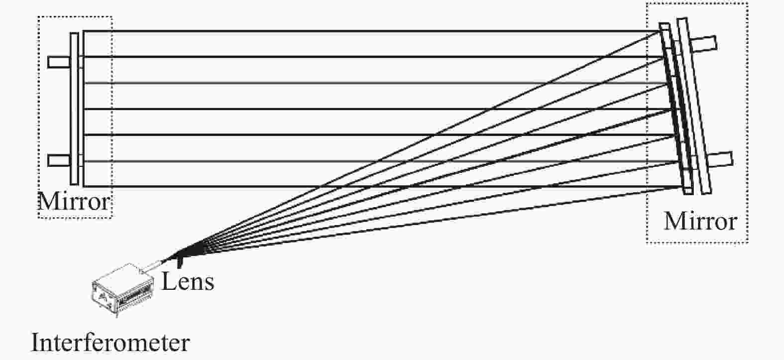
图 3 镜面视宁度实验光学原理图
Figure 3. Optical schematic of the mirror seeing experiment
激光干涉仪置于补偿器的焦点,其发出的光透射补偿镜组到待测离轴主镜上,经过大口径离轴主镜反射后成平行光束,经过平面反射镜自准直反射,再次经过待测离轴主镜与补偿镜组后进入干涉仪,形成干涉条纹。使用4D干涉仪进行系统波前检测,并记录测试系统的波前.dat数据。
表 1 设备参数表
Table 1. Equipment parameter list
Species Parameter 4D interferometer Diameter: 9 mm; Focal length: 14 mm
Working band: 632.8 nmCompensating mirror set Diameter: 82 mm; Material: H-K9L
Flat 1 curvature radius: −154.88 mm
Flat 2 curvature radius: −325.9 mm
Distance between mirrors: −27.506 mmLarge hyperboloid reflector primary mirror Diameter: 1550 mm; Off-axis distance: 1500 mm
Material: glass-ceramic; Coating:enhanced aluminumFlat mirror Diameter: 1800 mm; RMS: λ/40 (632.8 nm)
Material: glass-ceramic -
2022年9月15日至9月30日期间,笔者在23 ℃的光学实验室内进行实验,其实验照片如图4所示。

图 4 镜面视宁度实验照片
Figure 4. Photo of the mirror seeing experiment
系统总体布局如图5所示。实验开始前,主镜和平面镜背面安装了多个贴片式温度传感器,主镜和平面镜之间均匀搭建了空气温度传感器和超声波风速风向传感器,主镜两侧设有两台风向风速传感器,并匹配记录相关原始数据。大口径待测离轴主镜后方贴有外置数显的两块硅橡胶加热板,主动加热镜面,使主镜与环境空气温度存在0~4 K的温差变化。为了测量强迫通风对镜面视宁度的影响,在平行于主镜前表面的单侧方向使用电风扇吹风。实验中,所用主镜和平面镜选用微晶玻璃材料,其低热膨胀性可降低自身热变形的影响。电风扇未遮挡实验测试光路,其电动机产生的热量不会对实验结果产生影响。

图 5 系统总体布局(图中空心圆圈是贴片式温度传感器和空气温度传感器;空心圆柱是超声波风向风速传感器;红色长方形是硅橡胶加热板;梯形是电风扇)
Figure 5. System overall layout (The hollow circles are SMD temperature sensors and air temperature sensors; the hollow cylinder is the ultrasonic wind direction and speed sensor; the red rectangle is the silicone rubber heating plate; the trapezoid is the electric fan)
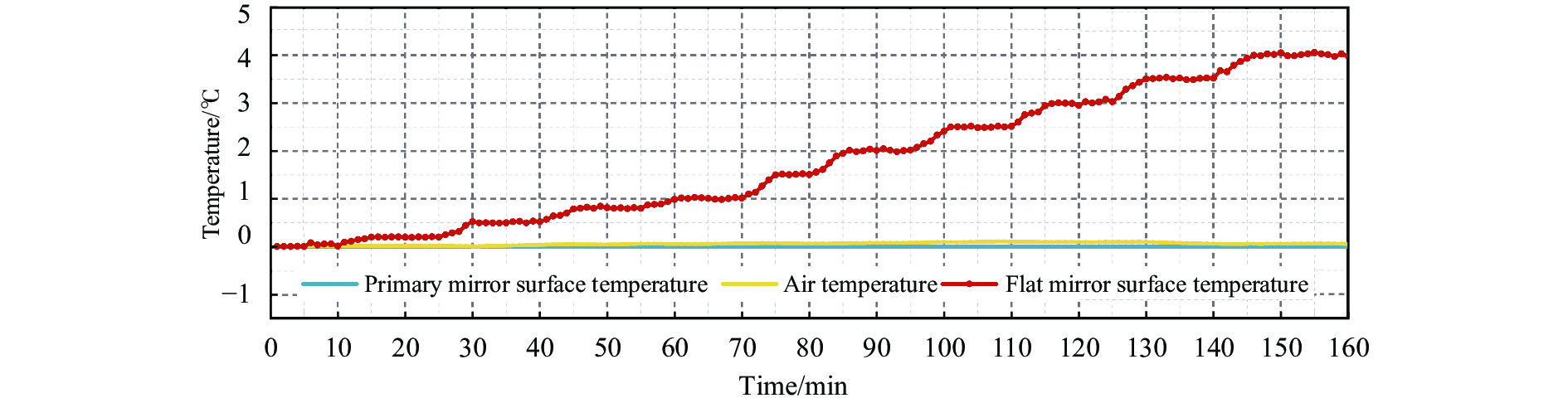
镜面温度传感器结果表示,主镜镜面温度升高,平面镜未出现明显的温度变化。环境空气温度和风速风向传感器结果表示,实验环境温度变化小于0.5 K,且不存在明显的风向风速切变,大气流动较稳定,因此大气自身的风切变产生的湍流和温度变化产生的湍流不会影响实验结果。通过统计,实验系统中强迫对流时布设的传感器数据与时间变化的关系曲线如图6所示,主镜镜面温度上升与环境温度温差越大,主镜镜面视宁度越大,平面镜与环境空气间不存在较大温差,因此可忽略平面镜的镜面视宁度效应。

图 6 自然对流时温度传感器随时间变化的曲线
Figure 6. Temperature sensors curve with time for free convection
-
实验结果揭示了镜面附近的空气湍流对大口径望远镜像质退化影响规律,分析自然对流和强迫对流条件下产生镜面视宁度的大气物理过程,并推导和验证经验公式。
-
实验中,通过4D干涉仪测量得到波前误差均方根$ {\sigma }_{\omega } $数据,使用MetroPro软件进行计算。每次实验过程在半小时以上并进行连续测量,单次测量时间均保持30 s以上,保证实验数据较为准确,如图7所示。
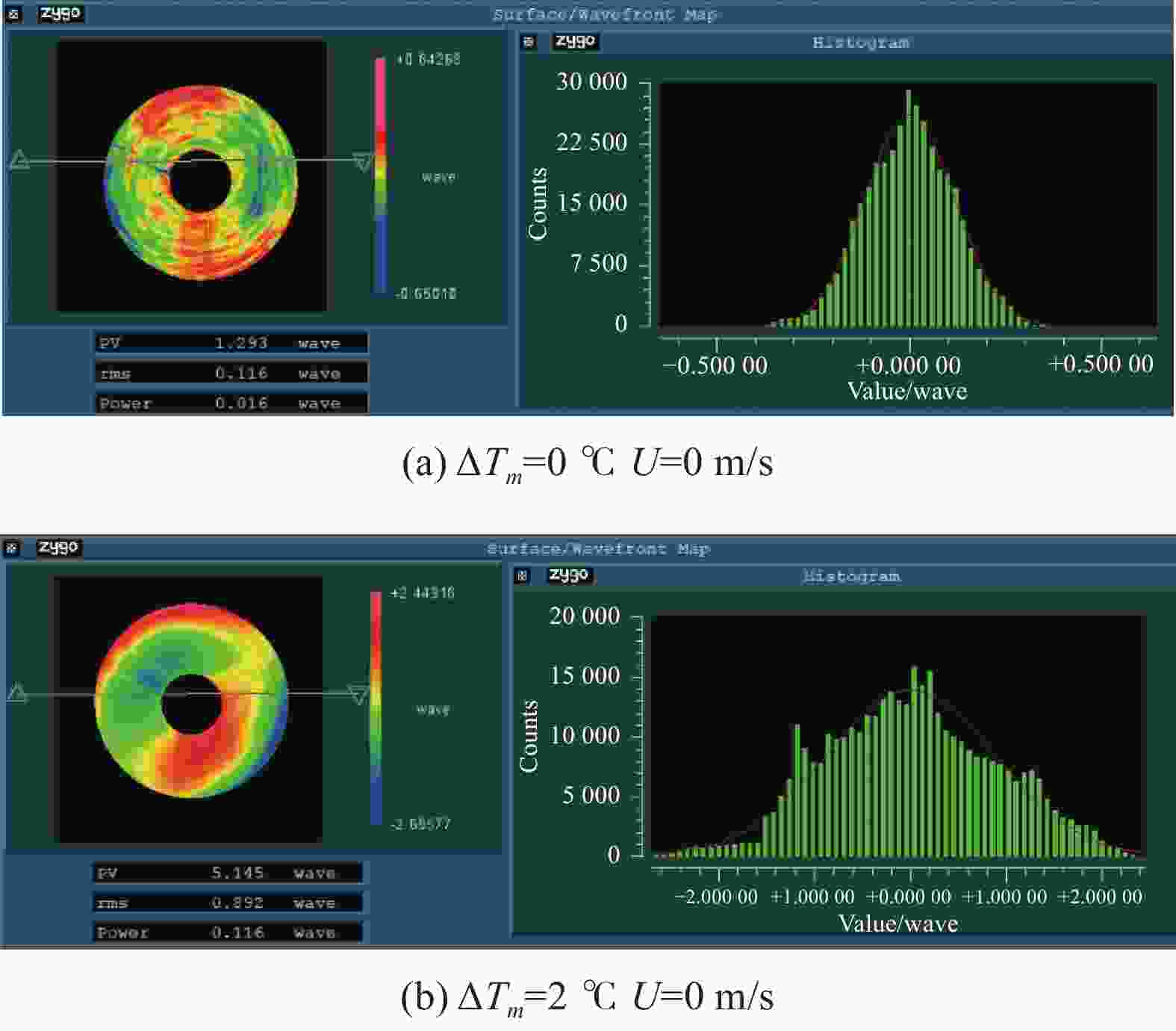
图 7 ɸ1.55 m大口径双曲面反射镜实验结果图
Figure 7. Test result diagram of ɸ1.55 m large hyperboloid reflector primary mirror
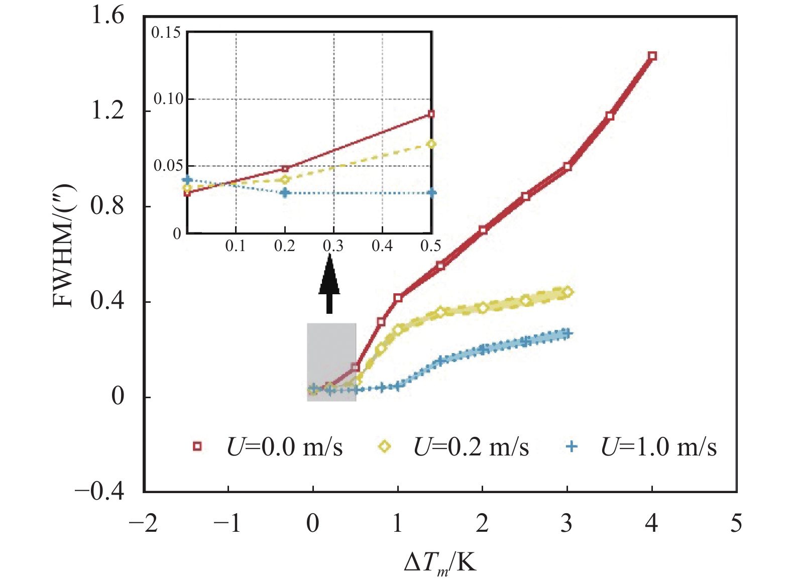
文中分别对自然对流和强迫对流的实验结果总结,其结果如表2和表3、4所示。表2、3中,在自然对流和低风速(U=0.2 m/s)的强迫对流时,随着镜面温度和周围空气的温差变大,镜面视宁度逐渐变大。表4中,在高风速(U=1.0 m/s)的强迫对流时,将镜面视宁度的变化分为两种情况:首先,镜面温差$ {\mathrm{\Delta }T}_{m} $小于1 ℃时,镜面视宁度没有稳定的变化曲线,局部出现较小幅下降趋势,且温差是0 ℃,其镜面视宁度大于其他两种情况;其次,温差$ {\mathrm{\Delta }T}_{m} $大于1 ℃时,镜面视宁度随吹风气流风速增大而减小。结合图8、9可以看出,镜面视宁度的变化斜率逐渐变大,温差$ {\mathrm{\Delta }T}_{m} $大于2 ℃时,变化斜率趋于稳定。
表 2 自然对流条件下(镜面风速U=0 m/s)实验数据总结
Table 2. Summary of test results for free convection (Mirror velocity=0 m/s)
Model Mirror velocity/m·s−1 $ {\Delta T}_{m} $/℃ $ {r}_{0} $/cm Strehl ratio FWHM/(″) Free convection U=0 0 20.67 0.98 0.03 0.2 12.40 0.97 0.05 0.5 4.77 0.88 0.13 0.8 1.94 0.71 0.32 1 1.48 0.62 0.42 1.5 1.13 0.51 0.55 2 0.89 0.40 0.70 2.5 0.74 0.31 0.84 3 0.64 0.22 0.97 3.5 0.55 0.17 1.18 4 0.43 0.15 1.43 表 3 低风速的强迫对流条件下(镜面风速U=0.2 m/s)实验数据总结1)公式适用于$ {\mathrm{\Delta }T}_{m} $>0 ℃
Table 3. Summary of test results for forced convection at low wind speed (Mirror velocity=0.2 m/s) 1) the formula is applicable to $ {\mathrm{\Delta }T}_{m} $>0 ℃
Model Mirror velocity/m·s−1 $ {\Delta T}_{m} $/℃ $ {r}_{0} $/cm Strehl ratio FWHM/(″) $ {F}_{r} $ Forced convection U=0.2 0 18.51 0.98 0.03 \ 1) 0.2 15.60 0.97 0.04 0.18 0.5 8.86 0.92 0.07 0.36 0.8 2.99 0.78 0.21 0.18 1 2.18 0.72 0.28 0.22 1.5 1.75 0.62 0.36 0.40 2 1.65 0.59 0.38 0.84 2.5 1.52 0.54 0.41 1.39 3 1.41 0.50 0.44 1.92 表 4 高风速的强迫对流条件下(镜面风速U=1.0 m/s)实验数据总结1)公式适用于$ {{\Delta }T}_{m} $>0 ℃
Table 4. Summary of test results for forced convection at high wind speed (Mirror velocity=1.0 m/s) 1) the formula is applicable to $ {{\Delta }T}_{m} $>0 ℃
Model Mirror velocity/m·s−1 $ {\Delta T}_{m} $/℃ $ {r}_{0} $ /cm Strehl ratio FWHM/(″) $ {F}_{r} $ Forced
convectionU=1.0 0 15.38 0.94 0.04 \ 1) 0.2 21.46 0.96 0.03 0.06 0.5 18.75 0.96 0.03 0.92 0.8 14.61 0.94 0.04 4.23 1 12.66 0.91 0.05 2.93 1.5 4.04 0.89 0.15 6.63 2 3.07 0.83 0.20 6.77 2.5 2.64 0.79 0.24 8.84 3 2.30 0.74 0.27 10.8 
图 8 1550 mm镜面斯特尔比随镜面-空气温差变化曲线(图中填充部分是多组实验数据的误差统计结果)
Figure 8. Strehl Intensity as a function of mirror-air temperature difference for the 1550 mm mirror (The filled portion of the figure shows the error statistics for multiple sets of experimental data)
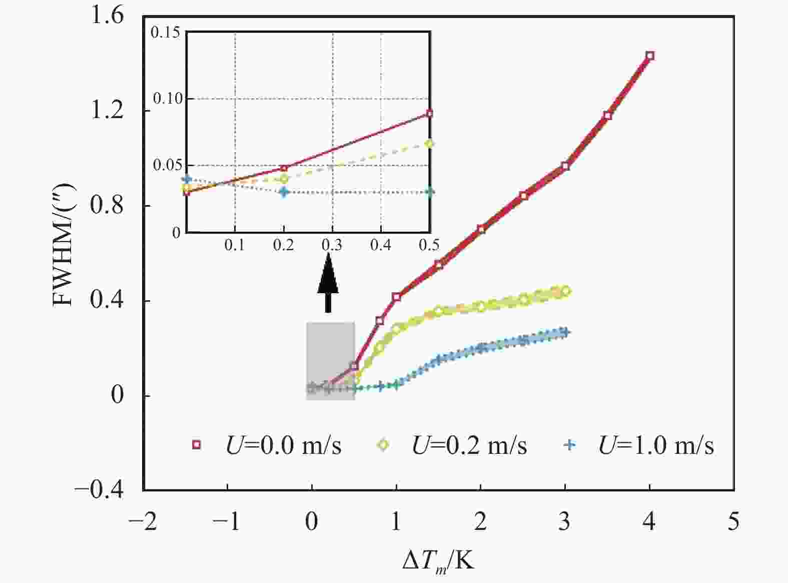
图 9 1550 mm镜面的镜面视宁度半高全宽随镜面-空气温差变化的曲线(图中填充部分是多组实验数据的误差统计结果)
Figure 9. FWHM as a function of mirror-air temperature difference for the 1550 mm mirror (The filled portion of the figure shows the error statistics for multiple sets of experimental data)
实验结果表明:镜面视宁度与镜面温差有关,镜面附近自然对流与外部强迫气流的相互作用,存在一个预期稳定到不稳定的转变。强迫吹风使得镜面附近产生微小空气分子运动,即使是尺度较小的乱流运动,镜面视宁度也会产生非常敏感的变化。
在强迫对流的条件下,镜面温差$ {\mathrm{\Delta }T}_{m} $较小时,由外部气流主导镜面附近空气运动;温差$ {\mathrm{\Delta }T}_{m} $较大时,镜面对流会一边随外部气流迁移,一边受到其湍流的搅扰,表现为完全随机的湍流状态流动。由于镜面温度高于周围空气,引起镜面上方的弱混合对流,大气密度或温度的随机波动引发折射场湍动,导致粘性导电层上方的一个薄区域产生镜面视宁度,其温度波动最大且具有随机性。
由镜面视宁度研究结果可知,镜面温差和环境风速与镜面视宁度效应相关性强。根据中国巨型太阳望远镜(CGST)的主镜视宁度效应误差标准,文中将在镜面视宁度效应作用下可见光波段的衍射极限分辨率达到0.05″作为分析标准。结合表2~4和图9,在弱混合对流条件下(U=0.2 m/s),镜面-空气温差应控制在0.2 K以下;在强混合对流条件(U=1.0 m/s),镜面-空气温差应控制在1 K以下。
-
自然对流的大气状态下,当镜面温度高于环境温度时,镜面视宁度seeing和镜面温差 $ {\mathrm{\Delta }T}_{m} $呈正比的变化趋势。镜面视宁度和镜面温差之间的关系表示为[18]:
$$ \theta =\alpha \cdot {{\mathrm{\Delta }T}_{m}}^{1.2} $$ (10) 式中:$ \alpha $ 为镜面视宁度系数。
实验中,为了研究温差变化和镜面视宁度系数两者的相关性变化,对系数按照温差从小到大顺序进行拟合。根据实验结果拟合出模型经验公式,镜面温差较大时表示为:
$$ \theta =0.25\cdot {{\mathrm{\Delta }T}_{m}}^{1.2}$$ (11) 镜面温差较小时表示为:
$$ \theta =0.45\cdot {{\mathrm{\Delta }T}_{m}}^{1.2} $$ (12) 如图10所示,分析结果包含所有的实验数据。

图 10 自然对流条件下镜面视宁度随镜面-空气温差变化的曲线
Figure 10. Seeing as a function of mirror-air temperature difference for free convection
-
通过增加外部气流可以降低镜面附近的大气湍流,减小镜面视宁度,使用弗劳德数$ {F}_{r} $来量化评估强制通风的效果。在任何给定的气流速度下,$ {F}_{r} $表示为:
$$ {F}_{r}=\frac{T{{{U}}}^{2}}{\Delta TgD}$$ (13) 式中:D为镜面直径。
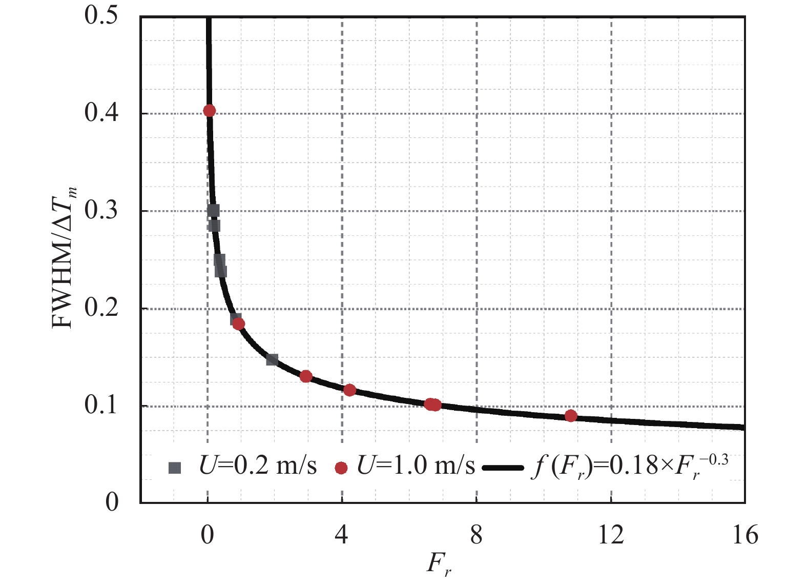
FWHM(θ)和 $ {{\Delta }T}_{m} $呈近似的线性关系,采用统计分析的方法,建立了镜面视宁度、镜面温差和$ {F}_{r} $的关系式,归一化后表示为:
$$ \frac{\theta }{\Delta {T}_{m}}=f\left({F}_{r}\right)$$ (14) 根据1550 mm双曲面镜的实验结果,计算的关于$ {F}_{r} $的公式与上式相符,如图11所示,规律性公式为:
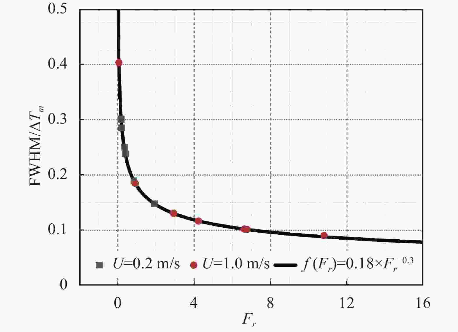
图 11 强迫对流条件下 FWHM/$\Delta {T}_{m} $随弗劳德数$ {F}_{r} $变化的曲线
Figure 11. FWHM/$ \Delta {T}_{m} $ as a function of the Froude number for forced convection
$$ f\left({F}_{r}\right)=0.18\cdot {{F}_{r}}^{-0.3} $$ (15) 把公式(16)代入公式(15)得到:
$$ \frac{\theta }{\Delta {T}_{m}}=0.18\cdot {{F}_{r}}^{-0.3} $$ (16) 由公式(14)和公式(17),推导出强迫通风下镜面视宁度的尺度分析公式,表示为:
$$ {\lambda }_{\theta }={\lambda }_{\Delta T}\cdot {\lambda }_{{F}_{r}}^{-0.3}={\lambda }_{\Delta T}{\left(\frac{{\lambda }_{{\rm{U}}}^{2}}{{\lambda }_{\Delta T}\cdot {\lambda }_{D}}\right)}^{-0.3} $$ (17) 式中:$ {\lambda }_{\theta } $为镜面视宁度无量纲分析量,得到:
$$ {\lambda }_{\theta }={{\lambda }_{\Delta T}}^{1.3}{{\cdot \lambda }_{{\rm{U}}}}^{-0.6}\cdot {{\lambda }_{D}}^{0.3} $$ (18) 式中:$ {\lambda }_{D} $为镜面直径的无量纲分析尺度。
$ {\lambda }_{\theta } $和$ {\lambda }_{D} $的近似于正比关系,在相同的通风量时,镜面尺寸越大,镜面视宁度变大。
-
由于太阳辐射的影响,太阳望远镜主镜镜面温度高于周围空气,引起镜面上方的混合对流。大气密度或温度的随机波动引发折射场湍动,其温度波动最大且具有随机性,导致在镜面粘性导电层上方的薄区域中产生镜面视宁度效应(Mirror Seeing Effect)。
该研究聚焦于大口径太阳望远镜共性问题—镜面局部视宁度对望远镜像质退化影响规律,从大气光学湍流的角度分析镜面大气湍流过程,总结并简化实验数据,进一步分析其对望远镜像质造成的影响,从而推导出经验公式。为提升望远镜工作分辨率奠定基础,此工作也将为8 m中国巨型太阳望远镜(CGST)的建造与观测提供必要的前期研究基础。
Experiment study on large solar telescope mirror seeing
-
摘要: 太阳望远镜内部因太阳辐射作用使镜面升温,镜面上方产生局部大气湍流,导致镜面视宁度不佳,从而造成像质的严重衰减。文中基于温度梯度和气体流动导致固体-流场的耦合作用,提出镜面视宁度效应的形成机制,建立湍流大气光学产生镜面视宁度效应的理论,利用1 550 mm大口径双曲面镜的实验数据推导并验证镜面视宁度的实验模型,并对太阳望远镜主镜温控目标进行确定。在自然对流和强迫对流两种条件下,不同环境风速时镜面温差改变对镜面视宁度的影响。结果表明:镜面温差和环境风速与镜面视宁度相关性很强,增加主动通风可以降低镜面视宁度。温差是4 ℃条件下,自然对流时镜面视宁度为 1.43″;温差是 3 ℃条件下,0.2 m/s 强迫对流时镜面视宁度为 0.44″,1 m/s 强迫对流时镜面视宁度为 0.27″。根据镜面视宁度效应容差标准,在0.2 m/s强迫对流条件下,镜面-空气温差应控制在0.2 K以下;在1.0 m/s强迫对流条件下,镜面-空气温差应控制在1 K以下。此研究成果旨在揭示空气湍流的形成机理与传播规律及其对望远镜像质退化影响规律,为提升大口径太阳望远镜工作分辨率奠定基础。Abstract:
Objective The primary mirrors of large solar telescopes are continuously affected by solar radiation, causing the mirror surface temperature to be higher than the air temperature. Under the action of the temperature difference between the mirror surfaces, the air near the mirror surface is heated, causing the air density to be unevenly divided, resulting in abnormal atmospheric refraction, resulting in mirror seeing, which degrades the image quality of the solar telescope. Solar telescopes mostly use Gregorian optical systems, and their primary mirrors are aspherical mirrors. Foreign experimental research mainly uses plane mirrors or spherical mirrors for experiments. However, due to factors such as mirror surface shape, effective aperture and experimental optical path, the theoretical relevance of the experimental results is low. Mirror seeing is the coupling effect between the mirror and the surrounding air. Only numerical simulations have been carried out in China, and no relevant experimental research has been conducted on mirror seeing. Direct experimental detection is a more reliable solution. In order to control the near-mirror seeing caused by the temperature increase of the primary mirror, the mirror temperature control target needs to be given quantitatively. The main mirrors of large-aperture solar telescopes mostly use aspherical mirrors. The experimental platform of this article uses a 1 550 mm diameter hyperbolic mirror for research to improve the universality of the experimental results. Methods First, based on the solid-flow field coupling caused by temperature gradient and gas flow, this paper proposes the formation mechanism of the specular seeing effect and establishes the theory of the specular seeing effect caused by atmospheric optical turbulence. Then, based on the physical process of atmospheric turbulence producing mirror seeing, under two conditions of natural convection and forced convection (Fig.1), an experiment for a 1 550 mm large-diameter hyperbolic mirror was built (Fig.3), and the experimental data (Tab.2-4), analyze the effect of the temperature difference between the mirror surface and the surrounding air on the mirror seeing under different wind speed conditions (Fig.8-9). Finally, the experimental models under different convection conditions are summarized (Fig.10-11), and the solar telescope temperature control target is determined. Results and Discussions Experimental results show that mirror seeing is related to the mirror temperature difference. The interaction between natural convection and external forced airflow near the mirror has a transition from expected stability to instability. Forced blowing causes tiny air molecules to move near the mirror. Even small-scale turbulent movements can cause very sensitive changes in mirror seeing. Mirror temperature difference and wind speed have a strong correlation with mirror seeing (Fig.8-9). Increasing active ventilation can reduce mirror seeing. When the temperature difference is 4 ℃, the mirror seeing under natural convection is 1.43″; when the temperature difference is 3 ℃, the mirror seeing under 0.2 m/s forced convection is 0.44″, and when the temperature difference is 1 m/s forced convection, the mirror seeing is 0.27″. According to the mirror seeing effect tolerance standard, combined with Tab.2-4 and Fig.9, under weak mixed convection conditions (U=0.2 m/s), the mirror-air temperature difference should be controlled below 0.2 K; in Under strong mixed convection conditions (U=1.0 m/s), the mirror-air temperature difference should be controlled below 1 K. Conclusions Due to the influence of solar radiation, the temperature of the main mirror of the solar telescope is higher than that of the surrounding air, causing mixed convection above the mirror. Random fluctuations in atmospheric density or temperature trigger turbulence in the refractive field, with the temperature fluctuation being the largest and random, resulting in a mirror seeing effect in the thin area above the specular viscous conductive layer. This article starts from the theory of atmospheric optical turbulence and combines the experimental data of the 1 550 mm hyperboloid primary mirror under different convection conditions to study the quantitative relationship between mirror temperature rise and telescope observation image quality, providing a research basis for setting the temperature control target of the solar telescope's primary mirror. This study focuses on the common problem of large solar telescopes - the influence of the mirror seeing on the degradation of the telescope image quality. It analyzes the atmospheric turbulence process of the mirror from the perspective of atmospheric optical turbulence, summarizes and simplifies the experimental data, and further analyzes its impact on the telescope image. The influence caused by quality is derived from the empirical formula. In order to lay the foundation for improving the working resolution of the telescope, this work will also provide the necessary preliminary research foundation for the construction and observation of the 8-meter China Giant Solar Telescope (CGST). -
Key words:
- atmospheric optics /
- mirror seeing /
- atmospheric turbulence /
- solar telescope /
- froude number
-
图 2 FWHM与Strehl Intensity之间的关系
Figure 2. Relationship between FWHM and Strehl Intensity
图 5 系统总体布局(图中空心圆圈是贴片式温度传感器和空气温度传感器;空心圆柱是超声波风向风速传感器;红色长方形是硅橡胶加热板;梯形是电风扇)
Figure 5. System overall layout (The hollow circles are SMD temperature sensors and air temperature sensors; the hollow cylinder is the ultrasonic wind direction and speed sensor; the red rectangle is the silicone rubber heating plate; the trapezoid is the electric fan)
图 6 自然对流时温度传感器随时间变化的曲线
Figure 6. Temperature sensors curve with time for free convection
图 7 ɸ1.55 m大口径双曲面反射镜实验结果图
Figure 7. Test result diagram of ɸ1.55 m large hyperboloid reflector primary mirror
图 8 1550 mm镜面斯特尔比随镜面-空气温差变化曲线(图中填充部分是多组实验数据的误差统计结果)
Figure 8. Strehl Intensity as a function of mirror-air temperature difference for the 1550 mm mirror (The filled portion of the figure shows the error statistics for multiple sets of experimental data)
图 9 1550 mm镜面的镜面视宁度半高全宽随镜面-空气温差变化的曲线(图中填充部分是多组实验数据的误差统计结果)
Figure 9. FWHM as a function of mirror-air temperature difference for the 1550 mm mirror (The filled portion of the figure shows the error statistics for multiple sets of experimental data)
图 10 自然对流条件下镜面视宁度随镜面-空气温差变化的曲线
Figure 10. Seeing as a function of mirror-air temperature difference for free convection
图 11 强迫对流条件下 FWHM/$\Delta {T}_{m} $随弗劳德数$ {F}_{r} $变化的曲线
Figure 11. FWHM/$ \Delta {T}_{m} $ as a function of the Froude number for forced convection
表 1 设备参数表
Table 1. Equipment parameter list
Species Parameter 4D interferometer Diameter: 9 mm; Focal length: 14 mm
Working band: 632.8 nmCompensating mirror set Diameter: 82 mm; Material: H-K9L
Flat 1 curvature radius: −154.88 mm
Flat 2 curvature radius: −325.9 mm
Distance between mirrors: −27.506 mmLarge hyperboloid reflector primary mirror Diameter: 1550 mm; Off-axis distance: 1500 mm
Material: glass-ceramic; Coating:enhanced aluminumFlat mirror Diameter: 1800 mm; RMS: λ/40 (632.8 nm)
Material: glass-ceramic 下载: 导出CSV
表 2 自然对流条件下(镜面风速U=0 m/s)实验数据总结
Table 2. Summary of test results for free convection (Mirror velocity=0 m/s)
Model Mirror velocity/m·s−1 $ {\Delta T}_{m} $/℃ $ {r}_{0} $/cm Strehl ratio FWHM/(″) Free convection U=0 0 20.67 0.98 0.03 0.2 12.40 0.97 0.05 0.5 4.77 0.88 0.13 0.8 1.94 0.71 0.32 1 1.48 0.62 0.42 1.5 1.13 0.51 0.55 2 0.89 0.40 0.70 2.5 0.74 0.31 0.84 3 0.64 0.22 0.97 3.5 0.55 0.17 1.18 4 0.43 0.15 1.43
下载: 导出CSV
表 3 低风速的强迫对流条件下(镜面风速U=0.2 m/s)实验数据总结1)公式适用于$ {\mathrm{\Delta }T}_{m} $>0 ℃
Table 3. Summary of test results for forced convection at low wind speed (Mirror velocity=0.2 m/s) 1) the formula is applicable to $ {\mathrm{\Delta }T}_{m} $>0 ℃
Model Mirror velocity/m·s−1 $ {\Delta T}_{m} $/℃ $ {r}_{0} $/cm Strehl ratio FWHM/(″) $ {F}_{r} $ Forced convection U=0.2 0 18.51 0.98 0.03 \ 1) 0.2 15.60 0.97 0.04 0.18 0.5 8.86 0.92 0.07 0.36 0.8 2.99 0.78 0.21 0.18 1 2.18 0.72 0.28 0.22 1.5 1.75 0.62 0.36 0.40 2 1.65 0.59 0.38 0.84 2.5 1.52 0.54 0.41 1.39 3 1.41 0.50 0.44 1.92
下载: 导出CSV
表 4 高风速的强迫对流条件下(镜面风速U=1.0 m/s)实验数据总结1)公式适用于$ {{\Delta }T}_{m} $>0 ℃
Table 4. Summary of test results for forced convection at high wind speed (Mirror velocity=1.0 m/s) 1) the formula is applicable to $ {{\Delta }T}_{m} $>0 ℃
Model Mirror velocity/m·s−1 $ {\Delta T}_{m} $/℃ $ {r}_{0} $ /cm Strehl ratio FWHM/(″) $ {F}_{r} $ Forced
convectionU=1.0 0 15.38 0.94 0.04 \ 1) 0.2 21.46 0.96 0.03 0.06 0.5 18.75 0.96 0.03 0.92 0.8 14.61 0.94 0.04 4.23 1 12.66 0.91 0.05 2.93 1.5 4.04 0.89 0.15 6.63 2 3.07 0.83 0.20 6.77 2.5 2.64 0.79 0.24 8.84 3 2.30 0.74 0.27 10.8
下载: 导出CSV
-
[1] Zhu Jiakang, An Qichang, Yang Fei. Review on the measurement methods of mirror seeing of large-aperture telescope [J]. Infrared and Laser Engineering, 2023, 52(2): 20220488. (in Chinese) doi: 10.3788/IRLA20220488 [2] Hu Xiaochuan, He Yehuan, Wu Shuang, et al. Effect of axial wind speed in inner propagation channel on phase characteristics of high-power lasers [J]. Infrared and Laser Engineering, 2016, 45(8): 0806003. (in Chinese) doi: 10.3788/IRLA201645.0806003 [3] Lowne C M. An investigation of the effects of mirror temperature upon telescope seeing [J]. MNRAS, 1979, 188(2): 249-259. doi: 10.1093/mnras/188.2.249 [4] Iye M, Noguchi T, Torii Y, et al. Evaluation of seeing on a 62 cm mirror [J]. PASP, 1991, 103: 712-722. doi: 10.1086/132870 [5] Lorenzo Z. The effect of the local atmospheric environment on astronomical observations[D]. Lausanne: École Polytechnique Fédérale de Lausanne, 1995. [6] An Qichang, Wu Xiaoxia, Zhang Jingxu, et al. Detection method of mirror seeing based on curvature/slope hybrid sensing [J]. Infrared and Laser Engineering, 2021, 50(7): 20200419. (in Chinese) doi: 10.3788/IRLA20200419 [7] Huang Shanjie, Li Zhi, Xu Jun, et al. Design of the LCS for the 1 m infrared solar telescope of the Yunnan Observatory [J]. ART (Astronomical Research & Technology), 2010, 7(4): 344-354. [8] Zhang E P, Cui X Q, Li G P, et al. Preliminary numerical simulation of mirror seeing for the Chinese Future Giant Telescope [J]. Research in Astronomy and Astrophysics, 2016, 16(6): 98. [9] Liu Yangyi. Research on active temperature control technology for large aperture ground-based solar telescopes [D]. Chengdu: Graduate School of Chinese Academy of Sciences(Institute of Optics and Electronics), 2016.du: Graduate School of Chinese Academy of Sciences (Institute of Optics and Electronics, Chinese Academy of Sciences), 2016. (in Chinese) [10] Liu Xiangyi, Wang Zhichen, Wang Zhi. Dome design of large ground-based telescope [J]. Optics and Precision Engineering, 2022, 30(23): 3031-3038. (in Chinese) doi: 10.37188/OPE.20223023.3031 [11] Liu Z, Deng Y Y, Yang D H, et al. Chinese giant solar telescope [J]. Sci Sin-Phys Mech Astron, 2019, 49: 059604. (in Chinese) doi: 10.1360/SSPMA2018-00314 [12] Guo Yiming, Wu Xiaoqing, Qing Chun, et al. Calculation of near-surface atmospheric optical turbulence parameter based on MAD optical flow [J]. Acta Optica Sinica, 2022, 42(24): 2401006. (in Chinese) doi: 10.3788/AOS202242.2401006 [13] Fried D L. Limiting resolution looking down through the atmosphere [J]. J Opt Soc Am, 1966, 56(10): 1380-1384. doi: 10.1364/JOSA.56.001380 [14] Hertig J A. Modélisation des impacts de perturbations thermiques dans les basses couches de l’atmosphere [J]. IENER, 1986, N511: 134. [15] Giovannoni J M. Contribution à L'analyse de L'effet de Convection Engendré Par Un Ilot de Chaleur en Milieu Calme et Stratifié[M]. Lausanne: EPFL, 1986: 632. [16] Sarazin. Caracterisation des Proprietes Optiques de La Turbulence Atmospherique: Application AU Choix du Site du VLT de L’observatoire Europeen Austral (ESO) [M]. Marseille: Universite, 1992. [17] Sasiela R J . Electromagnetic Wave Propagation in Turbulence: Evaluation and Application of Mellin Transforms[M]. 2nd ed. Berlin: Springer, 2007. [18] Zago L, Genequand P M, Kjelberg L. Application of flexure structures to active and adaptive opto-mechanical mechanisms[C]//SPIE, 1997, 2871: 269023. -

 点击查看大图

计量
- 文章访问数: 44
- HTML全文浏览量: 8
- PDF下载量: 18
- 被引次数: 0

