


-
随着光学技术的发展与高分辨探测和成像的需求,口径大型化、面型复杂化、结构轻量化是光学元件的发展趋势之一[1]。口径大型化的表现一是单体口径的极限增大,二是拼接镜面的子孔径镜面数量增多[2]。目前国际上最大口径的单镜面光学望远镜为8 m级,更大口径的光学望远镜主镜通常采用拼接镜面技术制备[3-4]。2021年,发射升空的JWST是目前口径最大的空间光学望远镜,主镜是由18块对角距离为1.5 m的六边形铍材料子镜拼接而成的凹面镜[5-6]。欧洲南方天文台在建的欧洲极大望远镜项目(E-ELT)主镜镜面直径42 m,由984块直径为1.45 m的六边形子镜拼接而成。每一块子镜均为离轴非球面,材料为微晶玻璃Zerodur或光学玻璃ULE,要求4.5 a内完成全部光学元件的加工[7]。口径的增大和面型的复杂导致光学元件的加工难度和生产周期极大地增加,因此,缩短大口径元件的加工周期以提升制造能力已成为亟待解决的问题。
精密磨削作为大口径硬脆非球面元件的材料高效去除工序[8],磨削面形精度(Peak-Valley, PV)“形”和磨削损伤层深度“性”直接决定了后续的抛光难度与周期。目前国内外各团队在大口径光学元件的精密磨削方面已经开展了一定的工作。彭利荣等[9]针对离轴非球面加工过程中的技术和效率问题,开展了基于计算机控制的确定性加工策略研究,对离轴非球面进行铣磨后的面形精度小于5 μm。张学忱等[10]研究了非球面超精密磨削的微振动对成形精度的影响,针对Φ500 mm口径非球面获得面形精度小于4 μm。Comley等[11]在E-ELT项目中,实现了低陡度Φ1450 mm口径镜面超精密磨削后面形精度RMS优于1 μm。张志宇等[12]提出一种高精度且经济有效的变轴单点磨削策略,利用精密五轴加工中心对Φ372 mm口径高陡度离轴SiC非球面镜磨削后面形精度PV值达到7.8 μm。Suzuki等[13]研究了回转对称非球面的精密磨削设备与在位测量系统,误差补偿加工后获得了较高的面形精度和表面粗糙度。Li等[14]对Φ400 mm口径K9元件提出局部误差补偿法并建立补偿因子,磨削面形精度PV提高到3.4 μm。但实际上真正限制脆硬材料加工效率提升的是加工引起的损伤,而亚表面损伤是脆性材料机械加工中的一种主要损伤形式,优化加工参数可抑制亚表面损伤[15]。Hao等[16]研究了光学玻璃BK7磨削过程的磨削运动学和裂纹模型,对BK7元件的快速制造具有指导意义。而大口径光学元件的精密磨削除了关注面形精度提升的问题,也需要考虑损伤层深度的问题。若磨削损伤层深度较大则表面难以抛亮,且抛亮周期超长。最理想的情况是磨削面形精度和损伤层深度相差不大,这样在进行抛光修面形的同时可去除损伤层。
文中通过理论与实验交叉,研究了基于形性协同控制的大口径离轴非球面高精度磨削,阐明了大口径离轴非球面磨削的形性精度影响因素,建立了形性精度控制策略,在大口径光学元件的高效高精度加工中具有重要应用价值。
-
光学元件为Ф640 mm口径的K9离轴等厚非球面,其母镜方程如下:
$$ \left\{ {\begin{array}{*{20}{l}} {r = \sqrt {{x^2} + {y^2}} } \\ {z = \dfrac{{{{c}}{r^2}}}{{1 + \sqrt {1 - \left( {{{k}} + 1} \right){{{c}}^2}{r^2}} }}} \end{array}} \right. $$ (1) 式中:$ x $、$ y $、$ z $表示离轴非球面的面形坐标;离轴量L=700 mm;c为非球面顶点曲率,$ {{c}} = {1 \mathord{\left/ {\vphantom {1 {{R_0}}}} \right. } {{R_0}}} $;顶点曲率半径R0=9000 mm;k为非球面系数,$ {{k}} = - 1 $。
如图1所示,大口径离轴非球面的高形性精度磨削需多项工艺环节相互迭代,每项环节分别实现不同的精度收敛目标。在磨削前期主要实现面形精度的快速提升,因此,工艺环节依次为离轴非球面的粗磨成型、镜面精磨和基于检测结果反馈迭代的面形补偿精磨。在毛坯的粗磨成型过程中,为了追求大口径离轴非球面的高去除效率,采用较大的进给参数、磨削深度和磨粒粒度等,快速磨削出离轴非球面形状,面形精度PV值达到约20~50 μm。在镜面精磨过程中,通过减小进给参数、磨削深度、磨粒粒度和砂轮修整误差,优化离轴非球面磨削方法和路径,提升磨削面形精度的同时控制损伤层深度,面形精度PV值达到约10~20 μm。为了实现更高的磨削面形精度,进一步结合补偿加工法,通过对精磨后的离轴非球面进行三坐标检测,根据检测的误差分析结果补偿Z向进给量,使面形精度PV值优于5 μm。磨削后期阶段主要是减小损伤层深度和提升表面粗糙度,旨在大幅减小后续抛亮时间,通过采用树脂基砂轮与微量去除工艺参数实现,且需保持前期达到的面形精度。

图 1 镜面精密磨削工艺流程
Figure 1. Process flow of precision mirror grinding
-
磨削是一种具有较高确定性的成形加工方法,其本质是磨削工具与工件的切触形状在工件表面上沿进给路径干涉相消后的残余包络面。因此,磨削面形精度误差主要受机床、磨削工具、工具与工件的相对位置精度以及磨削工艺参数选取等因素影响。在精磨阶段为了追求高的磨削精度,需要对上述影响因素进行确定性分析、控制和补偿。
-
大口径离轴非球面光学元件的高精度磨削设备一般包含X、Y、Z方向直线运动轴、工件回转台、磨削主轴以及工件/工具摆动轴。1 m口径以内的机床,摆动轴通常设计为摇篮结构以带动工件回转台摆动,而超过1 m口径的机床摆动轴通常设计为带动磨削主轴摆动的结构。对文中Φ640 mm口径离轴非球面实验件,研究采用OptoTech MCG 500 CNC-Compact高精度5轴数控铣磨机,各数控轴的定位与重复定位精度见表1,磨削设备与实验状态如图2所示。
表 1 各数控轴定位及重复定位精度
Table 1. Positioning accuracy and repeated positioning accuracy of the CNC grinding machine
Axis X/μm Y/μm Z/μm A/(″) C/ ('') Positioning accuracy ≤5 ≤5 ≤5 ≤9 ≤7 Repeated positioning accuracy ±2 ±2 ±2 ±5 ±5 
图 2 磨削设备示意图
Figure 2. Illustration of grinding machine
离轴非球面的磨削方法有螺旋磨削法和光栅磨削法两种,根据磨削点处砂轮旋转线速度与工件旋转线速度方向的相对位置为平行和垂直的关系,又各分为平行磨削法和垂直磨削法。对该离轴非球面磨削采用如图3所示的垂直磨削法。

图 3 非球面垂直磨削示意图
Figure 3. Illustration of aspherical vertical grinding
-
A轴的理想零位可保证C轴回转中心与X、Y直线运动轴所在平面的垂直度。当A轴的零位出现偏差时,就会影响离轴非球面元件的磨削离轴角误差,进而影响面形精度。因此,依据非球面方程(公式(1)),对A轴零位误差对面形精度的影响规律进行分析。其中,离轴角计算公式为:
$$ \theta = \arctan \left( {\frac{{{z_{{\text{far}}}} - {z_{{\text{near}}}}}}{D}} \right) $$ (2) 式中:$ {z_{{\text{far}}}} $、$ {z_{{\text{near}}}} $分别表示离轴非球面远、近端z坐标;$ \Delta \theta $为$ \theta $角的误差变化量。非球面坐标绕X轴旋转变换:
$$ \left[ {\begin{array}{*{20}{c}} x \\ y \\ z \end{array}} \right] = \left[ {\begin{array}{*{20}{c}} 1&0&0 \\ 0&{\cos \left( {\theta + \Delta \theta } \right)}&{\sin \left( {\theta + \Delta \theta } \right)} \\ 0&{ - \sin \left( {\theta + \Delta \theta } \right)}&{\cos \left( {\theta + \Delta \theta } \right)} \end{array}} \right]\left[ {\begin{array}{*{20}{c}} x \\ y \\ z \end{array}} \right] $$ (3) 根据上式,分析A轴零位误差从0.001°~0.01°的变化范围带来的理论面形精度PV偏差,结果如图4所示,面形精度PV随A轴角增量呈线性变化,$ \Delta \theta = {0.001^ \circ } $时,PV变化5.50 μm。
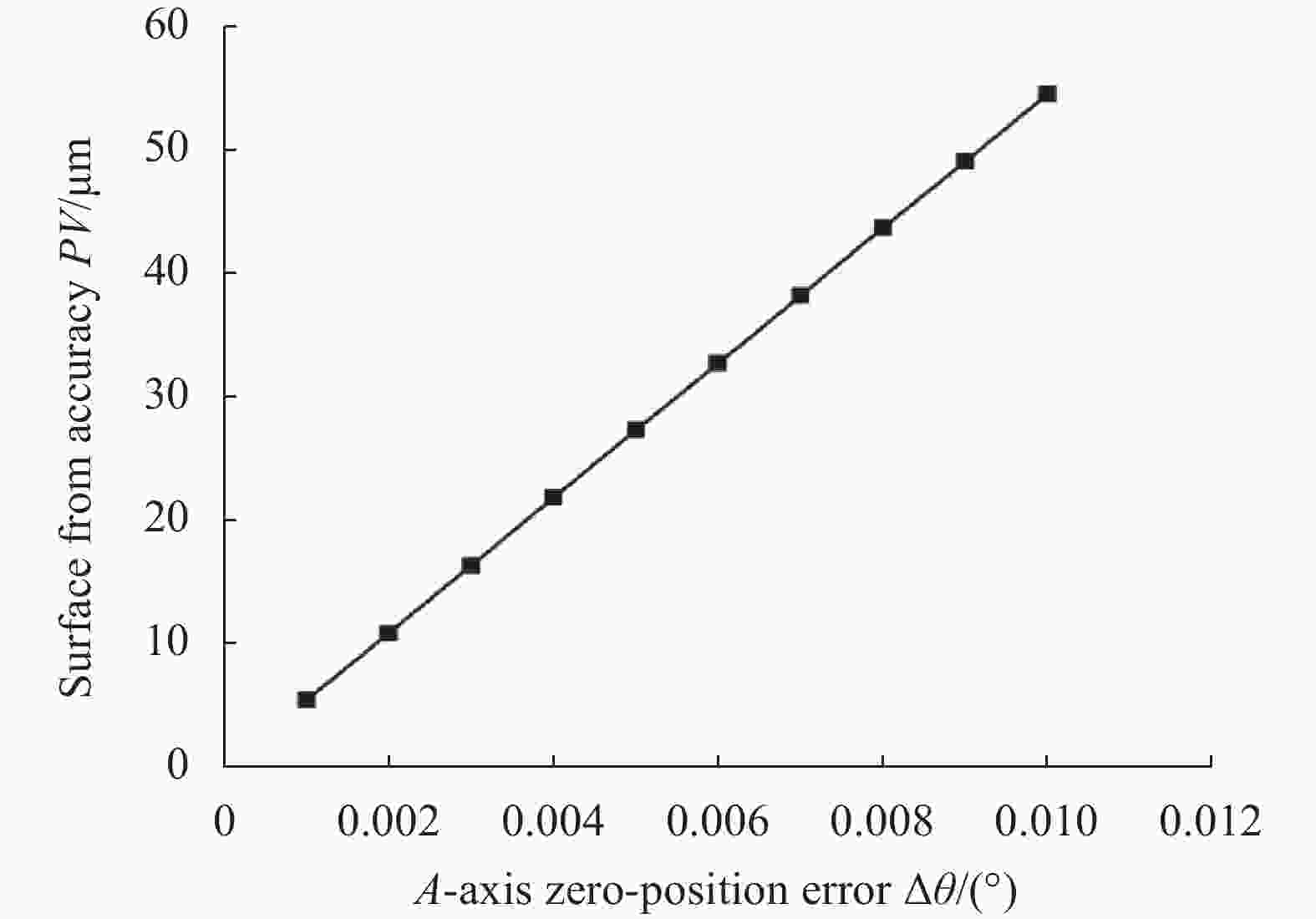
图 4 A轴零位误差对面形精度PV的影响
Figure 4. Effect of A-axis zero-position error on surface form accuracy (PV)
以表2中磨削工艺参数开展验证实验,A轴零位前后变化为0.001°,铣磨前后利用海克斯康GlobalAchangtage152210三坐标对A轴零位变化前后磨削面形进行检测,如图5所示,拟合分析后的面形精度PV分别为51.50 μm和44.60 μm,PV值变化了6.90 μm,与理论计算变化量5.50 μm接近。
表 2 螺旋路径磨削工艺参数
Table 2. Grinding parameters with spiral scanning-path
Grinding
pathGrinding
depth/
μmWorkpiece
rotary speed/
r·min−1Feed
rate/
mm·min−1Grinding
wheel rotary
speed/r·min−1Spiral 10 22 1.8 3000 -
Y轴为磨削过程中工件进给水平轴,Y轴对中误差为工件中心与机床Y轴理想零位偏差,影响离轴非球面元件的离轴量误差。为简化分析,以通过远近端两点子午截面的非球面轮廓曲线为研究对象,假设理想曲线方程为$ {f_{id}}\left( y \right) $,而实际方程为$ {f_{ac}}\left( y \right) $,则二者偏差可记为:
$$ {e_{{z}}} = {f_{{{id}}}}\left( y \right) - {f_{{{ac}}}}\left( y \right) $$ (4) 当Y轴存在对中误差时,有:
$$ \left\{ {\begin{array}{*{20}{l}} {{f_{{{ac}}}}\left( y \right) = {f_{{{id}}}}\left( {y + \Delta y} \right)} \\ {\Delta y = \cos \left( \theta \right){d_{{b}}}} \end{array}} \right. $$ (5) 式中:${d_{{b}}}$为机床Y轴对中误差,将公式(5)代入公式(4)可得:
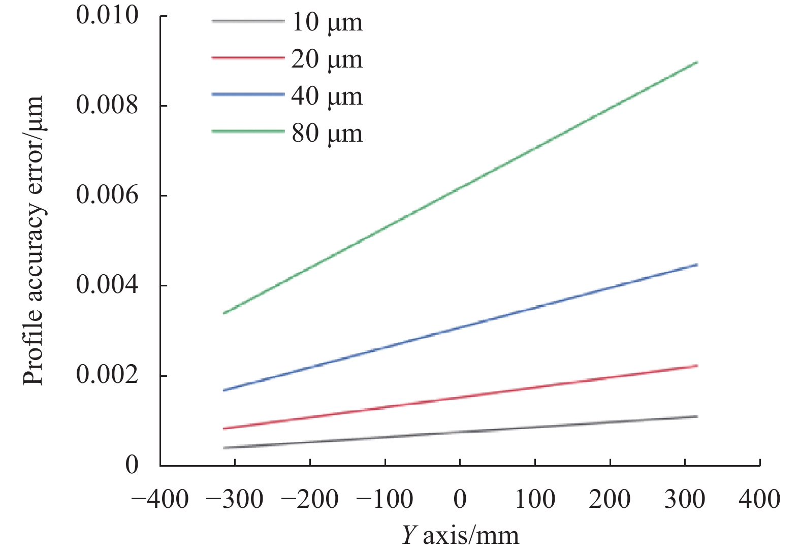
$$ {e_{{z}}} = {f_{{{id}}}}\left( y \right) - {f_{{{id}}}}\left( {y + \cos \left( \theta \right){d_{{b}}}} \right) $$ (6) 根据上式,仿真分析Y轴对中误差由10~80 μm的范围带来的理论面形精度变化,结果如图6所示,面形精度沿Y轴方向呈线性变化,但最大变化量小于10 μm,误差敏感度较弱。

图 5 面形精度PV实验结果。(a) $\Delta \theta = {0^ \circ }$;(b) $ \Delta \theta = {0.001^ \circ } $
Figure 5. Experimental results of the surface form accuracy (PV). (a) $\Delta \theta = $$ {0^ \circ }$; (b) $ \Delta \theta = {0.001^ \circ } $

图 6 Y轴对中误差对面形精度PV影响规律
Figure 6. Effect of Y-axis alignment error on surface form accuracy (PV)
随后,以表2中磨削参数开展验证实验,设置Y轴对中偏差为70 μm,磨削前面形精度见图5(b),磨削后面形精度如图7所示,PV降低了9 μm,与理论计算变化量7.90 μm相近。

图 7 对中偏差db=70 μm的面形精度PV
Figure 7. Y bias db=70 μm experimental results of the surface form accuracy (PV)
-
砂轮实际使用过程中因安装、测量及磨损会导致实际半径与数值半径存在偏差,对面形精度会产生一定影响,如图8所示,砂轮半径尺寸做50 μm的减小调整,该离轴非球面的面形精度PV降低了3 μm。

图 8 面形精度PV实验结果。(a) r=59.690 mm; (b) r=59.640 mm
Figure 8. Experimental results of the surface form accuracy (PV). (a) r=59.690 mm; (b) r=59.640 mm
-
不同的磨削方法与运动路径会对磨削精度产生一定影响。针对该离轴非球面镜对比了三轴联动螺旋磨削法、四轴联动螺旋磨削法和光栅磨削法对面形精度的影响。图9(a)是Y、Z和C轴三轴联动磨削加工后的面形精度,PV为12 μm,图9(b)是X、Y、Z和C四轴联动磨削后的面形精度,PV为10 μm,图9(c)是三轴光栅磨削后的面形精度,PV为6 μm,光栅磨削参数见表3。经比较,针对该离轴非球面,三轴联动的光栅磨削方式可获得最高面形精度,其次为四轴联动的螺旋磨削方式。
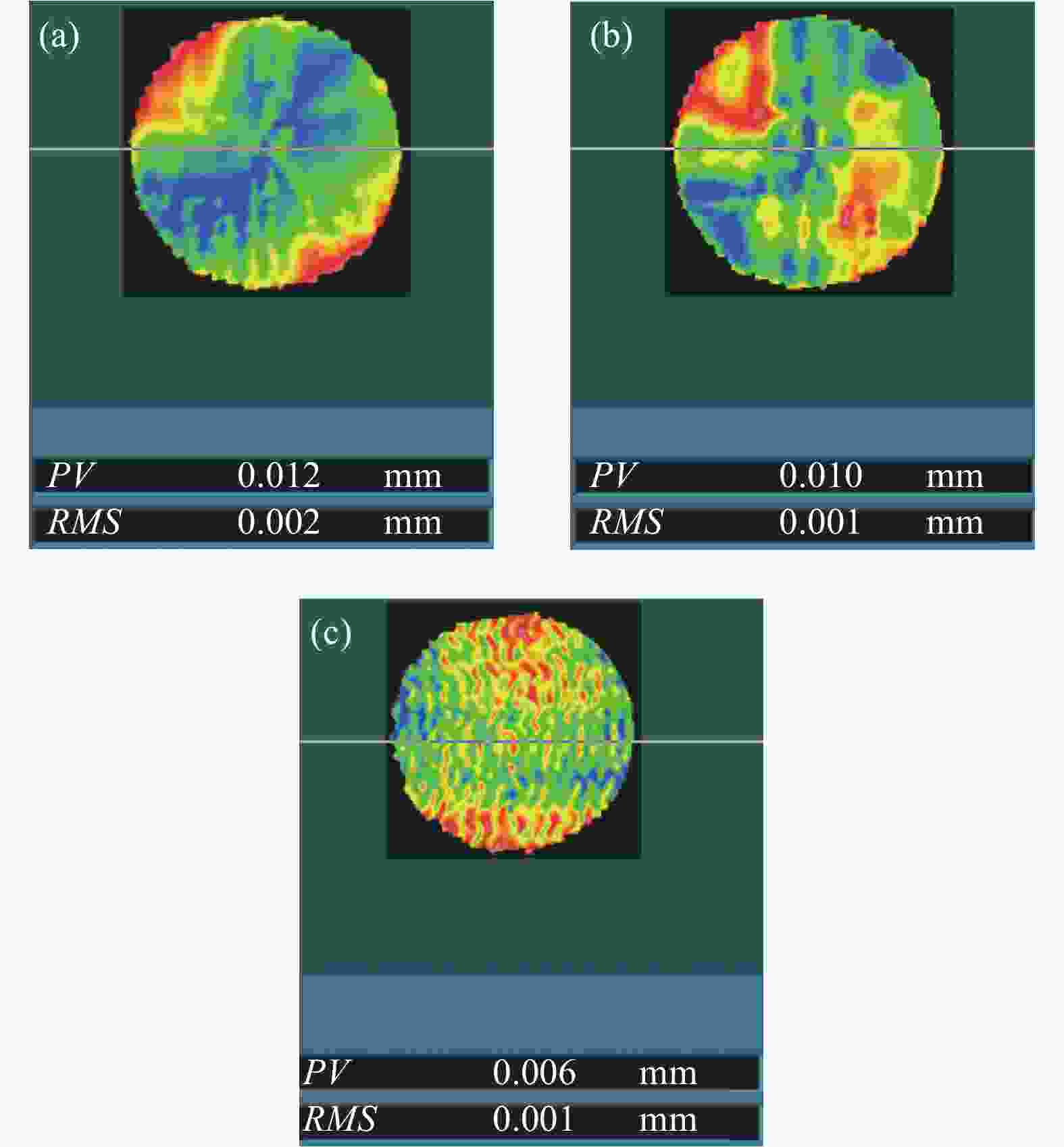
图 9 面形精度PV实验结果。(a) 三轴联动螺旋路径;(b) 四轴联动螺旋路径;(c) 三轴联动光栅路径
Figure 9. Experimental results of the surface form accuracy (PV). (a) Three-axis spiral scanning-path; (b) Four-axis spiral scanning-path; (c) Three-axis raster scanning-path
表 3 光栅路径磨削工艺参数
Table 3. Grinding parameters with raster scanning-path
Grinding
pathGrinding depth/
μmFeed speed/
mm·min−1Feed
distance/
mmGrinding
wheel rotary
speed/r·min−1Raster 10 700 0.1 3000 -
在特定的加工方法和条件下,系统会引入固有误差,采用Z轴面形精度补偿可尽可能减小这部分误差,即先对磨削后的面形精度进行精确测量,然后依据面形残余误差再进行Z轴进给量调整以实现补偿加工。如图10所示,利用金属基D20砂轮通过Z轴精度补偿加工后,面形精度PV从8 μm显著提升到3 μm,基本接近了三坐标的精度检测能力极限。

图 10 面形精度PV实验结果。(a)精度补偿前;(b)精度补偿后
Figure 10. Experimental results of the surface form accuracy (PV). (a) With-out accuracy compensation; (b) With accuracy compensation
-
磨削表层/亚表层损伤是磨削质量的一个重要体现方面,其深度直接决定了大口径元件的后续抛亮时间是数天还是数月。对亚表层损伤的精确测量通常采用破坏性的检测手段,这对大口径光学元件并不能适用。因此,针对磨削亚表层损伤的研究也多基于较小的样件开展实验,多为磨削损伤深度预测建模和磨削实验后采用截面切开抛光后的损伤状态观测。
研究前期开展了基于磨削力和表面粗糙度的亚表层损伤深度数学模型的建立工作,如图11所示。磨削力和表面粗糙度相对于亚表层损伤更容易检测,因此首先利用弹塑性力学与统计分析方法分别建立高精度的磨削力预测模型或表面粗糙度预测模型。其次,基于压痕断裂力学可建立磨削力-损伤深度的数学关系式或表面粗糙度-损伤深度的数学关系式。通过开展磨削实验,对亚表层损伤深度预测模型的系数进行确定,修正模型实现适应一类磨削参数的损伤深度高精度预测。根据模型可以代入不同磨削工艺参数对损伤深度进行预测,从而选取损伤深度小的磨削工艺参数作为加工参数。

图 11 两种损伤深度预测模型建立流程图
Figure 11. Flow chart two kinds of damage depth prediction models established
大口径元件一般加工周期要求非常短,所以很难通过耗时较长的实验设计、精确建模预测与工艺参数优化的方法来抑制磨削损伤层深度。此外,大口径元件在磨削过程中的磨削力难以实时测量,但磨削完后的表面粗糙度方便测量,所以对大口径元件磨削损伤可以通过与表面粗糙度的关系进行预估控制。在大口径元件的磨削加工中,并不追求极低的亚表层损伤深度,最为理想的状态为控制磨削面形精度与损伤层深度相近,可在后续研抛环节中进行面形修形的同时去除掉磨削损伤层。
-
基于断裂力学,亚表层损伤深度和表面粗糙度Rz分别被认为近似等同于中位裂纹深度和侧向裂纹深度,如图12所示,二者具有一定数学关系。因此,为统计亚表层损伤深度与表面粗糙度之间关系,以及随磨削参数的变化规律,设计并开展了18组实验,参数具体如表4所示。

图 12 亚表面损伤层和表面粗糙度关系
Figure 12. Relationship between subsurface damage layer and surface roughness
表 4 磨削工艺参数
Table 4. Grinding technological parameter
Group Griding
wheelGrinding
depth/μmSpindle speed/
r·min−1Feed speed/
mm·min−11 Mental
bond/D301 12000 2 2 Mental
bond/D201 12000 2 3 Resinoid
bond/D301 12000 2 4 Resinoid
bond/D201 12000 2 5 Resinoid
bond/D151 12000 2 6 Resinoid
bond/D101 12000 2 7 Mental
bond/D302 12000 2 8 Mental
bond/D303 12000 2 9 Resinoid
bond/D201 8000 2 10 Resinoid
bond/D201 10000 2 11 Resinoid
bond/D201 14000 2 12 Resinoid
bond/D201 16000 2 13 Resinoid
bond/D201 18000 2 14 Resinoid
bond/D201 12000 3 15 Resinoid
bond/D201 12000 4 16 Resinoid
bond/D201 12000 5 17 Resinoid
bond/D201 12000 6 18 Resinoid
bond/D201 12000 7 实验后,首先运用白光干涉仪对磨削表面形貌和粗糙度进行观测,然后对亚表面进行截面切开、抛光和酸蚀处理,再运用扫描电镜对亚表面裂纹进行观测。根据实验结果总结分析磨削表面形貌、表面粗糙度和亚表面损伤深度受砂轮参数、磨削深度、砂轮转速和进给速度的影响规律,如图13中对比了金属基D20砂轮、树脂基D20砂轮与树脂基D10砂轮三种工具磨削后的表面与亚表面质量。金属基D20砂轮磨削完后因表面破碎较多致使磨削纹路不明显,表面粗糙度Ra为90 nm、Rz为1.73 μm,亚表面损伤深度为20.17 μm。树脂基D20砂轮磨削完后表面磨削纹路较为清晰,破碎程度有所改善,表面粗糙度Ra为31 nm、Rz为0.50 μm,亚表面损伤深4.40 μm,均比金属基砂轮的磨削结果大幅改善。树脂基D10砂轮磨削后表面一致性好,磨削纹路变浅,表面粗糙度Ra为15 nm、Rz为0.25 μm,亚表面损伤深为2.46 μm,表面与亚表面质量又得到进一步提升。

图 13 (a)~(c)金属基D20、树脂基D20及树脂基D10砂轮磨削纹路;(d)~(f)金属基D20、树脂基D20及树脂基D10砂轮磨削表面形态及亚表面损伤
Figure 13. (a)-(c) Grinding marks after grinding with the D20 metal base, D20 resin base and D10 resin base grinding wheels; (d)-(f) Surface morphology and subsurface damage after grinding with the D20 metal base, D20 resin base and D10 resin base grinding wheels
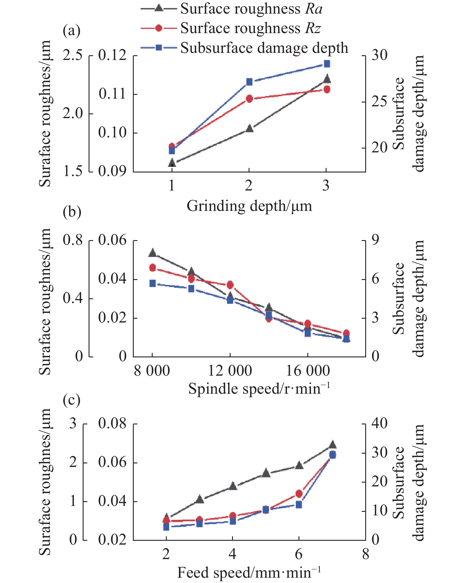
对18组实验结果进行分析,如图14和图15所示,表面粗糙度Ra和Rz数值与亚表层损伤深度随砂轮参数和磨削参数的变化规律基本一致。相较金属基砂轮,树脂基砂轮磨削后表面粗糙度和亚表层损伤深度较低,且磨粒粒度越小,表面粗糙度和亚表层损伤深度越低。因此,在磨削中可用金属基砂轮进行精密磨削实现高精度面形,用小粒度树脂基砂轮提升表面与亚表面质量。此外,磨削表面粗糙度和亚表层损伤深度随着磨削深度和进给速度的增大而增大,随着砂轮转速的增大而减小。在实际磨削中,综合平衡磨削效率与质量,前期给定较大磨削深度与进给速度提升磨削效率,后期通过减小磨削深度与进给速度提升表面与亚表面质量。

图 14 不同砂轮磨削后表面粗糙度和亚表层损伤深度
Figure 14. Surface roughness and subsurface damage depth after grinding with different grinding wheels

图 15 不同磨削深度(a)、主轴转速(b)和进给速度(c)下表面粗糙度和亚表层损伤深度
Figure 15. Surface roughness and subsurface damage depth under different grinding depth (a), spindle speed (b) and feed speed (c)
-
基于图14和图15所示的磨削损伤深度与表面粗糙度映射关系,在大口径元件加工中以磨削后表面粗糙度作为参考,预估亚表层损伤深度。对大口径元件高精度磨削面形精度PV可达5 μm以下,则最佳控制损伤深度目标与该PV一致。对3.2节中实验结果进行分析,见图16,磨削损伤深度小于5 μm时,表面粗糙度Ra小于30 nm、Rz小于0.25 μm,可作为磨削损伤控制的参考指标。

图 16 不同磨削参数下表面粗糙度和亚表层损伤深度
Figure 16. Surface roughness and subsurface damage depth under different grinding parameters
随后,对Φ640 mm口径离轴非球面镜在完成带面形精度补偿精密磨削后(金属基D20砂轮),PV达到3 μm,采用树脂基D20砂轮进行表面质量控性提升,最终测量的磨削表面粗糙度Ra小于24 nm、Rz小于0.2 μm,依照表面粗糙度与亚表面损伤层深度映射关系,亚表面损伤层深度5 μm左右,逼近面型精度PV。在磨削环节对镜面粗糙度与损伤抑制后,采用机械臂小工具进行保形去磨纹抛亮时间仅花费约32 h,较之前同等口径元件缩短了两三倍以上。
-
文中针对大口径离轴非球面磨削的形性精度协同提升问题,分别提出了基于建模与分析的控形与控性技术路线。在提升面形精度的控形方面,建立了大口径离轴非球面磨削过程中A轴零位误差与Y轴对中误差对面形精度的作用模型与影响规律,验证砂轮形状误差、磨削方法路径、Z轴面形补偿的影响作用,通过多因素校正补偿后实现高面形精度磨削;在抑制损伤深度的控性方面,阐明了损伤深度随磨削参数的影响规律,统计分析了亚表面损伤深度与表面粗糙度的映射关系,随后通过测量大口径离轴非球面磨削后表面粗糙度来预估损伤层深度,最终实现对磨削损伤深度的间接抑制。
将上述形性精度提升技术应用于Φ640 mm口径离轴非球面的磨削中,最终磨削面形精度PV达到3 μm,表面粗糙度Ra小于24 nm,Rz小于0.2 μm,依照表面粗糙度与亚表面损伤层深度对应关系,亚表面损伤层深度5 μm左右,逼近面型精度PV。经后续抛光验证,亚表面损伤得到有效抑制,磨削形性协同控制大幅缩短了大口径光学元件的抛光周期。
High precision grinding of large-aperture off-axis aspheric mirror with contour-performance controlling methodology (invited)
-
摘要: 大口径离轴非球面光学元件的应用需求呈大幅增长趋势,如空间/地基大口径望远镜、航空光电和地面跟踪瞄准装置等。同时,日益增大的元件口径和越来越短的加工周期使得高效高精度制造工艺成为大口径离轴非球面光学元件加工的核心问题。精密磨削作为大口径离轴非球面元件的材料高效去除工序,磨削面形精度(Peak-Valley, PV)和损伤层深度直接决定了后续的抛光难度与周期。因此,开展了大口径离轴非球面光学镜面的控形控性高精度磨削研究,即提升大口径离轴非球面光学元件的磨削面形精度的同时降低磨削损伤深度,实现二者在数值上的协同逼近。在控形方面,确立了机床结构方面影响低频面形形状与精度的主要影响因素,探究了A轴零位误差、Y轴对中误差、砂轮形状尺寸误差、磨削方法路径和Z轴面形补偿等因素对面形精度的影响规律以实现工艺参数的协同控制与精度优化。在控性方面,获得了磨削损伤深度随磨削参数的变化规律并建立了磨削损伤深度与磨削表面粗糙度的映射关系,提出针对大口径离轴非球面磨削亚表层损伤抑制策略。对640 mm口径离轴非球面镜进行形性控制磨削实验后,面形精度达到3 μm,表面粗糙度Ra小于24 nm,Rz小于0.2 μm,依照表面粗糙度与亚表面损伤层深度映射关系,亚表面损伤层深度5 μm左右,逼近面型精度。经验证后续抛光周期大幅缩短,对大口径光学元件的高效高精度加工具有重要参考价值。Abstract:
Objective Large Aperture Off-axis Aspherical Optical Elements (LAOAOE) have been increasingly demanded, such as space/ground-based large aperture telescopes, aerial optoelectronics or ground tracking & sighting instruments. Moreover, the requirements for the larger aperture and shorter processing cycle make it be the core problem to manufacture the large aperture off-axis aspheric optical elements with the highly efficient and high-precision manufacturing. For instance, the processing cycle for the LAOAOE with the diameter of 1 meter is required to be 2-3 months. As the highly efficient removal process for the LAOAOE, surface form accuracy and damage depth of precision grinding having directly determined the processing difficulty and processing cycle of the subsequent polishing processing. Therefore, the high precision grinding process of shape-performance control for LAOAOE are investigated in this paper. In other words, it is required to improve the surface form accuracy and reduce the depth of grinding damage, simultaneously. The numerical collaborative approximation of both items is needed to be achieved in the end. Methods In terms of the surface form control, it was identified the main factors for the machine tool structure, which affect the surface form accuracy of low-frequency surfaces. To achieve collaborative control and accuracy optimization of process parameters, the investigations were conducted to explore the influence laws between the surface shape accuracy and the A-axis zero error, Y-axis alignment error, shape and size error of grinding wheel, grinding wheel path, Z-axis surface compensation and so on. For the performance control, the influence laws between the grinding damage depth and grinding parameters were obtained, and the mapping relationship between the grinding damage depth and grinding surface roughness were established. The suppression strategy of the subsurface damage strategies for LAOAOE was proposed in the end. Results and Discussions Firstly, the form accuracy (PV) of the grinding surface was significantly affected by multiple factors. The A-axis zero error variation of 0.001° had led to the change of 5.47 μm (the theoretical value)/6.9 μm (the experimental value) in surface form accuracy (PV). The Y-axis alignment error variation of 0.07 mm had caused the change of 7.9 μm (the theoretical value)/9 μm (the experimental value) in surface form accuracy (PV). Surface form accuracy had also been significantly affected by the profile error of grinding wheel, grinding method and approach as well as the Z-axis error compensation. For the reasons as above, the improvement of grinding surface form accuracy is subject to the collaborative control and optimization of the above factors. Moreover analysis based on indentation fracture mechanics revealed that there was a corresponding relationship between the grinding subsurface damage depth and surface roughness. When the damage depth was less than 5 μm in the experiment, the surface roughness Ra was below 30 nm and Rz lower than 0.25 μm, all of which could be used as the basis to control the grinding damage. Finally, after the shape and property-controlled grinding of off-axis aspheric lens with an aperture of 640 nm, the surface form accuracy could reach 3.1 μm with the surface roughness Ra less than 24 nm, Rz lower than 0.2 μm. According to the relationship between the surface roughness and the depth of the subsurface damage, the estimated depth of damaged layer was lower than 5 μm. It was verified that the subsequent polishing duration had been significantly shortened. Conclusions For the LAOAOE, the grinding surface form accuracy can be efficiently improved by the deterministic analysis, control and compensation on the various factors affecting surface form accuracy. By mastering the mapping law between the grinding subsurface damage depth and surface roughness, the measurement on surface roughness can realize the indirect control of subsurface damage depth. Also, the combinatorial optimization of grinding process can achieve the efficient improvement and collaborative control of form property precision, which will lead to the significant reduction of polishing period for the optical elements with large aperture. It will be of great reference value for the efficient high-precision processing of optical elements with large aperture. -
图 4 A轴零位误差对面形精度PV的影响
Figure 4. Effect of A-axis zero-position error on surface form accuracy (PV)
图 5 面形精度PV实验结果。(a) $\Delta \theta = {0^ \circ }$;(b) $ \Delta \theta = {0.001^ \circ } $
Figure 5. Experimental results of the surface form accuracy (PV). (a) $\Delta \theta = $$ {0^ \circ }$; (b) $ \Delta \theta = {0.001^ \circ } $
图 6 Y轴对中误差对面形精度PV影响规律
Figure 6. Effect of Y-axis alignment error on surface form accuracy (PV)
图 7 对中偏差db=70 μm的面形精度PV
Figure 7. Y bias db=70 μm experimental results of the surface form accuracy (PV)
图 8 面形精度PV实验结果。(a) r=59.690 mm; (b) r=59.640 mm
Figure 8. Experimental results of the surface form accuracy (PV). (a) r=59.690 mm; (b) r=59.640 mm
图 9 面形精度PV实验结果。(a) 三轴联动螺旋路径;(b) 四轴联动螺旋路径;(c) 三轴联动光栅路径
Figure 9. Experimental results of the surface form accuracy (PV). (a) Three-axis spiral scanning-path; (b) Four-axis spiral scanning-path; (c) Three-axis raster scanning-path
图 10 面形精度PV实验结果。(a)精度补偿前;(b)精度补偿后
Figure 10. Experimental results of the surface form accuracy (PV). (a) With-out accuracy compensation; (b) With accuracy compensation
图 11 两种损伤深度预测模型建立流程图
Figure 11. Flow chart two kinds of damage depth prediction models established
图 12 亚表面损伤层和表面粗糙度关系
Figure 12. Relationship between subsurface damage layer and surface roughness
图 13 (a)~(c)金属基D20、树脂基D20及树脂基D10砂轮磨削纹路;(d)~(f)金属基D20、树脂基D20及树脂基D10砂轮磨削表面形态及亚表面损伤
Figure 13. (a)-(c) Grinding marks after grinding with the D20 metal base, D20 resin base and D10 resin base grinding wheels; (d)-(f) Surface morphology and subsurface damage after grinding with the D20 metal base, D20 resin base and D10 resin base grinding wheels
图 14 不同砂轮磨削后表面粗糙度和亚表层损伤深度
Figure 14. Surface roughness and subsurface damage depth after grinding with different grinding wheels
图 15 不同磨削深度(a)、主轴转速(b)和进给速度(c)下表面粗糙度和亚表层损伤深度
Figure 15. Surface roughness and subsurface damage depth under different grinding depth (a), spindle speed (b) and feed speed (c)
图 16 不同磨削参数下表面粗糙度和亚表层损伤深度
Figure 16. Surface roughness and subsurface damage depth under different grinding parameters
表 1 各数控轴定位及重复定位精度
Table 1. Positioning accuracy and repeated positioning accuracy of the CNC grinding machine
Axis X/μm Y/μm Z/μm A/(″) C/ ('') Positioning accuracy ≤5 ≤5 ≤5 ≤9 ≤7 Repeated positioning accuracy ±2 ±2 ±2 ±5 ±5  下载: 导出CSV
表 2 螺旋路径磨削工艺参数
Table 2. Grinding parameters with spiral scanning-path
Grinding
pathGrinding
depth/
μmWorkpiece
rotary speed/
r·min−1Feed
rate/
mm·min−1Grinding
wheel rotary
speed/r·min−1Spiral 10 22 1.8 3000
下载: 导出CSV
表 3 光栅路径磨削工艺参数
Table 3. Grinding parameters with raster scanning-path
Grinding
pathGrinding depth/
μmFeed speed/
mm·min−1Feed
distance/
mmGrinding
wheel rotary
speed/r·min−1Raster 10 700 0.1 3000
下载: 导出CSV
表 4 磨削工艺参数
Table 4. Grinding technological parameter
Group Griding
wheelGrinding
depth/μmSpindle speed/
r·min−1Feed speed/
mm·min−11 Mental
bond/D301 12000 2 2 Mental
bond/D201 12000 2 3 Resinoid
bond/D301 12000 2 4 Resinoid
bond/D201 12000 2 5 Resinoid
bond/D151 12000 2 6 Resinoid
bond/D101 12000 2 7 Mental
bond/D302 12000 2 8 Mental
bond/D303 12000 2 9 Resinoid
bond/D201 8000 2 10 Resinoid
bond/D201 10000 2 11 Resinoid
bond/D201 14000 2 12 Resinoid
bond/D201 16000 2 13 Resinoid
bond/D201 18000 2 14 Resinoid
bond/D201 12000 3 15 Resinoid
bond/D201 12000 4 16 Resinoid
bond/D201 12000 5 17 Resinoid
bond/D201 12000 6 18 Resinoid
bond/D201 12000 7
下载: 导出CSV
-
[1] Graves L R, Smith G A, Apai D, et al. Precision optics manufacturing and control for next-generation large telescopes [J]. Nanomanufacturing and Metrology, 2019, 2: 65-90. doi: 10.1007/s41871-019-00038-2 [2] Kim D, Choi H, Brendel T, et al. Advances in optical engineering for future telescopes [J]. Opto-Electronic Advances, 2021, 4(6): 210040. doi: 10.29026/oea.2021.210040 [3] 范文强, 王志臣, 陈宝刚, 等. 地基大口径拼接镜面主动控制技术综述[J]. 中国光学, 2020, 13(06): 1194-1208. doi: 10.37188/CO.2020-0032 Fan Wenqiang, Wang Zhichen, Chen Baogang, et al. Review of the active control technology of large aperture ground telescopes with segmented mirrors [J]. Chinese Optics, 2020, 13(6): 1194-1208. (in Chinese) doi: 10.37188/CO.2020-0032 [4] 霍银龙, 杨飞, 王富国. 大口径光学望远镜拼接镜面关键技术综述[J]. 中国光学, 2022, 15(05): 973-982. doi: 10.37188/CO.2022-0109 Huo Yinlong, Yang Fei, Wang Guofu. Overview of key technologies for segmented mirrors of large-aperture optical telescopes [J]. Chinese Optics, 2022, 15(5): 973-982. (in Chinese) doi: 10.37188/CO.2022-0109 [5] Jahnke K, Krause O, Rix H W, et al. The need for a multi-purpose, optical-NIR space facility after HST and JWST [J]. Experimental Astronomy, 2021, 51: 765-782. doi: 10.1007/s10686-021-09732-w [6] Atkinson C, Texter S, Hellekson R, et al. Status of the JWST optical telescope element [C]//Proceedings of SPIE, Space Telescopes and Instrumentation I: Optical, Infrared, and Millimeter, 2016, 6265: 62650T. [7] Tamai R, Spyromilio J. European extremely large telescope: progress report [C]//Proceedings of SPIE, Ground-based and Airborne Telescopes V, 2014, 9145: 91451E. [8] Zhang S, Guo X, Yuan S, et al. Insight on the structural changes of glass-ceramics during nanoindentation derived from reactive force-field-based molecular dynamic simulations [J]. Applied Surface Science, 2022, 571: 151375. doi: 10.1016/j.apsusc.2021.151375 [9] 彭利荣, 程强, 曾雪锋等. 高次离轴凸非球面反射镜组合加工(特邀)[J]. 红外与激光工程, 2022, 51(09): 43-49. doi: 10.3788/IRLA20220611 Peng Lirong, Cheng Qiang, Zeng Xuefeng, et al. Combined fabrication of high order off-axis convex aspheric mirror (invited) [J]. Infrared and Laser Engineering, 2022, 51(9): 20220611. (in Chinese) doi: 10.3788/IRLA20220611 [10] 张学忱, 曹国华, 聂风明等. 光学非球面超精密磨削的微振动对成形精度影响研究[J]. 兵工学报, 2012, 33(09): 1066-1069. Zhang Xuechen, Cao Guohua, Nei Fengming, et al. Study on influence of micro-vibration during the optical aspheric surface ultra-precision grinding on forming accuracy [J]. Acta Armamentarii, 2012, 33(9): 1066-1069. (in Chinese) [11] Comley P, Morantz P, Shore P, et al. Grinding metre scale mirror segments for the E-ELT ground based telescope [J]. CIRP Annals, 2011, 60(1): 379-382. doi: 10.1016/j.cirp.2011.03.120 [12] Zhang Z Y, Zheng L G. Grinding strategies for machining the off-axis aspherical reaction-bonded SiC mirror blank [J]. Chinese Optics Letters, 2014, 12(1): S12202. doi: 10.3788/COL201412.S12202 [13] Suzuki H, Wajima N, Zahmaty M S S, et al. Precision grinding of aspherical surface-Accuracy improving by on-machine measurement[C]//International Symposium on Advances in Abrasive Technology, 1997: 116-120. [14] Li C, Sun L, Chen Z, et al. Wheel setting error modeling and compensation for arc envelope grinding of large-aperture aspherical optics [J]. Chinese Journal of Mechanical Engineering, 2022, 35(5): 108. doi: 10.1186/s10033-022-00782-5 [15] Wang J J, Zhang J F, Feng P F, et al. Damage formation and suppression in rotary ultrasonic machining of hard and brittle materials: A critical review [J]. Ceramics International, 2018, 44(2): 1227-1239. doi: 10.1016/j.ceramint.2017.10.050 [16] Hao N L, Tian B Y, Li D Z, et al. Evaluation of grinding-induced subsurface damage in optical glass BK7 [J]. Journal of Materials Processing Technology, 2016, 229: 785-794. doi: 10.1016/j.jmatprotec.2015.11.003 -

 点击查看大图

计量
- 文章访问数: 98
- HTML全文浏览量: 22
- PDF下载量: 31
- 被引次数: 0

