


-
随着计算机图像处理技术的不断发展以及光电传感器件的更新进步,光学三维成像技术也得到了前所未有的迅猛发展。作为人类感知真实世界的重要手段,光学三维成像技术凭借其非接触、精度高、速度快等优点,不仅在零件加工、逆向工程、动作捕捉、文物保护有着广泛的应用,还在机器人技术、医学影像、虚拟现实技术等众多领域大放异彩[1-3]。光学三维成像技术为精确和定量分析物体的空间形态和结构特征提供了数据基础和技术保障,具有非常重要的现实意义和广阔的应用前景。
基于条纹投影的双目视觉三维成像作为典型的光学三维成像技术[4],在保持光学三维成像优良特性的同时,具有抗干扰能力强、硬件配置简单、成本低、易于实现等优势[5],因此在工业界广受青睐。其测量系统由两个相机和一个投影仪构成,投影仪仅用于投射经过相位编码的条纹图以构建双目图像间的同名点匹配关系,因此有助于提高系统整体的稳定性[5]。
条纹投影双目视觉三维成像系统通过投影仪提供主动图像特征为双目相机提供除极线约束外另一维度约束,为此该三维成像系统探测范围需为左相机、右相机及投影仪三者共同视差重叠区域,极大限制了点云获取范围及效率。在工业生产中如果任意一个相机由于遮挡无法采集零件表面的条纹图像或者由于零件反光使得局部图像过曝,就会使得该区域三维重建失败导致点云部分缺失,进而影响整个生产过程和最终产品质量。对于此问题一种可行的解决办法是在双目点云的基础上,由每个相机与投影仪构成单目结构光系统进行三维成像,对双目点云进行完善和补充。简而言之,两个相机收到投影仪的触发信号,同时采集条纹图像进行三次测量数据处理,在双目视觉重建的三维点云基础上,追加左右相机与投影仪构成的单目条纹投影系统所重建出的三维点云,因此该方法被称为三重扫描[6]。通过三重扫描的方式可以扩大三维成像的空间范围,增强点云数据的完整性,提升测量效率。
尽管通过三重扫描的方式使得双目结构光传感器的测量能力和测量范围有所提升,但投影仪在系统中不再只是发挥图像投射发生器作用,同时也作为第三个“相机”(需考虑严格成像物理模型),因此需要对投影仪进行标定。然而,在实际应用中由于投影仪受环境温度变化影响易导致投影仪中光学元件产生微小的形变或位移,造成光学元件的物理尺寸或者空间位置的微小变化,以及温度对投影仪内部的电子元件的电气性质的细微影响,使得投影仪的原始光路发生偏移,实际投射出的条纹随温度的变化产生一定程度的旋转和平移[7-8]。温漂前系统标定参数和投影仪温漂后投射的条纹图像作为三重扫描的输入参数参与计算,从而发生双目点云与单目点云分层的现象,无法有效发挥三重扫描价值。
当前,关于三重扫描测量系统温漂补偿方法的研究尚处于空白状态,而对于投影仪温漂补偿方法的研究亦相当有限。Adamczyk[8]根据不同温度下投影仪的像素坐标数据,通过多项式拟合的方法得到投影仪图像像素坐标随温度变化的关系,从而对投影仪进行温度补偿。然而,随着投影仪工作温度的变化,其投射的图像展示出可观测的差异性。即使恢复至原来的工作条件,仍可能会观察到投射图像相较于最初的状态存在差异,投影仪的这种不可重复性会导致该方法的效果不佳。另一方面,它还依赖于严格的实验环境和额外的温度传感器以保证温漂数据的准确性,而这将增加实际应用的成本。
针对此问题,文中提出了双目结构光三重扫描测量系统的在线温度补偿方法。将投影仪由于温度变化所导致的内部元件变化综合考虑为投影仪的外参变化。以双目点云为基准,通过投射正交条纹获取双目点云在投影仪图像中投影点的坐标,进而求解修正后的投影仪外参。文中方法采用一种在线快速温度补偿方法,避免了传感器由于温度变化需要离线重新标定导致工业生产停滞的情况,能够在没有任何先验信息的条件下快速解决单目点云与双目点云的分层问题,为双目结构光传感器三重扫描技术应用的实际落地提供保障。
-
三重扫描是在基于条纹投影的双目视觉重建的基础上,融合了左右相机分别与投影仪构成的单目视觉系统重建出的点云见图1,因此涉及了基于条纹投影的双目视觉三维重建和单目三维重建的方法。文中基于相位测量轮廓术[9-10]中的三频四步相移实现对图像的相位恢复与展开[11],结合极线约束对同名点进行匹配,最后根据双目视觉模型实现三维点云的重建。

图 1 三重扫描示意图
Figure 1. Schematic diagram of triple scan
-
将4幅不同相移的条纹图投射到物体表面,条纹受到物体表面形状的调制并被相机采集的条纹图案可以被表示为:
$$ \begin{gathered} {I_k}\left( {x,y} \right) = A\left( {x,y} \right) + B\left( {x,y} \right)\cos \left( {\varphi \left( {x,y} \right) + \frac{{k\pi }}{2}} \right) \\ k = 0,1,2,3 \\ \end{gathered} $$ (1) 式中:$ {I_k}\left( {x,y} \right) $表示第$ k $幅图像中像素坐标为$ \left( {x,y} \right) $的点的灰度值;$ A\left( {x,y} \right) $表示背景强度;$ B\left( {x,y} \right) $表示调制幅度;$ \varphi \left( {x,y} \right) $为相位主值。$ \varphi \left( {x,y} \right) $可以通过公式(1)得到:
$$ \varphi \left( {x,y} \right) = \arctan \frac{{{I_4} - {I_2}}}{{{I_1} - {I_3}}} $$ (2) 由反正切函数计算得到的相位主值被限制在$ \left( { - \pi ,\;\pi } \right] $之间[12],因此在图像上的相位分布呈现出周期性的变化,需要对相位主值进行展开,以使得全视场具有无歧义的绝对相位值,常用的方法有多频外差法[13]和查找表法[14]。
多频外差的基础为双频外差,对于周期为$ {T_1} $、$ {T_2} $$ \left( {{T_1} < {T_2}} \right) $的条纹图,由四步相移法求得同一个像素点的包裹相位$ {\varphi _1} $、$ {\varphi _2} $,由外差原理计算得到包裹相位的相位差$ {\varphi _{12}} $:
$$ {\varphi _{12}} = \left\{ \begin{gathered} {\varphi _1} - {\varphi _2},\;{\varphi _1} \geqslant {\varphi _2} \\ 2\pi + {\varphi _1} - {\varphi _2},\;{\varphi _1} < {\varphi _2} \\ \end{gathered} \right. $$ (3) 合成得到的相位函数周期$ {T_{12}} $为:
$$ {T_{12}} = \frac{{{T_1}{T_2}}}{{{T_2} - {T_1}}} $$ (4) 当满足$ 2{T_1} > {T_2} $时,将得到周期更大的相位函数。对于周期为$ {T_2} $、$ {T_3} $$ \left( {{T_2} < {T_3}} \right) $的条纹图,同理可以计算包裹相位$ {\varphi _2} $、$ {\varphi _3} $的相位差$ {\varphi _{23}} $。将$ {\varphi _{12}} $、$ {\varphi _{23}} $同样作为双频外差的参数,可计算得到整幅图像的绝对相位图$ {\varphi _{123}} $。
-
通过相位恢复与展开,可以得到整幅图像沿一个方向上的绝对相位图,为了缩小同名点的搜索范围,需要利用极线约束辅助实现左右相机同名点匹配,得到唯一的对应点关系[15]。对于左相机图像中坐标为$ \left( {{u_L},{v_L}} \right) $的像素$ {p_L} $,其在右相机图像上所对应的极线$ {l_R} $必定经过同名点$ {p_R} = \left( {{u_R},{v_R}} \right) $,极线方程满足:
$$ \left[ {\begin{array}{*{20}{c}} {{u_R}}&{{v_R}}&1 \end{array}} \right]F\left[ {\begin{array}{*{20}{c}} {{u_L}} \\ {{v_L}} \\ 1 \end{array}} \right] = 0 $$ (5) 式中:$ F $为根据左右相机的投影矩阵计算得到的基础矩阵。
在$ {l_R} $上搜索与$ {p_L} $具有相同绝对相位的像素$ {p_R} $,得到同名点匹配关系$ \left\{ {{p_L},{p_R}} \right\} $,进一步由线性相机模型[16]可以得到:
$$ \left\{ \begin{gathered} {s_1}{p_L} = {M_1}{P_w} \\ {s_2}{p_R} = {M_2}{P_w} \\ \end{gathered} \right. $$ (6) 式中:$ {s_1} $、$ {s_2} $为尺度因子;$ {p_L} $、$ {p_R} $分别为同名点$ \left\{ {{p_L},{p_R}} \right\} $的齐次坐标;$ {M_1} $、$ {M_2} $分别为左右相机的投影矩阵,$ {P_w} $为空间点的齐次坐标。公式(6)为一个超定方程,可转换为线性最小二乘问题,通过奇异值分解的方法求解出世界坐标系下的三维点坐标。
-
如前文所述,三重扫描是在双目重建点云的基础上,融合了左、右单目重建点云,因此也涉及了单目结构光三维重建方法。在单目结构光三维重建方法中,因为投影仪投射图案的过程可以视作相机采集图像的逆过程,所以在模型上可以等同于相机[17]。因此,基于条纹投影的单目三维重建在原理上等同于双目视觉系统。
对于基于三重扫描的三维重建原理,其流程图见图2,点云重建过程主要分为以下6个步骤:
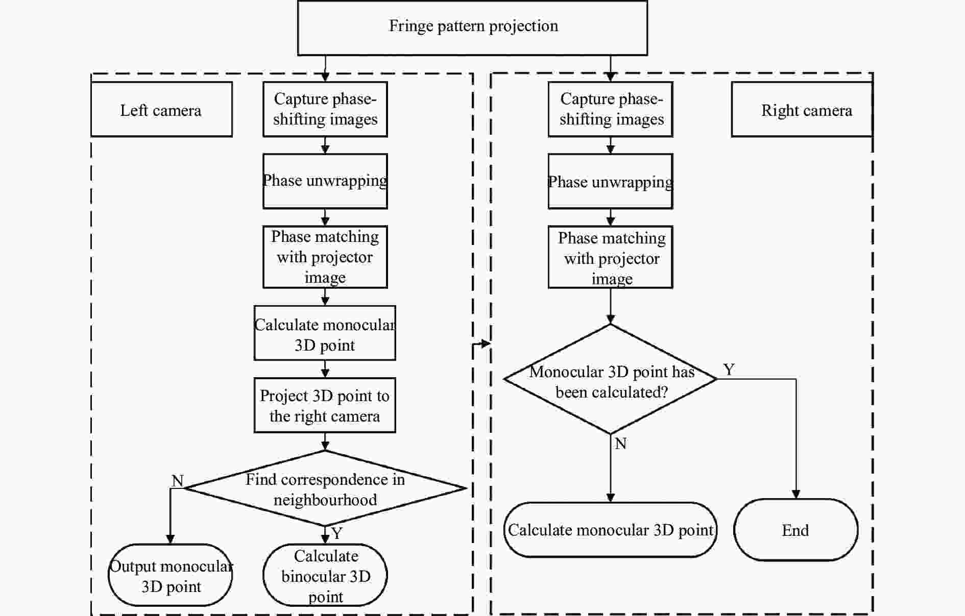
图 2 三重扫描原理流程图
Figure 2. The flowchart of principle of the triple scan
1) 左、右相机同时采集投影仪投射的条纹图像;
2) 由得到的图像恢复和展开相位,结合极线约束确定左相机和投影仪图像的同名点;
3) 根据左相机和投影仪图像的同名点重建三维点;
4) 将三维点反投至右相机图像,结合极线约束搜索投影点的邻域内是否存在与左相机具有相同相位的同名点,若存在,则重建双目三维点;若不存在,则用左相机重建的三维点替代该缺失的双目三维点;
5) 遍历未参与重建双目三维点的右相机图像像素,根据相位与极线约束确定其在投影仪图像中的同名点;
6) 判断该同名点是否已经与左相机重建过三维点,若是,则跳过该重建点;反之,则用右相机和投影仪重建该三维点。
由三重扫描重建三维点云的过程可知,其在双目点云的基础上对于缺失点尽可能地通过单目点进行补充,同时避免了冗余点,保证了重建点云的完整性和准确性。
-
为了说明三重扫描温漂问题并定位原因,文中设计了反光点测量实验,所搭建的双目面结构光系统包含MV-CA050-20GM型号海康工业相机,MVL-KF1228M-12MPE型号海康工业镜头以及DLP4710LC型号投影仪。如图3(a)所示,将双目面结构光视觉传感器固定于光学平台上,并事先在室温为16 ℃时进行标定,然后以空间中5个固定的反光点作为被测对象,见图3(b),在该标定室温和30 ℃的室温下分别对反光点进行三重扫描测量,以双目相机测量得到的反光点圆心坐标为基准,计算温度变化前后单目测量单元和双目相机测量单元所重建的圆心坐标偏差$ \left( {\Delta {x_L},\Delta {y_L},\Delta {z_L}} \right) $、$ \left( {\Delta {x_R},\Delta {y_R},\Delta {z_R}} \right) $,得到表1。
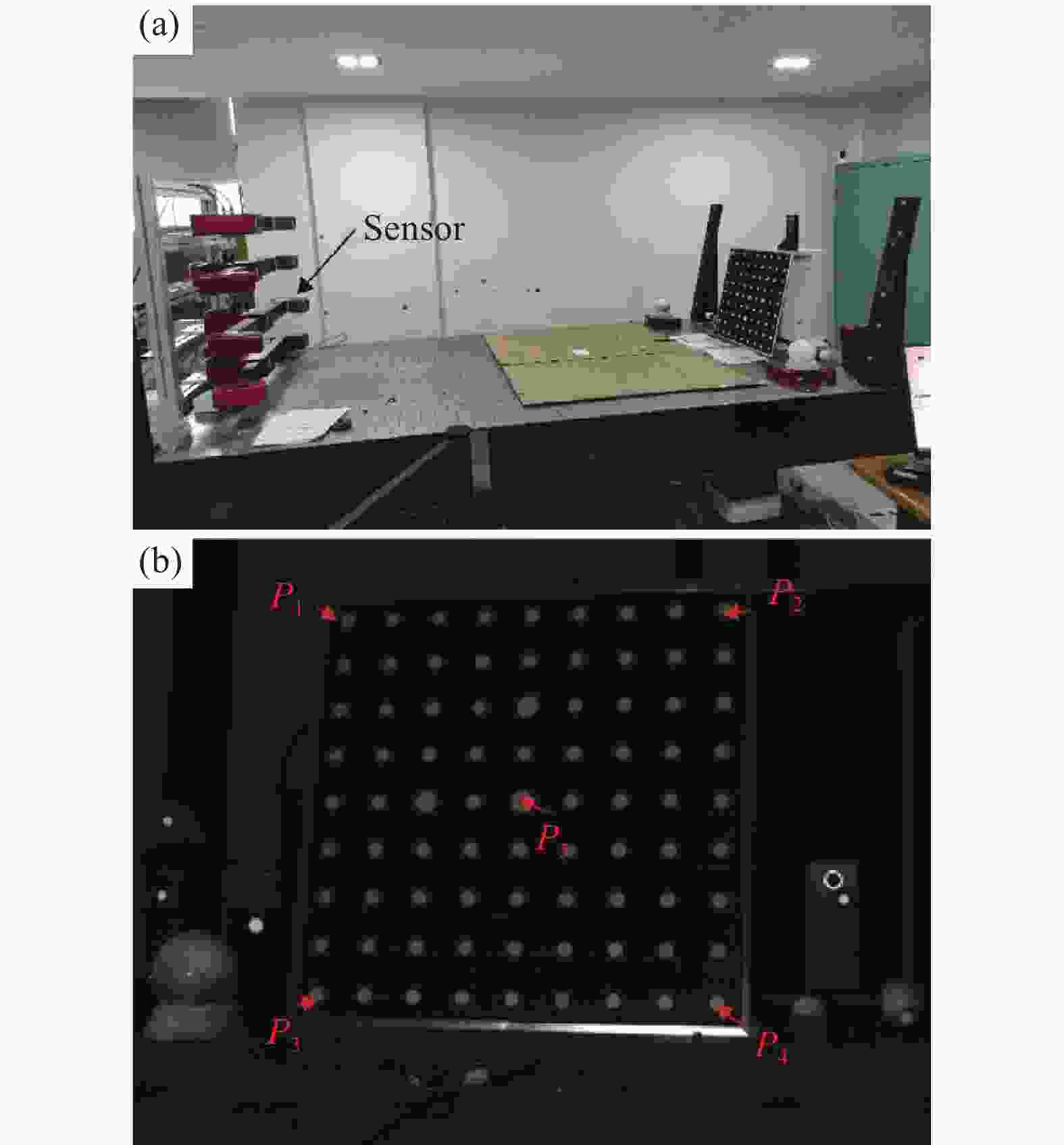
图 3 三重扫描温漂问题复现。 (a) 测试环境;(b) 反光点图像
Figure 3. Triple scan temperature drift problem recurrence. (a) Test environment; (b) The image of the reflection spots
表 1 反光点圆心三维坐标偏差
Table 1. Error of 3D coordinate of the center of the reflection spots
Temperature 16 ℃ 30 ℃ No. $ \Delta {x_L} $/mm $ \Delta {y_L} $/mm $ \Delta {z_L} $/mm $ \Delta {x_R} $/mm $ \Delta {y_R} $/mm $ \Delta {z_R} $/mm $ \Delta {x_L} $/mm $ \Delta {y_L} $/mm $ \Delta {z_L} $/mm $ \Delta {x_R} $/mm $ \Delta {y_R} $/mm $ \Delta {z_R} $/mm 1 0.10 0.07 0.13 0.08 0.06 0.12 1.23 0.56 5.33 1.02 0.50 −4.82 2 0.09 0.04 0.08 0.07 0.04 0.10 0.98 0.54 4.98 1.01 0.53 −4.77 3 0.09 0.05 0.06 0.05 0.05 0.05 1.01 0.59 4.90 0.94 0.56 −4.85 4 0.08 0.06 0.07 0.05 0.06 0.06 1.07 0.58 5.18 0.96 0.46 −5.00 5 0.05 0.10 0.14 0.06 0.07 0.08 1.15 0.74 5.02 0.88 0.53 −4.93 AVG 0.08 0.06 0.10 0.06 0.06 0.08 1.09 0.60 5.08 0.96 0.52 −4.87 由表1数据可知,在温度变化前单目测量单元与双目测量单元所重建的反光点圆心三维坐标各个分量的平均偏差均不超过0.1 mm,而当温度升高时两者存在较大的偏差,且左、右单目重建点分别位于双目重建点的两侧,发生了点云分层现象。考虑到反光点圆心的像素坐标与双目相机相关,而相位值与投影仪相关联,因此为了进一步分析造成点云分层的原因,可将升温前后左、右相机采集的图像中反光点圆心的像素坐标和相位值是否发生变化作为依据,把造成点云分层的相机和投影仪因素解耦,以分别判断双目相机和投影仪的位置是否发生偏移,基于此,得到表2。
表 2 反光点圆心像素坐标和相位值变化量
Table 2. The pixel coordinate and phase variation of the center of the reflection spots
No. $ \Delta {u_l} $/pixel $ \Delta {v_l} $/pixel $ \Delta {u_r} $/pixel $ \Delta {v_r} $/pixel $\Delta P_h$
/10−3 rad1 0.11 0.04 0.08 0.06 1.72 2 0.11 0.11 0.10 0.07 2.46 3 0.16 0.08 0.08 0.09 2.03 4 0.14 0.11 0.13 0.08 2.99 5 0.07 0.00 0.12 0.03 2.86 AVG 0.12 0.07 0.10 0.07 2.41 由表2中数据可知,升温前后左、右相机反光点圆心的像素坐标和相位值发生了变化,可认为双目相机与投影仪由于温度变化产生了位置偏移,且依据表1中的坐标误差数据和相关研究[18]可知位置误差对于$ z $方向上的测量精度影响更大,因此文中将着重分析投影仪和双目相机位置误差对于三重扫描测量系统$ z $方向测量精度的影响。
-
投影仪位置误差对测量精度影响见图4。为简便分析,考虑平面内的位置误差影响且假设双目相机对称放置,相机1、2以及投影仪两两交汇于空间点$ P $。如图4(b)所示,当投影仪由于温度变化使得位置改变,点$ P $的相位值从$ {\varphi _0} $变为$ {\varphi _1} $,此时投影仪的外参未进行更新,等价于投影仪在原来的位置以对应于相位为$ {\varphi _1} $的光束分别与相机1、2成像于点$ {P_1} $、$ {P_2} $。由于双目点$ P $坐标不受投影仪位置误差的影响,因此投影仪位置变化造成了单目点云精度损失。设$ {P_1} $与双目点$ P $在$ x $方向上的误差为$ \Delta {x_1} $,$ {P_2} $与双目点$ P $在$ x $方向上的误差为$ \Delta {x_2} $,那么可以得到$ {P_1} $、$ {P_2} $与$ P $在$ z $方向上的误差$ \Delta {z_{m1}} $、$ \Delta {z_{m2}} $为:

图 4 投影仪位置误差对测量精度影响示意图。 (a) 温漂前三重扫描成像示意图;(b) 温漂后三重扫描成像示意图
Figure 4. Schematic diagram of the influence of projector position error on measurement accuracy. (a) Schematic diagram of triple scan imaging before temperature drift; (b) Schematic diagram of triple scan imaging before temperature drift
$$ \begin{gathered} \Delta {z_{m1}} = \dfrac{{\Delta {x_1}}}{{\tan({\theta }/{2})}} \\ \Delta {z_{m2}} = \dfrac{{\Delta {x_2}}}{{\tan ({\theta }/{2})}} \\ \end{gathered} $$ (7) 式中:$ \theta $为双目相机的视差角。由图中可知$ {P_1} $、$ {P_2} $沿着$ z $方向分别位于双目点的两侧。
由几何关系可知:
$$ \begin{gathered} \frac{{\Delta {x_1}}}{{d + \Delta {z_{m1}}}} = \frac{{\rm{{d}}}x}{f} \\ \frac{{\Delta {x_2}}}{{d - \Delta {z_{m2}}}} = \frac{{{\rm{d}}x}}{f} \\ \end{gathered} $$ (8) 式中:$ d $表示工作距;$ {\rm{d}}x $表示相位$ {\varphi _0} $、$ {\varphi _1} $对应像素的空间实际距离;$ f $为投影仪焦距。结合公式(7)、(8)可得:
$$ \begin{array}{l}\Delta {z}_{m1}=\dfrac{d\cdot {\rm{d}}x}{f\mathrm{tan}({\theta }/{2})-{\rm{d}}x}\\ \Delta {z}_{m2}=\dfrac{d\cdot {\rm{d}}x}{f\mathrm{tan}({\theta }/{2})+{\rm{d}}x}\end{array} $$ (9) -
当双目相机位置由于温度变化引起改变(如图5所示),不仅使得单目点$ {P_1} $、$ {P_2} $位置发生偏移,还使得双目点的位置偏移至$ {P'} $。设$ {P_1} $在相机1中的投影点像素$ u $坐标发生偏移$ \Delta {u_1} $,$ {P_2} $在相机2中的投影点像素$ u $坐标发生偏移$ \Delta {u_2} $那么可以得到$ {P_1} $、$ {P_2} $在$ z $方向上相对于$ P $的误差$ \Delta {z_{b1}} $、$ \Delta {z_{b2}} $:
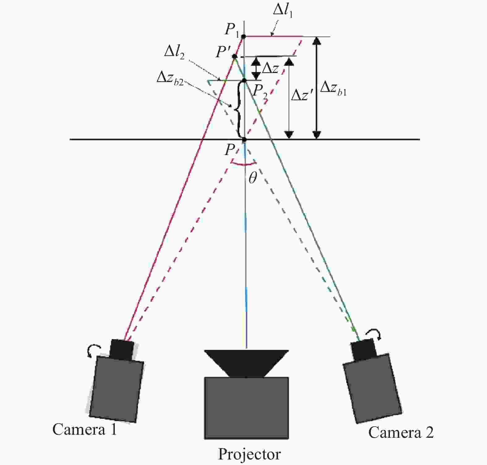
图 5 双目相机位置误差对测量精度影响示意图
Figure 5. Schematic diagram of the influence of binocular camera position error on measurement accuracy
$$ \begin{gathered} \Delta {z_{b1}} = \dfrac{{\Delta {l_1}}}{{\tan ({\theta }/{2})}} = \dfrac{{\lambda \Delta {u_1}}}{{\tan ({\theta }/{2})}} \\ \Delta {z_{b2}} = \dfrac{{\Delta {l_2}}}{{\tan ({\theta }/{2})}} = \dfrac{{\lambda \Delta {u_2}}}{{\tan ({\theta }/{2})}} \\ \end{gathered} $$ (10) 式中:$ \lambda $表示像素当量;$ \Delta {l_1} $、$ \Delta {l_2} $表示投影点像素偏移量所对应的空间实际尺寸。
进一步地,可以得到单目点相对于双目点$ {P'} $的温漂量$ \Delta z $为:
$$ \Delta z\approx \frac{1}{2}\cdot \left(\Delta {z}_{b1}-\Delta {z}_{b2}\right)=\frac{\lambda \left(\Delta {u}_{1}-\Delta {u}_{2}\right)}{2\mathrm{tan}({\theta }/{2})} $$ (11) 另一方面,$ {P'} $相对于温漂前的双目点$ P $在$ z $方向上误差$ \Delta {z'} $为:
$$ \Delta {z}{{'}}\approx \dfrac{1}{2}\cdot \left(\Delta {z}_{b1}+\Delta {z}_{b2}\right)=\dfrac{\lambda \left(\Delta {u}_{1}+\Delta {u}_{2}\right)}{2\mathrm{tan}({\theta }/{2})} $$ (12) 综合以上两种情况可知,对于三重扫描测量系统,投影仪因温度变化引起的位置误差对测量精度的影响表现为单目点云在深度方向上的误差,从而产生其在双目点云两侧分层的现象。而双目相机位置误差不仅会造成单目点云与双目点云分层,还会引起双目点云自身的精度损失。然而,一方面结合表2数据可以得到,反光点圆心相位值平均变化为2.41×10⁻³ rad,而投影仪最终合成的条纹周期为2 040,所以投影仪中一个像素对应的相位值为3.08×10⁻³ rad,相当于投影仪温漂使得反光点圆心在投影仪图像中的像素坐标偏移了0.78 pixel,远大于双目相机温漂引起图像像素坐标变化的影响。据此可知投影仪相较于工业相机,其对于温度变化更加敏感。另一方面,现有许多针对相机的温漂补偿方法[19],能够使得双目相机温漂可控。基于以上两点,双目相机对于三重扫描测量系统精度的影响有限,而投影仪温漂对于测量精度的影响占据主导地位。
-
“左相机-右相机”结构光测量单元仅利用投影仪投射图案作为特征约束并未加入投影仪参数进行重建计算,因此温度漂移造成投影仪参数变化并未对此单元重建结果有影响。为此,本节通过将投影仪投射正交条纹图案映射到投影仪中以实现投影仪参数修正,最后基于双目点与投影仪图像像素一一映射关系来最优估计当前温度下投影仪外参,从而实现对投影仪温漂补偿。
-
对于左相机图像上的一点$ {p_L} $,结合其在右相机图像上的同名点$ {p_R} $可通过双目视觉模型恢复三维点坐标$ {P_B} $。同样的,$ {p_L} $结合在投影仪图像上的同名点$ {p_P} $也可恢复三维点坐标$ {P_M} $。在系统完成标定后,$ {P_B} $和$ {P_M} $对应于空间中的同一点,然而如前文所述,温度变化使得标定结果不再适用于当前的环境,使得$ {P_B} $与$ {P_M} $存在一定的误差,从宏观上来看双目点云与单目点云发生了“分层”现象。为了获取双目重建三维点$ {P_B} $在投影仪的像素坐标,需要投影仪投射正交条纹并通过左相机采集条纹图像,再根据1.1.1节所阐述的相位恢复与展开的方法获取左相机图像每个像素具有的唯一绝对相位坐标$ \left( {{\varphi _u},{\varphi _v}} \right) $。而对于投影仪,其绝对相位图为未受物体调制的标准相位,通过三频四相得到的合成相位周期为:
$$ T = \frac{{{T_1}{T_2}{T_3}}}{{{T_1}{T_2} + {T_2}{T_3} - 2{T_1}{T_3}}} $$ (13) 则投影仪每个像素点所占的相位跨度为:
$$ \Delta \varphi = 2\pi \frac{{{T_1}{T_2} + {T_2}{T_3} - 2{T_1}{T_3}}}{{{T_1}{T_2}{T_3}}} $$ (14) 显然,$ {p_L} $在投影仪图像上的同名点$ {p_P} $具有相同的绝对相位坐标,因此可以通过左相机图像的绝对相位坐标求解同名点$ {p_P} $在投影仪图像上的像素坐标$ \left( {{u_P},{v_P}} \right) $:
$$ \left\{ \begin{gathered} {u_P} = \frac{{{\varphi _u}}}{{\Delta \varphi }} \\ {v_P} = \frac{{{\varphi _v}}}{{\Delta \varphi }} \\ \end{gathered} \right. $$ (15) 双目点$ {P_B} $在左相机图像上的投影点为$ {p_L} $,借助左相机图像与投影仪图像的同名点匹配关系$ \left\{ {{p_L},{p_P}} \right\} $,而可以得到点$ {P_B} $在投影仪上的投影点坐标为$ {p_P} = \left( {{u_P},{v_P}} \right) $,如图6所示。

图 6 正交条纹建立双目点在投影仪图像中的像素映射关系
Figure 6. Establishing the pixel mapping relationship of binocular points in the projector image through the orthogonal fringe projection
-
通过投影仪投射正交条纹,可以建立双目重建点与其在投影仪图像中的像素映射关系,得到双目点在投影仪中的像素坐标,进一步根据该映射关系作为约束,优化求解投影仪的外参矩阵使得公共区域的双目点在投影仪上的重投影误差最小:
$$ T_P^* = \arg \min {\sum\limits_{i = 1}^n {\left\| {p_P^i - \frac{1}{{s_P^i}}{K_P}{T_P}P_B^i} \right\|} ^2} $$ (16) 式中:$ n $为公共点的数量;$ p_P^i $、$ P_B^i $为公共点在投影仪上的像素齐次坐标以及在世界坐标系下的齐次坐标;$ s_P^i $为尺度因子;$ {K_P} $为投影仪的内参矩阵;$ {T_P} $定义为未知的投影仪外参矩阵,含有12个未知量。$ {T_P} $可表示为:
$$ {T_P} = \left[ {\begin{array}{*{20}{c}} R&t \\ {{0^{\rm{T}}}}&1 \end{array}} \right] $$ (17) 旋转矩阵$ R $需满足正交性,即:
$$ {R^{\rm{T}}}R = I $$ (18) 式中:$ I $定义为单位矩阵。因此,通过最小化下面的目标函数:
$$ E = {\sum\limits_{i = 1}^n {\left\| {p_P^i - \frac{1}{{s_P^i}}{K_P}{T_P}P_B^i} \right\|} ^2} + C\left\| {{R^{\rm{T}}}R - I} \right\|_F^2 $$ (19) 式中:$ C $为惩罚因子;$ {\left\| \cdot \right\|_F} $定义为矩阵的F范数。该最优化问题可以首先通过直接线性变换法(DLT)计算得到初值,再通过列文伯格-马夸尔特算法求解在该温度下的投影仪外参。
-
为了验证文中算法的有效性,使用第2节所搭建的双目面结构光系统分别在实验室环境和工业现场下距离被测物2.5 m的位置进行数据采集。
-
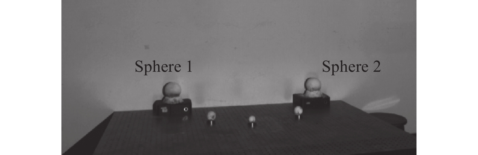
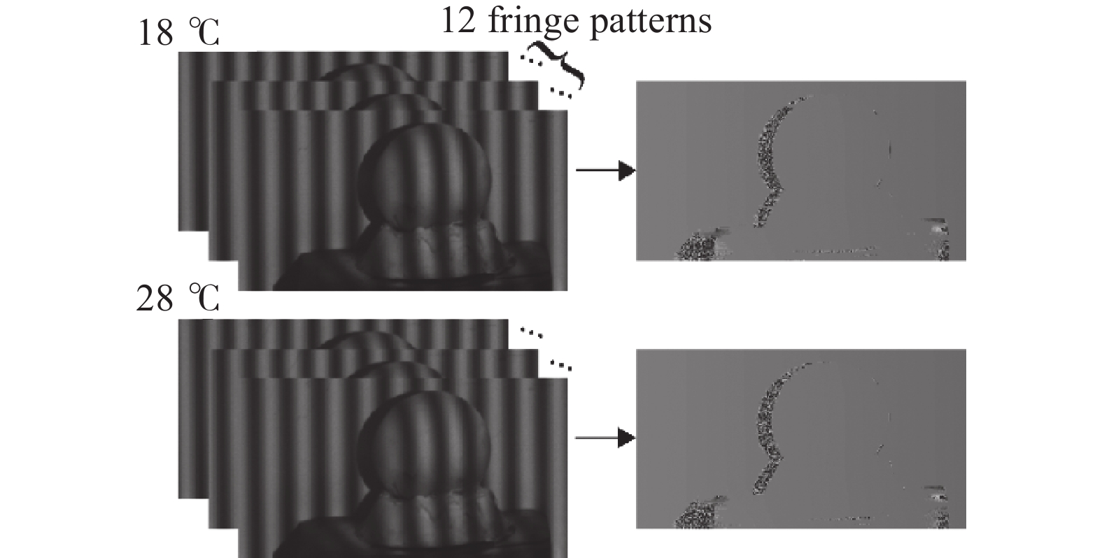
被测对象为金属球,如图7所示。首先在室温为18 ℃的环境下对双目结构光系统进行标定并立即采集金属球的条纹图案,然后将室温升高至28 ℃,再次采集条纹图像,其中升温前后左相机对球1条纹测量结果如图8所示。以左相机的相机坐标系作为世界坐标系,分别基于左相机-投影仪、右相机-投影仪、左相机-投影仪-右相机重建三维点云,然后裁剪得到球面点云,通过构建以下最小二乘问题拟合球面方程,计算球心坐标$ \left( {a,b,c} \right) $:
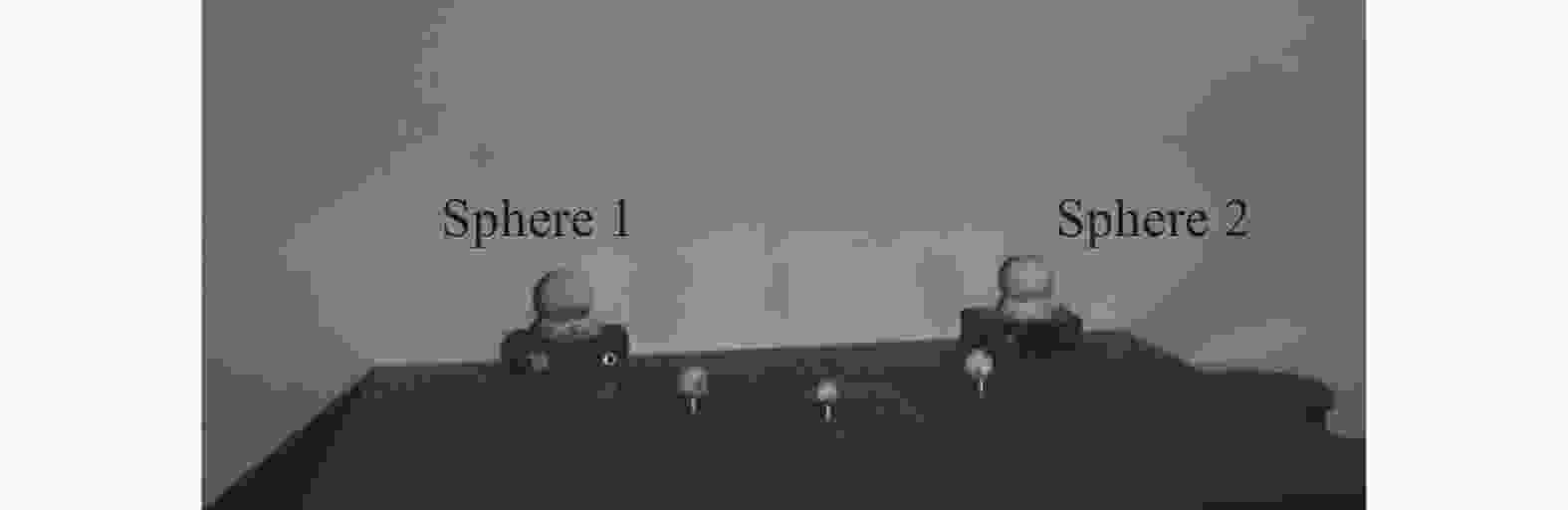
图 7 金属球图像
Figure 7. Metal sphere

图 8 条纹测量结果
Figure 8. The result of fringe pattern measurement
$$ F = \min \sum\limits_{i = 1}^n {{{\left[ {{{\left( {{x_i} - a} \right)}^2} + {{\left( {{y_i} - b} \right)}^2} + {{\left( {{z_i} - c} \right)}^2} - {R^2}} \right]}^2}} $$ (20) 式中:$ \left( {{x_i},{y_i},{z_i}} \right) $为球面点云的三维坐标;$ R $为球半径。
以双目点云为基准,通过计算同一温度下左、右相机单目点云中的球心与双目点云球心的距离,对点云分层的程度进行定量评价:
$$ \begin{gathered} {d_L} = \left\| {{P_{LS}} - {P_{BS}}} \right\| \\ {d_R} = \left\| {{P_{RS}} - {P_{BS}}} \right\| \\ \end{gathered} $$ (21) 式中:$ {d_L} $、$ {d_R} $分别表示左、右单目点云球心与双目点云球心的距离;$ {P_{LS}} $、$ {P_{RS}} $分别为左、右单目点云球心三维坐标;$ {P_{BS}} $为双目点云球心三维坐标。根据上述计算方式评价升温前后球面点云的分层情况,其结果如表3所示。
表 3 不同温度下单目测量单元与双目测量单元重建球的球心距离
Table 3. Sphere center distance between monocular measurement unit and binocular measurement unit at different temperature
No. 18 ℃ 28 ℃ Left camera Right camera Left camera Right camera Sphere1
/mmSphere2
/mmSphere1
/mmSphere2
/mmSphere1
/mmSphere2
/mmSphere1
/mmSphere2
/mm1 0.26 0.20 0.24 0.24 1.77 1.45 1.68 1.60 2 0.26 0.31 0.20 0.22 1.79 1.44 1.74 1.56 3 0.22 0.26 0.24 0.17 1.90 1.45 1.72 1.78 4 0.24 0.18 0.27 0.20 1.97 1.61 1.85 1.61 5 0.17 0.18 0.24 0.31 2.01 1.47 1.63 1.81 AVG 0.23 0.23 0.24 0.23 1.89 1.48 1.73 1.67 由表3中数据可知,在室温为18℃时,由于传感器标定温度和工作温度接近,投影仪温漂较小,此时左、右单目点云的球心与双目点云中的球心距离相差不大,其中球1的平均球心距为0.23 mm和0.24 mm,球2的平均球心距为0.23 mm和0.23 mm,单目点云与双目点云未产生明显的分层现象。当环境温度上升到28 ℃时,点云重建结果如图9(a)所示。此时投影仪发生温度漂移,由于标定参数与真实的标定参数不一致,导致左、右单目中球1平均球心距分别增大到1.89 mm和1.73 mm,球2的平均球心距增大到1.48 mm和1.67 mm,发生了明显的分层现象。在该温度下投射和采集正交条纹图像,根据文中的方法对投影仪的外参进行修正,并重新进行点云的重建,见图9(b),得到修正后的球心距离误差,结果如表4所示。

图 9 28 ℃金属球点云。 (a) 双目点云与传感器发生温漂后重建的单目点云;(b) 双目点云与传感器温漂补偿后重建的单目点云
Figure 9. Point cloud of metal sphere at 28 ℃. (a) Binocular point cloud and monocular point cloud reconstructed by the sensor which has temperature drift; (b) Binocular point cloud and monocular point cloud reconstructed by the sensor after temperature drift compensation
表 4 修正后球心距离
Table 4. Sphere center distance error after correction
Left camera Right camera No. Sphere1
/mmSphere2
/mmSphere1
/mmSphere2
/mm1 0.36 0.32 0.36 0.33 2 0.37 0.38 0.36 0.38 3 0.33 0.43 0.41 0.44 4 0.36 0.29 0.34 0.30 5 0.36 0.42 0.35 0.42 AVG 0.36 0.37 0.36 0.37 由表中数据可知,修正后左、右单目点云中球1平均球心距为0.36 mm和0.36 mm,球2的球心距为0.37 mm和0.37 mm,相较于未修正前减小了1.53 mm、1.37 mm、1.11 mm以及1.30 mm,球心距平均减小了78.2%,实验数据表明,文中方法能够在双目结构光传感器的三重扫描应用中使得单目点云与双目点云不再产生明显的分层现象,证明了文中方法的有效性。
-
为了证明文中方法的实用性,根据在汽车制造现场实际发生温漂的传感器图像重建点云,采用文中的方法进行修正。以某汽车厂的门槛零件作为被测对象,见图10。

图 10 汽车门槛底座零件图
Figure 10. Photograph of car threshold base parts
通过采集被测零件的条纹图进行三维重建得到单目点云与双目点云,如图11(a)所示。投影仪由于温度漂移,使重建得到的单目点云与双目点云产生了严重的分层现象,导致通过三重扫描融合得到的点云重建结果不可靠。以双目点云为基准,计算相机图像同一像素对应的单目点和双目点的欧式距离作为定量评价标准,其结果如图12(a)、(c)所示。此时同一像素对应的双目点和单目点的平均距离分别为13.19 mm和12.96 mm。

图 11 汽车门槛零件点云重建。 (a) 双目点云与单目点云;(b) 点云局部剖面图
Figure 11. Car threshold base parts point cloud reconstruction. (a) Monocular point cloud and binocular point cloud; (b) Partial profile view of the point clouds
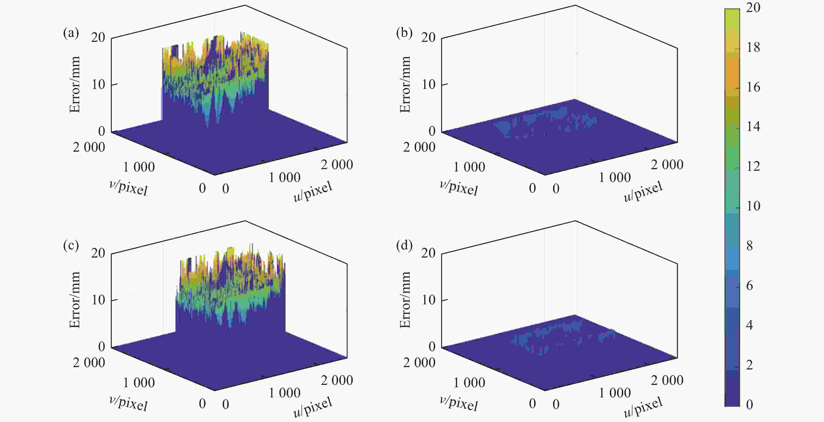
图 12 单目点云与双目点云距离误差。 (a) 发生温漂后左相机重建的单目点与双目点的空间距离误差;(b) 温漂补偿后左相机重建的单目点与双目点的空间距离误差;(c) 发生温漂后右相机重建的单目点与双目点的空间距离误差;(d) 温漂补偿后右相机重建的单目点与双目点的空间距离误差
Figure 12. The error between monocular point cloud and binocular point cloud. (a) The error between monocular points reconstructed by the left camera and binocular points after temperature drift; (b) The error between monocular points reconstructed by the left camera and binocular points after temperature drift compensation; (c) The error between monocular points reconstructed by the right camera and binocular points after temperature drift; (d) The error between monocular points reconstructed by the right camera and binocular points after temperature drift compensation
通过正交条纹投影图像数据对投影仪的外参进行修正,作为新的标定参数进行三重扫描点云重建的入参,分别得到双目点云和单目点云,见图11(b)。同样以双目点云为基准,其公共区域的点云距离误差见图12(b)、(d)。由此可以看到,该方法显著消除了单目点云与双目点云的分层现象。外参修正后重建得到的单目与双目点云平均距离下降为0.75 mm和0.75 mm,点云距离平均减小94.3%。可以证明文中方法对三重扫描的点云分层现象有明显的改善。
-
文中针对双目面结构光三重扫描测量系统中投影仪温漂问题所导致的点云分层现象,提出了一种基于正交条纹投影的三重扫描温漂在线补偿方法,以在不依靠标定板等先验信息及繁琐标定流程下实现一种快速在线实时温度变化条件下的投影仪参数修正。文中通过正交条纹投影图像建立双目点与投影仪图像坐标间的映射关系,确定双目重建三维点在投影仪中的图像坐标,进而通过最小化重投影误差优化求解得到修正后的投影仪外参,以此为投影仪系统参数完成三重扫描点云重建计算。最后,在实验室环境和工业现场环境下对文中方法的有效性进行验证,结果表明:该方法能够有效改善三重扫描点云分层的问题,使双目点云与单目点云的温漂量减少78.2%和94.3%,为双目结构光传感器的三重扫描在复杂工况稳定性应用提供技术保障。
Temperature drift compensation method for triple scan measuring system of binocular surface structured light
-
摘要: 双目面结构光三重扫描是在条纹投影双目视觉重建的基础上,追加左、右相机与投影仪构成的单目视觉系统重建点云,在反光和凹凸起伏等表面测量应用上具有更好的点云完整性优势。但由于环境温度变化影响,投影仪产生较大温度漂移,导致双目重建点云与单目重建点云发生“分层”现象。为此,文中提出了一种基于正交条纹投影的三重扫描系统温漂在线补偿方法,通过投影仪投射正交条纹来构建双目重建点在投影仪图像中准确的映射关系,并基于双目重建点在投影仪图像中的重投影误差最小化目标函数来求解温漂补偿后的投影仪最优外参数。最后,以金属球和汽车零件作为被测对象进行实验验证,在不依靠标定板等先验信息及繁琐标定流程基础上,所提在线快速补偿方法可以使得双目点云与单目点云温漂量分别减小78.2%和94.3%,极大减轻了温度变化对于三重扫描点云数据拼接影响。Abstract:
Objective The triple scan of the binocular structured light sensors is based on the binocular vision reconstruction of fringe projection, with additional point cloud reconstructed from the monocular vision system consisting of the left or right camera and the projector. Therefore, it has the advantage of better point cloud integrity in the measurement applications of reflective and uneven objects. However, because of the change of ambient temperature which exerts temperature drift impact on the projector, the binocular reconstruction point cloud and monocular reconstruction point cloud are stratified, resulting in the wrong point cloud reconstruction results of the triple scan. To solve this, a temperature drift online compensation method based on the orthogonal fringe projection is provided for the triple scan system of binocular surface structured light. Methods A temperature drift compensation method based on the orthogonal fringe projection and binocular points constraint is provided in this paper. By projecting the orthogonal fringe patterns, the pixel coordinate in the projector image of points which are in the binocular and monocular imaging area can be determined simultaneously. Therefore, the accurate mapping relationship of binocular points in the image of the projector is established (Fig.3). Then based on the objective function of minimizing the reprojection error of the binocular reconstruction point in the projector image, the optimal external parameters of the projector after temperature drift compensation are solved to compensate temperature drift of the projector. Results and Discussions In order to demonstrate the effectiveness and practicability of the proposed method, metal spheres and car threshold base parts were tested. In metal spheres experiments, the spherical center distance between binocular point cloud and monocular point cloud at different temperature is used to quantitatively evaluate the temperature drift level (Tab.1-2). When the temperature drift of the sensor occurs at 28 ℃, the values of spherical center distance on average are 1.89 mm, 1.48 mm, 1.73 mm, 1.67 mm and drop to 0.36 mm, 0.37 mm, 0.36 mm, 0.37 mm after the method is proposed. In car threshold base parts experiments, the Euclidean distance between binocular points and monocular points corresponding to the same pixel is shown (Fig.8). Both results show that temperature drift is decreased after the method is proposed with the temperature drift value reduced by 78.2% and 94.3% on average. Conclusions Focusing on the issue that binocular and monocular point clouds are stratified in the application of the triple scan due to the change of the ambient temperature, the temperature drift online compensation method for triple scan measuring system of binocular surface structured light is proposed. Orthogonal fringe patterns are projected and meanwhile are captured by the binocular cameras. The accurate pixel coordinate in projector image coordinate system of binocular points are acquired by calculating the phase coordinate of every pixel in the camera image and projector image. According to the the constraint of the mapping relationship between binocular points and projector pixels, the external parameters of projector are calculated via minimizing the reprojection error of the binocular points in the projector image to compensate the temperature drift of the projector. The experimental results show that the proposed method can significantly decrease the temperature drift with the value reduced by 78.2% and 94.3% on average, which verifies the effectiveness of the method. This method can provides guarantee for the stability of triple scan and make the application of triple scan a reality. -
Key words:
- triple scan /
- projector /
- orthogonal fringe /
- temperature drift compensation
-
图 3 三重扫描温漂问题复现。 (a) 测试环境;(b) 反光点图像
Figure 3. Triple scan temperature drift problem recurrence. (a) Test environment; (b) The image of the reflection spots
图 4 投影仪位置误差对测量精度影响示意图。 (a) 温漂前三重扫描成像示意图;(b) 温漂后三重扫描成像示意图
Figure 4. Schematic diagram of the influence of projector position error on measurement accuracy. (a) Schematic diagram of triple scan imaging before temperature drift; (b) Schematic diagram of triple scan imaging before temperature drift
图 5 双目相机位置误差对测量精度影响示意图
Figure 5. Schematic diagram of the influence of binocular camera position error on measurement accuracy
图 6 正交条纹建立双目点在投影仪图像中的像素映射关系
Figure 6. Establishing the pixel mapping relationship of binocular points in the projector image through the orthogonal fringe projection
图 9 28 ℃金属球点云。 (a) 双目点云与传感器发生温漂后重建的单目点云;(b) 双目点云与传感器温漂补偿后重建的单目点云
Figure 9. Point cloud of metal sphere at 28 ℃. (a) Binocular point cloud and monocular point cloud reconstructed by the sensor which has temperature drift; (b) Binocular point cloud and monocular point cloud reconstructed by the sensor after temperature drift compensation
图 11 汽车门槛零件点云重建。 (a) 双目点云与单目点云;(b) 点云局部剖面图
Figure 11. Car threshold base parts point cloud reconstruction. (a) Monocular point cloud and binocular point cloud; (b) Partial profile view of the point clouds
图 12 单目点云与双目点云距离误差。 (a) 发生温漂后左相机重建的单目点与双目点的空间距离误差;(b) 温漂补偿后左相机重建的单目点与双目点的空间距离误差;(c) 发生温漂后右相机重建的单目点与双目点的空间距离误差;(d) 温漂补偿后右相机重建的单目点与双目点的空间距离误差
Figure 12. The error between monocular point cloud and binocular point cloud. (a) The error between monocular points reconstructed by the left camera and binocular points after temperature drift; (b) The error between monocular points reconstructed by the left camera and binocular points after temperature drift compensation; (c) The error between monocular points reconstructed by the right camera and binocular points after temperature drift; (d) The error between monocular points reconstructed by the right camera and binocular points after temperature drift compensation
表 1 反光点圆心三维坐标偏差
Table 1. Error of 3D coordinate of the center of the reflection spots
Temperature 16 ℃ 30 ℃ No. $ \Delta {x_L} $/mm $ \Delta {y_L} $/mm $ \Delta {z_L} $/mm $ \Delta {x_R} $/mm $ \Delta {y_R} $/mm $ \Delta {z_R} $/mm $ \Delta {x_L} $/mm $ \Delta {y_L} $/mm $ \Delta {z_L} $/mm $ \Delta {x_R} $/mm $ \Delta {y_R} $/mm $ \Delta {z_R} $/mm 1 0.10 0.07 0.13 0.08 0.06 0.12 1.23 0.56 5.33 1.02 0.50 −4.82 2 0.09 0.04 0.08 0.07 0.04 0.10 0.98 0.54 4.98 1.01 0.53 −4.77 3 0.09 0.05 0.06 0.05 0.05 0.05 1.01 0.59 4.90 0.94 0.56 −4.85 4 0.08 0.06 0.07 0.05 0.06 0.06 1.07 0.58 5.18 0.96 0.46 −5.00 5 0.05 0.10 0.14 0.06 0.07 0.08 1.15 0.74 5.02 0.88 0.53 −4.93 AVG 0.08 0.06 0.10 0.06 0.06 0.08 1.09 0.60 5.08 0.96 0.52 −4.87  下载: 导出CSV
表 2 反光点圆心像素坐标和相位值变化量
Table 2. The pixel coordinate and phase variation of the center of the reflection spots
No. $ \Delta {u_l} $/pixel $ \Delta {v_l} $/pixel $ \Delta {u_r} $/pixel $ \Delta {v_r} $/pixel $\Delta P_h$
/10−3 rad1 0.11 0.04 0.08 0.06 1.72 2 0.11 0.11 0.10 0.07 2.46 3 0.16 0.08 0.08 0.09 2.03 4 0.14 0.11 0.13 0.08 2.99 5 0.07 0.00 0.12 0.03 2.86 AVG 0.12 0.07 0.10 0.07 2.41
下载: 导出CSV
表 3 不同温度下单目测量单元与双目测量单元重建球的球心距离
Table 3. Sphere center distance between monocular measurement unit and binocular measurement unit at different temperature
No. 18 ℃ 28 ℃ Left camera Right camera Left camera Right camera Sphere1
/mmSphere2
/mmSphere1
/mmSphere2
/mmSphere1
/mmSphere2
/mmSphere1
/mmSphere2
/mm1 0.26 0.20 0.24 0.24 1.77 1.45 1.68 1.60 2 0.26 0.31 0.20 0.22 1.79 1.44 1.74 1.56 3 0.22 0.26 0.24 0.17 1.90 1.45 1.72 1.78 4 0.24 0.18 0.27 0.20 1.97 1.61 1.85 1.61 5 0.17 0.18 0.24 0.31 2.01 1.47 1.63 1.81 AVG 0.23 0.23 0.24 0.23 1.89 1.48 1.73 1.67
下载: 导出CSV
表 4 修正后球心距离
Table 4. Sphere center distance error after correction
Left camera Right camera No. Sphere1
/mmSphere2
/mmSphere1
/mmSphere2
/mm1 0.36 0.32 0.36 0.33 2 0.37 0.38 0.36 0.38 3 0.33 0.43 0.41 0.44 4 0.36 0.29 0.34 0.30 5 0.36 0.42 0.35 0.42 AVG 0.36 0.37 0.36 0.37
下载: 导出CSV
-
[1] 左超, 张晓磊, 胡岩, 等. 3 D真的来了吗?——三维结构光传感器漫谈[J]. 红外与激光工程, 2020, 49(03): 9-53. Zuo Chao, Zhang Xiaolei, Hu Yan, et al. Has 3D finally come of age?—An introduction to 3D structured-light sensor [J]. Infrared and Laser Engineering, 2020, 49(3): 0303001. (in Chinese) [2] 王素琴, 陈太钦, 张峰, 等. 面向复杂机械零件形貌测量的高精度三维重建方法[J]. 红外与激光工程, 2022, 51(07): 330-340. Wang Suqin, Chen Taiqin, Zhang Feng, et al. High-precision 3D reconstruction method for topography measurement of complex mechanical parts [J]. Infrared and Laser Engineering, 2022, 51(7): 20210730. (in Chinese) [3] Xu J, Zhang S. Status, challenges, and future perspectives of fringe projection profilometry [J]. Optics and Lasers in Engineering, 2020, 135: 106193. doi: 10.1016/j.optlaseng.2020.106193 [4] Zuo C, Feng S J, Huang L, et al. Phase shifting algorithms for fringe projection profilometry: A review [J]. Optics and Lasers in Engineering, 2018, 109: 23-59. doi: 10.1016/j.optlaseng.2018.04.019 [5] 殷永凯, 张宗华, 刘晓利, 等. 条纹投影轮廓术系统模型与标定综述[J]. 红外与激光工程, 2020, 49(03): 127-144. doi: 10.3788/IRLA202049.0303008 Yin Yongkai, Zhang Zonghua, Liu Xiaoli, et al. Review of the system model and calibration for fringe projection profilometry [J]. Infrared and Laser Engineering, 2020, 49(3): 0303008. (in Chinese) doi: 10.3788/IRLA202049.0303008 [6] Robert Heiland. Triangulation in metrology: Proven Principle with a Future [EB/OL]. (1999-01-26) [2023-07-18]. https://www.gom.com. [7] Hsu C W, Rao G, He C Y, et al. Thermal error analysis and compensation in structured light system by virtual-point-based method[C]//2021 IEEE 11th Annual International Conference on CYBER Technology in Automation, Control, and Intelligent Systems (CYBER), 2021: 373-378. [8] Adamczyk M. Temperature compensation method for raster projectors used in 3D structured light scanners [J]. Sensors, 2020, 20(20): 5778. [9] Hu P Y, Yang S M, Zhang G F, et al. High-speed and accurate 3D shape measurement using DIC-assisted phase matching and triple-scanning [J]. Optics and Lasers in Engineering, 2021, 147: 106725. doi: 10.1016/j.optlaseng.2021.106725 [10] Rao G, Song L B, Zhang S, et al. Depth-driven variable-frequency sinusoidal fringe pattern for accuracy improvement in fringe projection profilometry [J]. Optics Express, 2018, 26(16): 19986-20008. doi: 10.1364/OE.26.019986 [11] Zheng D L, Da F P, Qian K M, et al. Phase-shifting profilometry combined with Gray-code patterns projection: unwrapping error removal by an adaptive median filter [J]. Optics Express, 2017, 25: 4700-4713. doi: 10.1364/OE.25.004700 [12] Xing S, Guo H W. Temporal phase unwrapping for fringe projection profilometry aided by recursion of chebyshev polynomials [J]. Applied Optics, 2017, 56: 1591-1602. doi: 10.1364/AO.56.001591 [13] 郭创为, 王阳, 邹文哲, 等. 基于多频外差原理的相位校正方法研究[J]. 红外与激光工程. 2023, 52(05): 304-311. Guo Chuangwei, Wang Yang, Zou Wenzhe, et al. Study of phase correction method based on multi-frequency heterodyne principle [J]. Infrared and Laser Engineering, 2023, 52(5): 20220697. (in Chinese) [14] Zhang S, Yau S T. Generic nonsinusoidal phase error correction for three-dimensional shape measurement using a digital video projector [J]. Applied Optics, 2007, 46: 36-43. [15] 马颂德, 张正友. 计算机视觉——计算理论与算法基础[M]. 北京: 科学出版社, 1998. [16] Feng S J, Zuo C, Zhang L, et al. Calibration of fringe projection profilometry: A comparative review [J]. Optics and Lasers in Engineering, 2021, 143: 106622. doi: 10.1016/j.optlaseng.2021.106622 [17] Zhang S, Huang P S. Novel method for structured light system calibration [J]. Optical Engineering, 2006, 45(8): 083601. doi: 10.1117/1.2336196 [18] 刘胜道, 邢成聪, 周国华. 远距离三维坐标测量中双目视觉系统的测量精度分析[J]. 激光与光电子学进展, 2021, 58(14): 439-445. Liu Shengdao, Xing Chengcong, Zhou Guohua. Measuring precision analysis of binocular vision system in remote three-dimensional coordinate measurement [J]. Laser & Optoelectronics Progress, 2021, 58(14): 1415007. (in Chinese) [19] Adamczyk M, Liberadzki P, Sitnik R. Temperature compensation method for digital cameras in 2D and 3D measurement applications [J]. Sensors, 2018, 18(11): 3685. doi: 10.3390/s18113685 -

 点击查看大图

计量
- 文章访问数: 96
- HTML全文浏览量: 23
- PDF下载量: 30
- 被引次数: 0

