


-
随着科学技术的发展,复杂曲面在航空航天、光学工程、船舶等领域的应用日益广泛[1]。复杂曲面零件的表面粗糙度直接影响其服役的性能、效率和寿命。因此,提高复杂曲面零件表面质量,对于提高其服役性能具有重要影响,特别是光学元件。各种光学元件被广泛应用于不同种类的光电系统中,巨大的高精度加工需求对相关光学元件的加工面形精度和面型复杂程度也提出了更高的要求。
针对光学元件的加工,李世杰等[2]采用单点金刚石车削加工的方式获得了较高质量的硫化锌平面元件,但其加工方式对光学元件的复杂面形具有局限性。与传统加工方式相比,工业机器人辅助加工方式成本低,自由度高,加工口径范围广,具有灵活性好、通用性强、易于拓展等优点[3-4]。目前机器人辅助加工在磨削、铣削、抛光、喷涂等领域应用广泛,杨锐等[5]结合机器人控制和轮式抛光技术的优点,提出了基于工业机器人的轮式抛光技术,对平面玻璃进行了加工。周俊锋等[6]采用铣削机器人对汽车铝合金零部件进行加工,验证了采用铣削机器人工艺加工方法相比传统数控机床加工成本下降了20%,加工效率提升了60%。Yang[7]、唐洋洋等[8]均开展了针对复杂曲面的机器人磨削加工的研究,证明了机器人磨削加工方法的实用性和有效性。工业机器人辅助加工的重点在于末端执行器的设计,为了更好地应对光学元件的难加工问题,如加工深腔、高陡度光学元件等复杂元件,需要设计合理的悬臂结构以避免加工干涉[9]。在此,提出一种公-自转轮带磨削方法,前期研究结果表明,其可以有效去除前置工序在工件表面造成的纹理,提高工件表面质量,并且公-自转的运动方式能够避免由单旋转运动带来的去除函数非高斯分布问题[10]。但在加工中发现,因悬臂结构质量较大,而机器人辅助加工作为一种接触加工方式,其末端执行器输出压力稳定与否会直接影响工件的面形精度,因此如何对悬臂结构进行重力补偿,从而实现恒力控制尤为关键。
机器人辅助加工中末端执行器的力控制通常应用于磨削、抛光、去毛刺等精细化加工过程中,机器人通过搭载力传感器,将传感器的检测信息作为力反馈信号,实现机器人对输出压力的实时控制,使机器人能够稳定准确地完成作业。随着工业生产的自动化发展,集成式、一体化的力控装置成为机器人力控制的研究重点。目前国内外学者关于机器人末端执行器的恒力控制主要集中于机械式、电驱式、气动式等方式[11]。机械式末端执行器通常采用柔顺辅助装置,例如线性弹簧、阻尼等进行力控制。Ahn J H等[12]设计了一种基于弹簧补偿的机械柔顺控制装置,用于优化模具的抛光,该装置虽能对输出压力起到一定的柔顺调节作用,但其力控精度低且属于开环控制,无法实现输出压力的主动调节。Yang等[7]将柔性弹簧嵌入滚珠丝杠系统中,研制了机器人磨削系统中的刚柔耦合力控末端执行器,使力控偏差降低了60%,实现了偏差范围2 N的控制精度。电驱式末端执行器以电机控制为主,通过电流控制策略对输出压力进行调节。陈祥[13]设计了一种球形公自转抛光工具用于加工光学曲面,采用音圈电机作为末端力的加载方式,在0~60 N内,装置与工件之间的接触力相对误差小于10%。常浩等[14]利用音圈电机能够产生较长行程恒定电磁力的特点,搭建微小电磁力恒力特性实验系统,获得了电磁力误差小于等于5%的稳定输出。Abd El Khalick Mohammad等[15-16]设计了一种电驱式末端执行器力控装置,通过线性空心音圈电机进行伸缩,实现柔顺控制,降低了主轴惯性效应带来的影响,但其结构和控制过程都相对复杂,成本较高,长时间运行时电机发热影响力控精度。而气动式末端执行器多采用气动系统进行压力控制,可以独立于机器人本体进行力控,具有无污染、维护便捷、输出力大等优点,并且在输出压力稳定的同时成本较低。气动式末端执行器因其简单的控制方式与良好的柔顺性能被广泛应用于机器人末端执行器力控系统。唐洋洋等[8]设计了一种机器人柔性砂带磨削力控制系统,能够实现钛合金和航空发动机叶片磨削加工过程的恒力加载,但是其控制偏差为±4 N,控制精度较低。马文超[17]针对风力发电叶片的机器人恒力打磨问题,设计了一种基于气缸控制输出的恒力控制装置,装置在倾角和位移因素影响下,输出力误差可以控制在±6 N范围内,调节时间可以控制在500 ms以内,输出力波动范围小于20%。Jin M等[18]设计了一种基于气囊加工的恒力控制系统,实现了打磨过程中的接触力稳态误差在±2 N以内。
基于此,文中提出了一种机器人辅助轮带磨削方法,并设计轮带磨削装置的重力补偿系统;然后,基于Hertz接触理论和Preston方程,建立了轮带磨削装置的去除函数。最后,对碳化硅曲面和硫化锌非球面进行了磨削验证实验。
-
如图1所示,轮带磨削装置为一种可控压力的公-自转轮带磨削机械臂末端执行器,由轮带磨削组件、电机驱动组件、气动旋转组件以及支撑组件组成。该装置采用电机驱动,由一对正交放置的锥齿轮控制产生两个正交方向的旋转运动,即公转运动和接触轮自转运动。当接触轮带与工件表面接触时,它主要通过接触轮自转进行材料去除。公转运动可以将接触轮在工件上的轨迹复杂化,消除磨纹,从而使最终的材料去除为伪高斯分布。

图 1 轮带磨削装置及原理示意图。(a) 悬臂组件;(b) 公-自转轮带磨削装置;(c) 装置工作原理
Figure 1. Schematic diagram of wheel belt grinding device and principle. (a) Cantilever component; (b) Rotation-revolution abrasive belt grinding device; (c) Device working principle
相较于传统小磨头的双电机驱动,该装置结构更加简单,单个电机与锥齿轮的配合即可产生两种运动,进而形成高斯型去除函数。同时,为了应对复杂的光学元件加工干涉等问题,所设计的机械臂末端执行器具有显著的悬臂结构特征,如图1(a)所示,通过设计不同长度的悬臂结构以及更换不同长度、粒度的砂带可以实现对多种不同类型工件的高效加工。
该装置需要在具有磨削液的环境中运行,为了实现末端执行器的恒力输出,同时兼顾输出压力装置的防污需求,延长输出压力装置的服役寿命,需要气缸具有低压驱动、寿命长、密封性好的性能,因此选用MQQTB10-10D低摩擦直线气缸进行力控制。装置安装在六轴机械臂末端,可实现六自由度位姿控制,具有体积小、自由度高、去除函数理想、材料去除效率高、安装方便、成本低等优点。
-
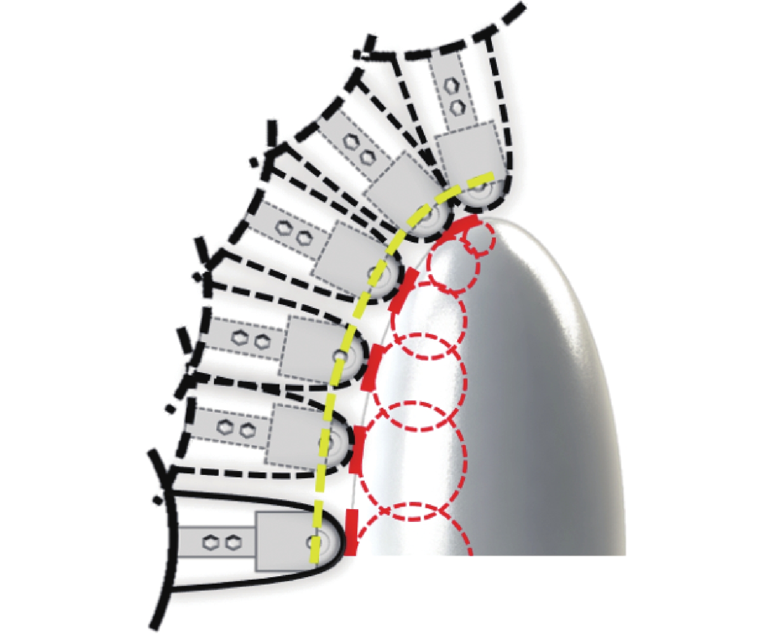
机器人辅助轮带磨削作为一种确定性加工方式,为了保证加工过程的稳定性,需要稳定的去除函数。在自由曲面的轮带磨削加工中,由于其上各点的曲率是变化的,磨削工具要想保证始终垂直于接触面,进行法向跟随加工,其姿态必然会一直发生变化,如图2所示。

图 2 轮带磨削加工示意图
Figure 2. Schematic diagram of wheel belt grinding
在实际的轮带磨削加工过程中,受磨削装置本身悬臂结构重力的影响,当磨削工具发生姿态变化时,磨削装置接触轮末端输出压力会发生较为明显的变化,导致去除函数发生改变。因此,需要对机器人辅助轮带磨削进行力控制,在加工过程中保证输出法向压力的稳定,即需要对由悬臂结构自身重力带来的影响进行补偿。
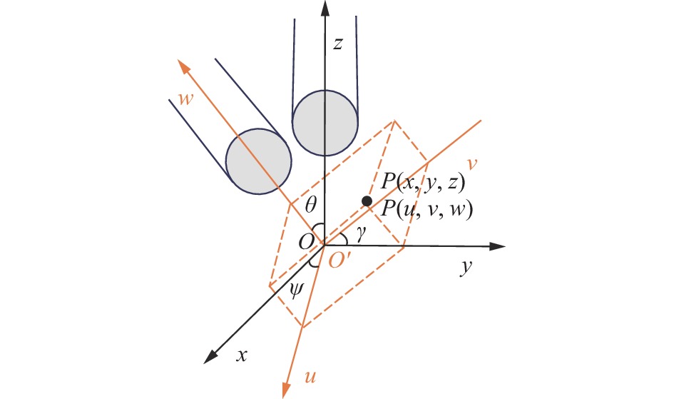
进行力控制首先需要对加工过程进行不同位置的受力分析,建立重力分量模型。如图3所示,以工件接触区域中心O为原点,以竖直方向为z轴建立固定坐标系O-xyz坐标系;当磨削工具以任意姿态接触工件表面时,以接触区域中心O′为原点,以磨削装置悬臂方向为w轴,建立工具坐标系O′-uvw坐标系。当两坐标系只发生相对转动时,可视为O-xyz固定坐标系分别绕z轴旋转$\psi $角度,绕y轴旋转$\theta $角度,绕x轴旋转$\gamma $角度后,得到O′-uvw工具坐标系。

图 3 末端执行器姿态描述
Figure 3. Attitude description of end effector
任意空间矢量$ \vec p $在固定坐标系和工具坐标系中可分别表示为$\overrightarrow {OP} $和$\overrightarrow {O'P} $,两个空间矢量的关系如下:
$$ \overrightarrow {OP} = R \cdot \overrightarrow {O'P} $$ (1) 其中
$$ \begin{split} R =& {R_1} \cdot {R_2} \cdot {R_3}{\text{ }} = \left[ {\begin{array}{*{20}{c}} {\cos \psi }&{ - \sin \psi }&0 \\ {\sin \psi }&{\cos \psi }&0 \\ 0&0&1 \end{array}} \right]\\ & \left[ {\begin{array}{*{20}{c}} {\cos \theta }&0&{\sin \theta } \\ 0&1&0 \\ { - \sin \theta }&0&{\cos \theta } \end{array}} \right]\left[ {\begin{array}{*{20}{c}} 1&0&0 \\ 0&{\cos \gamma }&{ - \sin \gamma } \\ 0&{\sin \gamma }&{\cos \gamma } \end{array}} \right] \end{split}$$ (2) 考虑悬臂杆重力分量对输出压力的影响时,在固定坐标系中悬臂杆重力矢量可视为$\overrightarrow {OP} = {\left[ {0,0,G} \right]^{\rm{T}}}$。轮带磨削工具旋转任意角度后,重力矢量变成:
$$ \overrightarrow {O'P} = {R^{ - 1}}{\left[ {0,0,G} \right]^{\rm{T}}} = \left[ \begin{gathered} - G \cdot \sin \theta \\ G \cdot \cos \theta \cdot \sin \gamma \\ G \cdot \cos \theta \cdot \cos \gamma \\ \end{gathered} \right] $$ (3) 其中,重力矢量在工具坐标系中沿w方向的分量为:
$$ \overrightarrow {O'Pw} = G \cdot \cos \theta \cdot \cos \gamma $$ (4) 接触轮输出压力Foutput可以表示为:
$$ F_{output}=F_{cylinder}+G\cdot \mathrm{cos}\theta \cdot \mathrm{cos}\gamma -2F_{belt} $$ (5) 式中:$ F_{cylinder} $为主动气缸输出压力;$ F_{belt} $为磨削砂带张紧力;$G$为悬臂组件重力。
-
重力补偿控制系统由姿态传感器、执行元件、控制器等组成,以实现MQQTB10-10D低摩擦直线气缸输出压力的快速调整。重力补偿控制系统工作原理如图4所示,整个重力补偿系统基于自适应控制的工作原理,通过识别机器人的姿态变化,获取控制系统的输入与输出信号,对比当前输出值与期望输出值的偏差,并做出相应的决策,在线调整系统的输入信号,使系统输出值趋于期望值。具体的控制过程如下:重力补偿控制系统工作时,上位机与姿态传感器以及DA转换模块实时通信,接收由姿态传感器发出的角度变化信号,并根据重力补偿算法进行数据处理,进而给DA转换模块发出相应的信号使电气比例阀作出响应动作,控制电流并输出补偿后的气压值,实现MQQTB10-10D低摩擦直线气缸输出压力的稳定。

图 4 重力补偿系统工作原理
Figure 4. Working principle of gravity compensation system
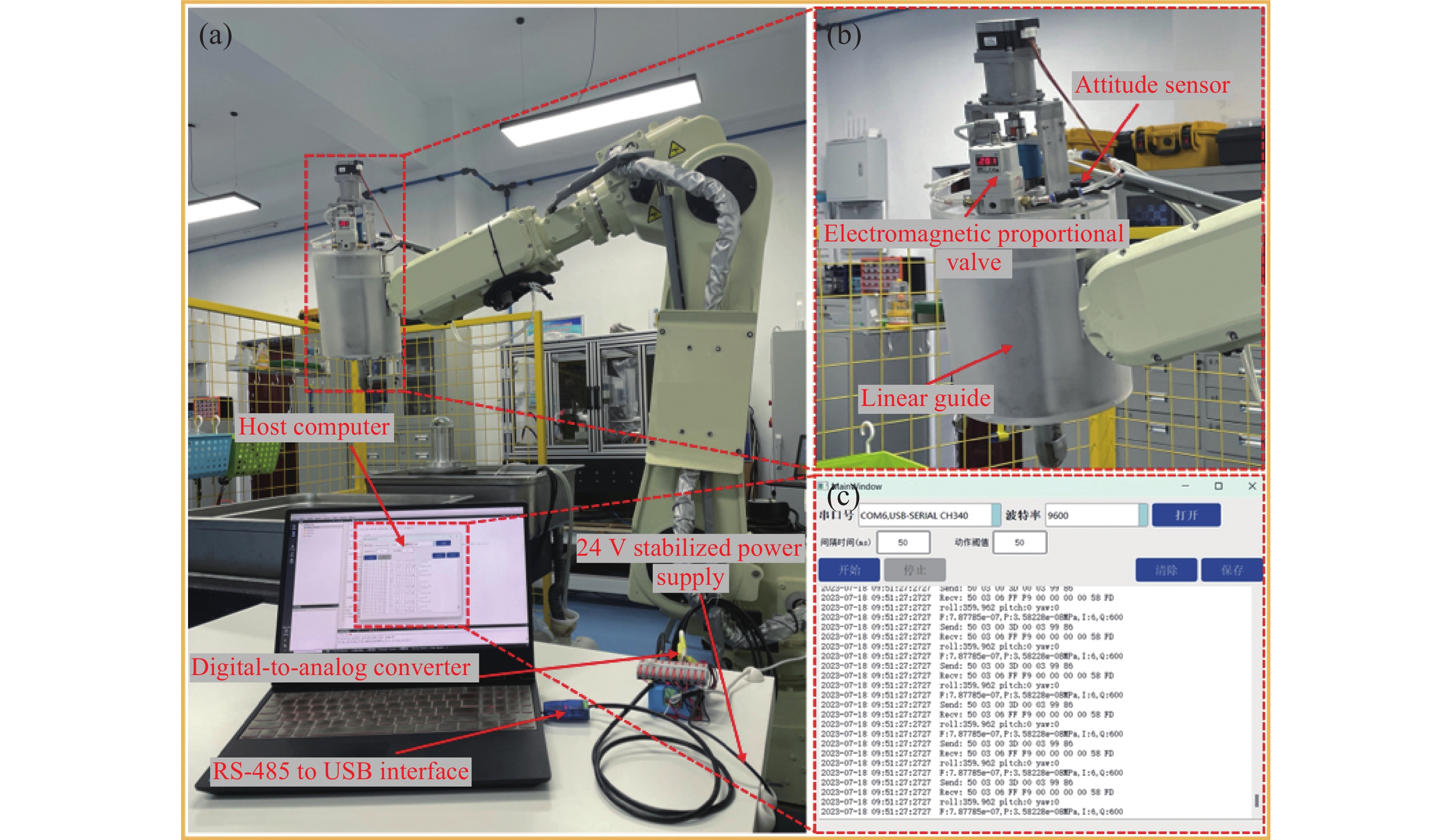
姿态传感器和电气比例阀安装在机器人末端轮带磨削工具的支撑组件上。六轴机械臂负载能力有限,因此在重力补偿系统硬件选型时要综合考虑其性能和质量。同时,要考虑上位机与下位机实现通信需要线路布局,选取的硬件必须尽可能简单、稳定且可靠。基于此,选用SINDT02倾角传感器作为姿态传感器,以低摩擦直线气缸为执行元件,以ITV2000电气比例阀和DAM-3202C转换模块、开发的上位机组成控制器,对气路、电路和软件控制方案进行正确设置,完成末端执行器重力变化补偿控制系统样机的硬件组装和软件调试。样机实物如图5所示。

图 5 重力补偿系统组成。(a) 末端执行器重力补偿控制系统;(b) 硬件布置;(c) 上位机
Figure 5. Components of a gravity compensation system. (a) Gravity compensation control system of end-effector; (b) Hardware layout; (c) Host computer
-
为了进行重力补偿系统的性能测试,需要对系统输出的恒力范围进行标定,如图6所示。公-自转机器人辅助轮带磨削装置可实现在0~63 N范围内的恒力输出。

图 6 输出压力标定
Figure 6. Output pressure calibrationt
磨削装置自身决定了输出恒力的范围,而上位机控制输出压力的精确性反映整个重力补偿系统性能,所以需要对装置绕X轴和Y轴旋转的重力补偿控制精度进行测试。如图7所示,电气比例阀设置常用的工作气压为0.2 MPa,操作机械臂示教器使轮带磨削工具进行旋转,绕X轴旋转记为Rx,绕Y轴旋转记为Ry。

图 7 性能测试实验示意图
Figure 7. Schematic diagram of performance test experiment
在重力补偿系统关闭状态下操作示教器使轮带磨削工具分别绕固定坐标系X轴、Y轴旋转0°~72°,每间隔9°记录测力仪的压力值分别为F1、F3。接通24 V稳压直流电源,分别给ITV2000电气比例阀和DAM-3202C转换模块供电,打开重力补偿控制系统上位机,运行软件控制程序,再次操作示教器,使轮带磨削工具分别绕固定坐标系X轴、Y轴旋转0°~72°,每间隔9°记录测力仪的压力值分别为F2、F4。记录实验数据如表1、表2所示。
表 1 绕X轴旋转输出压力对比
Table 1. Comparison of output pressure during rotation around the X-axis
Rx/(°) F1/N F2/N 0 19.75 19.75 9 19.45 19.75 18 18.95 19.55 27 18.49 19.52 36 17.73 19.68 45 16.60 19.60 54 16.50 19.68 63 15.64 19.56 72 15.21 19.39 表 2 绕Y轴旋转输出压力对比
Table 2. Comparison of output pressure during rotation around the Y-axis
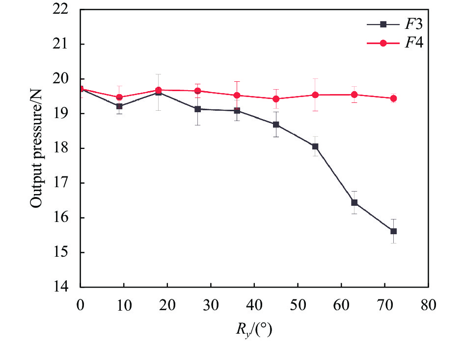
Ry/(°) F3/N F4/N 0 19.71 19.71 9 19.21 19.47 18 19.61 19.68 27 19.13 19.65 36 19.09 19.53 45 18.69 19.42 54 18.05 19.54 63 16.44 19.55 72 15.61 19.44 如图8所示,绕X轴旋转0°,0.2 MPa气压下输出19.75 N。无重力补偿时,输出压力随轮带磨削工具绕X轴旋转角度增大而衰减。在旋转72°时产生最大误差4.54 N,与旋转0°时输出压力相比,衰减22.99%。有重力补偿时,并未出现明显的压力衰减现象。在旋转72°时最大压力误差为0.36 N,与旋转0°时输出压力相比仅相差1.82%。

图 8 绕X轴旋转输出压力对比
Figure 8. Comparison of output pressure during rotation around the X-axis
如图9所示,绕Y轴旋转0°,0.2 MPa的气压输出19.71 N的压力。在无重力补偿时,输出压力随轮带磨削工具绕Y轴旋转角度增大而衰减。在旋转72°时产生最大误差4.10 N,与旋转0°的输出压力相比衰减20.80%。当重力补偿控制系统运行,有重力补偿时,并未出现明显的压力衰减现象。在旋转72°时最大压力误差为0.29 N,与旋转0°的输出压力相比,仅相差1.47%。

图 9 绕Y轴旋转输出压力对比
Figure 9. Comparison of output pressure during rotation around the Y-axis
当末端执行器姿态变化时,通过对有无重力补偿下输出压力的变化对比,发现文中设计的重力补偿控制系统有较好的补偿效果,能够在姿态变化过程中实现0~63 N范围输出压力的稳定性。同时,综合考虑SINDT02倾角传感器、ITV2000电气比例阀和DAM-3202C转换模块自身的响应频率高于100 Hz以及上位机读取写入的延时,通过测试,重力补偿装置响应时间小于300 ms。
-
根据图10建立坐标系,砂带绕Xt轴自转角速度为ωo,绕Zt轴公转角速度为ωe,磨削装置的自转和公转角速度矢量可以表示为:
$$ \overrightarrow{{\omega }_{x}}={\omega }_{{{o}}}\left(\mathrm{cos}\psi \cdot \mathrm{cos}\theta \text{,}\mathrm{sin}\psi \cdot \mathrm{cos}\theta \text{,}\mathrm{sin}\theta \right) $$ (6) $$ \begin{split} \overrightarrow {{\omega _z}} =& {\omega _{{e}}}( \cos \psi \cdot \sin \theta \cdot \cos \gamma + \sin \psi \cdot \sin \gamma ,\sin \psi \cdot \sin \theta \cdot \\ & \cos \gamma - \cos \psi \cdot \sin \gamma ,\cos \theta \cdot \cos \gamma ) \end{split} $$ (7) 
图 10 装置的速度分析示意图
Figure 10. Schematic diagram of velocity analysis of the device
Oo-XoYoZo光学元件坐标系中,点A(X,Y,Z)位置处的相应速度可以表示为相应角速度矢量和位置矢量的叉积。在接触区域中,只有磨削工具和光学元件表面之间的切向相对速度对去除函数有影响。因此,只需要考虑Xo轴和Yo轴方向的速度。Xo轴和Yo轴方向的切向速度为:
$$ \left\{ {\begin{array}{*{20}{c}} {{{\vec v}_{tx}} = \vec v \times {{\vec n}_{tx}} = \dfrac{1}{{\sqrt {1 + {{\left(\dfrac{{\partial z}}{{\partial x}}\right)}^2}} }}\left({v_x} + {v_z}\dfrac{{\partial z}}{{\partial x}}\right)} \\ {{{\vec v}_{ty}} = \vec v \times {{\vec n}_{ty}} = \dfrac{1}{{\sqrt {1 + {{\left(\dfrac{{\partial z}}{{\partial y}}\right)}^2}} }}\left({v_y} + {v_z}\dfrac{{\partial z}}{{\partial y}}\right)} \end{array}} \right. $$ (8) 式中:$ \vec v $=(vx,vy,vz)为自转和公转线速度的矢量和;$ {\vec n_{tx}} $和$ {\vec n_{ty}} $分别为Xo轴和Yo轴的单位矢量。因此,A(X,Y,Z)在接触区域任意一点的速度分布为:
$$ v\left( {x,y} \right) = \sqrt {{v_{tx}}^2 + {v_{ty}}^2} $$ (9) 最终可得到简化后的相对速度分布模型为:
$$ v\left( {x,y,t} \right) = \sqrt {{{\left( { - {\omega _o}{R_1}\sin {\omega _e}t - {\omega _e}y} \right)}^2} + {{\left( {{\omega _o}{R_1}\cos {\omega _e}t + {\omega _e}x} \right)}^2}} $$ (10) 其中
$$ {R_1} \approx \sqrt {{R^2} - {r^2}} $$ 式中:R为接触轮半径;r为接触区域半径。
-
在公转-自转轮带磨削装置的磨削过程中,磨削砂带被接触轮的压力贴合在光学元件的表面上。然而,由于接触轮的表面硬度比磨削砂带的表面硬度小得多,接触问题可以简化为接触轮和光学元件之间的接触。此时,总接触压力F可以定义为[19]:
$$ F = {\vec Z_t} \cdot {\vec Z_o} \oiint_S {P(x,y){\rm{d}}x{\rm{d}}y} $$ (11) 式中:$ {\vec Z_t} $为自转轴的方向矢量;$ {\vec Z_o} $为公转轴的方向矢量;P(x, y)为压强分布模型。
根据赫兹接触理论,接触轮和光学元件在压力下会形成一个三维椭圆接触区域。椭圆形接触区域中的压强分布遵循公式(12)[19]:
$$ P\left( {x,y} \right) = \frac{{3{F_{}}}}{{2\pi ab}}{\left[ {1 - \left( {\frac{{{x^2}}}{{{a^2}}} + \frac{{{y^2}}}{{{b^2}}}} \right)} \right]^{\tfrac{3}{2}}} $$ (12) 式中:a为椭圆区域的长轴;b为椭圆区域的短轴。
-
据广义Preston方程,根据之前建立的砂带磨削装置的磨削压强分布和速度分布模型,对其进行积分可以得到时间t内的材料去除量z(x,y)[20]:
$$ z\left( {x,y} \right) = K\int_0^t {P{{\left( {x,y} \right)}^\alpha }v{{\left( {x,y,t} \right)}^\beta }{\rm{d}}t} $$ (13) 式中:K为广义Preston系数;P(x, y)为接触区域的压强分布;v(x, y, t)为接触区域的速度分布;α为压力拟合系数,β为速度拟合系数。对z(x, y)进一步计算得到去除函数R(x,y):
$$ \begin{split} R\left(x,y\right)=&{K}_{I}{\left[1-\left(\frac{{x}^{2}}{{a}^{2}}+\frac{{y}^{2}}{{b}^{2}}\right)\right]}^{\tfrac{3\alpha }{2}}\times\\ &{\int }_{0}^{t}{[{\left({\omega }_{o}{R}_{1}\right)}^{2}+{\left({\omega }_{e}r\right)}^{2}+2{\omega }_{o}{\omega }_{e}{R}_{1}\left(x \cos\left({\omega }_{e}t\right)+\right.}\\ & {\left. y \sin\left({\omega }_{e}t\right)\right)]}^{\tfrac{\beta }{2}}{\rm{d}}t \end{split} $$ (14) 式中:${K_I} = \dfrac{{KP}}{T}$;$P = \dfrac{{5 F}}{{2\pi ab}}$。
去除函数的仿真结果如图11所示。

图 11 去除函数仿真结果
Figure 11. Simulation results of removal function
-
基于上述理论建模和求解出的去除函数,为了验证轮带磨削工具对光学曲面的修形能力,对碳化硅(SiC)曲面和硫化锌(ZnS)非球面进行磨削实验。正弦曲面的截面线公式可以表示为:
$$ z=-0.005 \sin \left(\frac{\pi x}{5}\right) $$ (15) x的取值范围是[0, 20] mm,y的取值范围是[0, 20] mm,加工后的理想正弦曲面如图12所示。

图 12 理想正弦曲面
Figure 12. Ideal sine surface
用GBS SmartWLI 白光干涉仪检测初始表面,如图13所示,Ra值为0.168 μm,表面质量较差。

图 13 碳化硅初始表面轮廓
Figure 13. Initial surface profile of SiC
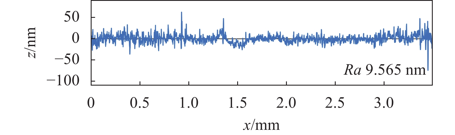
首先采用3 μm粒度金刚石砂带,主动气缸压力设置为0.28 MPa,砂带线速度为350 mm/s,冷却液采用1∶20稀释的金刚石磨削冷却液,对初始平面进行平面加工修形。加工后的碳化硅平面白光检测结果如图14所示,Ra值为9.565 nm。

图 14 碳化硅平面修型后表面轮廓
Figure 14. Surface profile of SiC after plane modification
以加工修形后的碳化硅平面为初始平面加工正弦曲面,主动气缸压力设置为0.28 MPa,砂带线速度为350 mm/s,冷却液采用1∶20稀释的金刚石磨削冷却液,分别采用3 μm和1 μm粒度金刚石砂带迭代两次进行修形加工。计算轮带磨削去除余量分布,如图15所示。通过驻留时间算法生成光栅路径扫描轨迹机械臂数控文件并导入机械臂控制器。

图 15 加工去除余量分布
Figure 15. Distribution of machining removal allowance
对加工后的工件采用轮廓仪测量,使用数据处理软件对比理论轮廓和实际轮廓,结果如图16所示。正弦曲面的最终加工PV值为1.414 μm。

图 16 加工后检测轮廓
Figure 16. Inspection profile after machining
待加工硫化锌非球面的方程如公式(16)所示,非球面参数如表3所示。
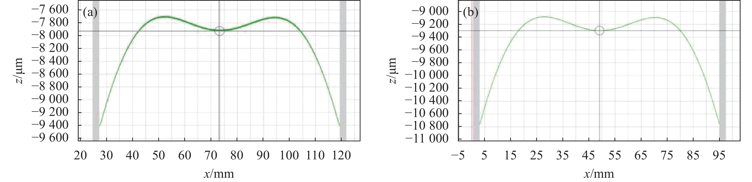
$$ Z = \frac{{{{c}}{{{y}}^2}}}{{R(1 + \sqrt {1 - (1 + K){\text{c}}{y^2}} )}} + A{y^4} + B{y^6} + C{y^8} + D{y^{10}} $$ (16) 如图17(a)所示,用Taylor Hobson PGI 1240轮廓仪进行检测,硫化锌非球面的面形误差如图18所示,其初始面型PV值为8.4 μm,Ra值为0.492 μm。
在修形算法中导入硫化锌非球面的轮廓测量数据,采用8000#氧化铝磨削带,配合20 nm粒度的二氧化硅抛光液进行磨削加工,公转速度40 r/min,气缸压力为2 N。如图17(b)所示,修形后硫化锌非球面的面形轮廓与初始面形轮廓相比数据波动明显降低,PV值收敛至2.7 μm,表面轮廓粗糙度显著降低,Ra值收敛到10.2 nm,图19为修形加工后的硫化锌非球面。
表 3 硫化锌非球面参数
Table 3. ZnS aspheric parameters
R c K A B C D 509.25 0.001 963 7 0 −1.273 631E-06 3.062 490E-10 −4.732 41E-14 4.979 344E-18 
图 17 轮廓仪检测图像。(a) 硫化锌非球面初始面形轮廓;(b) 硫化锌非球面修形后面形轮廓
Figure 17. Profile gauge inspection image. (a) Initial profile of aspheric ZnS surface; (b) Surface profile of aspheric ZnS after machining

图 18 硫化锌非球面的面形误差
Figure 18. Surface error of ZnS aspherical surface

图 19 修形后的硫化锌非球面
Figure 19. Aspheric ZnS after machining
通过对碳化硅曲面和硫化锌非球面的加工表明,在公自转轮带磨削工具与所设计的重力补偿系统协同作用下,能够有效地提升复杂曲面元件的表面质量。
-
文中对机器人辅助轮带磨削加工系统的公-自转轮带磨削工具建立恒力加载系统,完成轮带磨削工具的去除函数建模,并通过工艺实验及工艺仿真验证机器人辅助轮带磨削的可行性与可靠性,研究获得结果如下:
1) 设计了一种基于姿态传感器的重力补偿系统。通过坐标系变换,分析了轮带磨削工具任意姿态下末端执行器重力分量对加工工件接触区域输出压力的影响。通过实验验证,轮带磨削工具绕固定坐标系旋转0~72°情况下,能够实现0~63 N范围内的恒力输出,其中气缸气压为0.2 MPa时,最大压力波动在1.82%以内,重力补偿系统的响应时间小于300 ms。
2) 根据设计的砂带磨削装置的结构和加工方法,对压强分布和速度分布进行了分析。对该装置的磨削加工过程中的去除函数进行了求解和模拟。
3) 对常压烧结碳化硅和硫化锌非球面进行了轮带磨削加工,其中碳化硅的Ra值从0.168 μm收敛至9.565 nm,加工后的正弦曲面PV值为1.414 μm,硫化锌非球面的Ra值由0.492 μm收敛至10.2 nm,PV值由8.4 μm收敛到2.7 μm,验证了轮带磨削工具的加工稳定性和加工算法的合理性。
Design of gravity compensation and machining process for robotic belt grinding (invited)
-
摘要: 机器人辅助轮带磨削是一种基于计算机控制光学成形技术的确定性加工方法,具有成本低、柔性好、智能程度高且操作空间大的优点,因此机器人辅助轮带磨削作为一种较低成本的高精度、多自由度加工方法逐渐受到关注。文中介绍了所设计的机器人辅助轮带磨削系统结构及其加工原理,装置通过气动系统进行输出压力的柔顺控制。研究了任意加工姿态下机器人辅助轮带磨削中的恒力加载问题,分析了轮带磨削工具悬臂组件重力分量对其末端输出接触力的影响,建立了末端执行器的重力分量模型,并提出了基于姿态传感器的重力补偿控制方法,能够实现0~63 N范围内的恒力控制,并且最大压力波动小于1.82%,重力补偿系统的响应时间小于300 ms,实现了轮带磨削工具在任意姿态下的恒力加载。最后,根据Hertz接触理论和Preston方程完成了磨削工具在工件接触区域内的压强分布和速度分布分析,建立了轮带磨削工具的去除函数模型,并对碳化硅曲面与硫化锌非球面进行修形磨削实验,验证了装置加工的稳定性。Abstract:
Objective The application of complex surfaces in aerospace, optical engineering, shipbuilding, and other fields is becoming increasingly widespread. The surface roughness of complex surface components directly affects their performance, efficiency, and lifespan. Improving the surface quality of complex surface components has a significant impact on enhancing their operational performance. The substantial demand for high-precision machining imposes higher requirements on the surface accuracy and complexity of related optical elements. To address the challenges in machining difficult optical elements, such as processing deep cavities and high steepness optical components, this paper proposed a robot-assisted wheel abrasive belt grinding method. Additionally, a gravity compensation system for the wheel abrasive belt grinding device was designed, and the constant force loading and smooth control problems in robot-assisted wheel abrasive belt grinding under arbitrary processing orientations were investigated. Methods This paper proposed a robot-assisted wheel abrasive belt grinding method (Fig.1) and analyzed the influence of the end effector's gravity component on the output pressure. A gravity compensation system for the wheel abrasive belt grinding device was designed (Fig.4), and a physical prototype of the device was built (Fig.5). The performance of the gravity compensation system was tested. Based on Hertz contact theory and Preston equation, the removal function of the wheel abrasive belt grinding device was established (Fig.11). The effectiveness of the device was validated through grinding experiments on a sinusoidal silicon carbide (SiC) surface (Fig.16) and a zinc sulfide (ZnS) aspheric surface (Fig.19). Results and Discussions Due to the influence of the gravity from the cantilever structure of the grinding device itself, when the grinding tool undergoes changes in posture, the output pressure at the end of the grinding device's contact wheel will experience noticeable variations. To address this, we established a model for the gravity component of the cantilever and designed a gravity compensation system. During the operation of the gravity compensation control system, real-time communication was established between the upper computer, attitude sensor, and DA conversion module. The system received angle change signals from the attitude sensor and processed the data using the gravity compensation algorithm. Subsequently, the system sent corresponding signals to the DA conversion module, triggering the electrical proportional valve to respond, control the current, and output the compensated air pressure, thus achieving a stable control of the output pressure for the MQQTB10-10D low-friction linear cylinder. The system was capable of achieving constant force control within the range of 0-63 N (Fig.6), with maximum pressure fluctuations less than 0.36 N. The response time of the gravity compensation system was less than 300 ms, enabling constant force loading of the wheel abrasive belt grinding tool under arbitrary postures. Conclusions In this paper, a constant force loading system was established for the public-self-rotation wheel abrasive belt grinding tool of the robot-assisted wheel abrasive belt grinding system. A gravity compensation system based on attitude sensors was designed. The wheel belt grinding process was applied to both atmospheric pressure sintered SiC and ZnS aspheric surfaces. For SiC, the Ra value decreased from 0.168 μm to 9.565 nm after machining, resulting in a sinusoidal surface with a PV value of 1.414 μm. As for ZnS aspheric, the Ra value reduced from 0.492 μm to 10.2 nm, and the PV value converged from 8.4 μm to 2.7 μm after the grinding process. This validated the processing stability of the wheel abrasive belt grinding tool and the rationality of the grinding algorithm. The study can provide theoretical guidance for robot-assisted grinding of complex surface optical elements and hold practical value in this field. -
图 1 轮带磨削装置及原理示意图。(a) 悬臂组件;(b) 公-自转轮带磨削装置;(c) 装置工作原理
Figure 1. Schematic diagram of wheel belt grinding device and principle. (a) Cantilever component; (b) Rotation-revolution abrasive belt grinding device; (c) Device working principle
图 5 重力补偿系统组成。(a) 末端执行器重力补偿控制系统;(b) 硬件布置;(c) 上位机
Figure 5. Components of a gravity compensation system. (a) Gravity compensation control system of end-effector; (b) Hardware layout; (c) Host computer
图 8 绕X轴旋转输出压力对比
Figure 8. Comparison of output pressure during rotation around the X-axis
图 9 绕Y轴旋转输出压力对比
Figure 9. Comparison of output pressure during rotation around the Y-axis
图 17 轮廓仪检测图像。(a) 硫化锌非球面初始面形轮廓;(b) 硫化锌非球面修形后面形轮廓
Figure 17. Profile gauge inspection image. (a) Initial profile of aspheric ZnS surface; (b) Surface profile of aspheric ZnS after machining
表 1 绕X轴旋转输出压力对比
Table 1. Comparison of output pressure during rotation around the X-axis
Rx/(°) F1/N F2/N 0 19.75 19.75 9 19.45 19.75 18 18.95 19.55 27 18.49 19.52 36 17.73 19.68 45 16.60 19.60 54 16.50 19.68 63 15.64 19.56 72 15.21 19.39  下载: 导出CSV
表 2 绕Y轴旋转输出压力对比
Table 2. Comparison of output pressure during rotation around the Y-axis
Ry/(°) F3/N F4/N 0 19.71 19.71 9 19.21 19.47 18 19.61 19.68 27 19.13 19.65 36 19.09 19.53 45 18.69 19.42 54 18.05 19.54 63 16.44 19.55 72 15.61 19.44
下载: 导出CSV
表 3 硫化锌非球面参数
Table 3. ZnS aspheric parameters
R c K A B C D 509.25 0.001 963 7 0 −1.273 631E-06 3.062 490E-10 −4.732 41E-14 4.979 344E-18
下载: 导出CSV
-
[1] Sharma A, Kalsia M, Uppal A S, et al. Machining of hard and brittle materials: A comprehensive review [J]. Materials Today: Proceedings, 2022, 50(5): 1048-1052. doi: https://doi.org/10.1016/j.matpr.2021.07.452 [2] 李世杰, 徐超, 黄岳田, 王守义, 刘卫国. 车削加工硫化锌晶体工艺[J]. 红外与激光工程, 2020, 49(7): 20190567. doi: 10.3788/IRLA20190567 Li Shijie, Xu Chao, Huang Yuetian, et al. Processing technology of cutting ZnS crystal [J]. Infrared and Laser Engineering, 2020, 49(7): 20190567. (in Chinese) doi: 10.3788/IRLA20190567 [3] Xie Hailong, Li Jingrong, Liao Zhaoyang, et al. A robotic belt grinding approach based on easy-to-grind region partitioning [J]. Journal of Manufacturing Processes, 2020, 56(A): 830-844. doi: https://doi.org/10.1016/j.jmapro.2020.03.051 [4] Zhou Kun, Xu Jiayu, Xiao Guijian, et al. Enhancing ductile removal of Cf/SiC composites during abrasive belt grinding using low-hardness rubber contact wheels [J]. Ceramics International, 2022, 48(18): 26042-26054. doi: https://doi.org/10.1016/j.ceramint.2022.05.286 [5] Yang Rui, Yun Yu, Liu Ziwei, et al. Study on wheeled polishing technology based on industrial robot [J]. Opto-Electronic Engineering, 2018, 45(5): 170710. (in Chinese) doi: 10.12086/oee.2018.170710 [6] 周俊锋, 李盛良, 茅卫东等. 铣削机器人加工系统开发与应用[J]. 汽车工艺师, 2023(8): 42-45. doi: 10.16173/j.cnki.ame.2023.08.011 [7] Yang Jixiang, Chen Haiqing, Qi Ruibin, et al. A novel approach to robotic grinding guaranteeing profile accuracy using rigid-flexible coupling force control for free-formed surfaces [J]. CIRP Annals-Manufacturing Technology, 2023, 72(1): 313-316. [8] 唐洋洋, 丁金华, 王嘉循等. 机器人柔性砂带磨削加工力控制研究与应用[J]. 制造技术与机床, 2017(05): 97-102+106. doi: 10.19287/j.cnki.1005-2402.2017.05.018 Tang Yangyang, Ding Jinhua, Wang Jiaxun, et al. Force control research and application of robot flexible abrasive belt grinding [J]. Manufacturing Technology & Machine Tool, 2017(5): 97-102, 106. (in Chinese) doi: 10.19287/j.cnki.1005-2402.2017.05.018 [9] Bambrick S, Bechtold M, DeFisher S, et al. Recent developments in finishing of deep concave, aspheric, and plano surfaces utilizing the ultraform 5-axes computer controlled system[C]//Window and Dome Technologies and Materials XI, International Society for Optics and Photonics, 2009, 7302: 73020U. [10] Chen Fulei, Peng Xiaoqiang, Lai Tao, et al. Modeling and simulation of removal function for dual-axis wheel polishing [J]. Journal of Physics: Conference Series, 2023, 2463(1): 012044. doi: 10.1088/1742-6596/2463/1/012044 [11] 张国龙, 张杰, 蒋亚南等. 机器人力控末端执行器综述[J]. 工程设计学报, 2018, 25(06): 617-629. Zhang Guolong, Zhang Jie, Jiang Yanan, et al. Review of robotic end-effector with fore control [J]. Chinese Journal of Engineering Design, 2018, 25(6): 617-629. (in Chinese) [12] Ahn J H, Shen Y F, Kim H F, et al. Development of a sensor information integrated expert system for optimizing die polishing [J]. Robotics and Computer Integrated Manufacturing, 2001, 17(4): 269-276. [13] 陈祥. 球形公自转抛光工具系统设计及加工工艺研究[D]. 电子科技大学, 2018. Chen Xiang. Study on design and processing technology of spherical combined self-rotation and co-rotationmovement polishing tool[D]. Chengdu: University of Electronic Science and Technology of China, 2018. (in Chinese) [14] 常浩, 叶继飞, 陈粤, 周伟静. 用于微推力测量的电磁恒力特性研究[J]. 红外与激光工程, 2019, 48(S1): 142-146. Chang Hao, Ye Jifei, Chen Yue, et al. Characteristics of electromagnetic constant force for micro-thrust measurement [J]. Infrared and Laser Engineering, 2019, 48(S1): S117011. (in Chinese) [15] Mohammad K E A, Hong J, Wang D. Design of a force-controlled end-effector with low-inertia effect for robotic polishing using macro-mini robot approach [J]. Robotics and Computer Integrated Manufacturing, 2018, 49: 54-65. doi: 10.1016/j.rcim.2017.05.011 [16] Hong J, Mohammad K E A, Wang D. Improved design of the end-effector for macro-mini robotic polishing systems[C]//Proceedings of the 3rd International Conference on Mecha-tronics and Robotics Engineering, 2017: 36-41. [17] 马文超. 机器人打磨恒力控制装置设计研究[D]. 武汉: 华中科技大学, 2020. Ma Wenchao. Design and research on constant force control device for robot grinding[D]. Wuhan: Huazhong University of Science & Technology, 2020. (in Chinese) [18] Jin M, Ji S, Pan Y, et al. Effect of downward depth and inflation pressure on contact force of gasbag polishing [J]. Precision Engineering, 2017, 47: 81-89. [19] Johnson K L. Contact Mechanics[M]. Cambridge: Cambridge University Press, 1987. [20] Mejia C D, Beaudoin S. A locally relevant prestonian model for wafer polishing [J]. Journal of the Electrochemical Society, 2003, 150(2): 96-102. -

 点击查看大图

计量
- 文章访问数: 171
- HTML全文浏览量: 44
- PDF下载量: 51
- 被引次数: 0

