


 下载:
下载:


-
精密位移测量技术是现代加工和科学研究中不可或缺的支撑技术,测量的量程和精度决定着制造的尺寸和精度。随着摩尔定律的持续推进,集成电路的尺寸越来越小,由此衍生出了各种不同的精密位移测量方法。其中,激光干涉仪[1−2]和光栅干涉仪[3−4]同时兼备大量程、高精度、测量速度快的特点,被广泛应用于各个生产领域的制造产业当中。
光栅位移测量系统以光栅作为量尺,光栅的周期作为测量基准,相比于仅以波长作为基准的激光干涉仪,光栅位移测量系统具有抗环境干扰、结构紧凑、易于嵌入机械结构的独特优势[5],被更广泛地应用于需要在复杂环境下实现高定位精度的系统[6−7]中,如ASML公司光刻机晶圆定位系统、复杂加工环境下的车床台面定位系统等。为了提高光栅干涉仪的位移测量精度和增大量程,后续有许多改进的光栅干涉仪结构,如提高光学细分数来提高位移测量分辨率,Y Lu等人在2016年提出了利用直角棱镜结构,通过多次衍射实现了24倍的光学信号细分[8];通过增大测量量程来改进光栅干涉仪测量范围,利用增加光栅的有效长度来增大位移测量量程[9−10];通过改进光栅干涉仪的光路结构来提高系统的稳定性,减少误差的产生,利用相干光的偏振特性和共光路结构提高测量系统的抗环境干扰能力[11],使用光纤传输减少装配过程中引起的系统误差[12]。虽然使用光纤传输可以减短空间光路从而减少装配误差,但光纤的光强传输效率以及光纤和耦合器对干涉信号的相位影响仍需进一步研究。在以往的研究中,光栅位移测量系统的装配误差通常都是在标量状态下进行展开,忽略了入射方位角对系统的影响。文中将基于光栅矢量衍射理论[13−14],针对在光栅干涉仪位移测量过程中出现的光栅与位移台以及读数头之间的姿态位置误差进行分析,通过分析三个维度的角度偏差量,对可能产生的位移测量误差进行分析说明,为后续装置的改进提供理论依据。
-
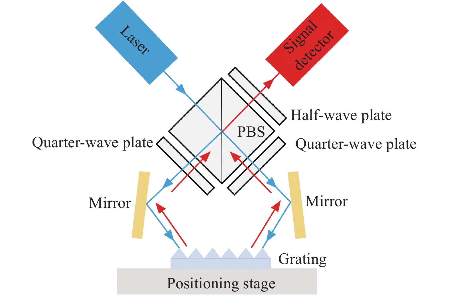
光栅干涉仪位移测量系统[15]主要由激光器、偏振分光棱镜、波片、位移台、光栅、反射镜、光电探测器等元件组成。激光器发出的光垂直入射至偏振分光棱镜(PBS),出射光变为两束互相垂直的线偏振光,其中透射光P光沿光束入射方向继续向前传播,反射光S光沿与光束入射方向垂直的方向继续向前传播,两束光经过四分之一波片后分别以Littrow角入射至光栅表面,其衍射光沿入射方向原路返回至偏振分光棱镜(PBS),由于光束两次经过四分之一波片,导致P偏振光变为S偏振光,S偏振光变为P偏振光,两束光经过偏振片后发生干涉,干涉信号被信号探测器接收。其光路结构如图1所示。

图 1 光栅干涉仪位移测量原理图
Figure 1. Schematic of grating interferometer displacement measurement
当光栅沿光栅矢量方向以一定速度v运动时,衍射光会产生多普勒频移,其频移的大小与光栅的运动速度、衍射级次成正比,与光栅的周期成反比,与入射到光栅的激光波长无关。设入射光的频率为$ {\omega }_{0} $,+1级衍射光的频率为$ {\omega }_{+1} $,−1级衍射光的频率为$ {\omega }_{-1} $,则:
$$ {\omega }_{+m}={\omega }_{0}-\frac{2\pi vm}{d} $$ (1) $$ {\omega }_{-m}={\omega }_{0}+\frac{2\pi vm}{d} $$ (2) 光栅左右两束衍射光的频差为:
$$ \Delta \omega ={\omega }_{-m}-{\omega }_{+m}=4\pi m\frac{v}{d} $$ (3) 根据差频干涉原理可知,当两束光发生干涉时,合成波的光强为:
$$ \begin{split} I&={A}^{2}= 4{a}^{2}{\cos}^{2}\left(\frac{{k}_{1}-{k}_{2}}{2}z-\frac{{\omega }_{1}-{\omega }_{2}}{2}t\right)=\\& 2{a}^{2}\mathrm{\cos}\left[\left({k}_{1}-{k}_{2}\right)z-\left({\omega }_{1}-{\omega }_{2}\right)t\right]+2{a}^{2} \end{split}$$ (4) 式中:$ {\omega }_{1}-{\omega }_{2} $即为两束光的频差。将公式(3)代入公式(4)可得:
$$ I \sim \mathrm{\cos}\left(4\pi m\frac{v}{d}\right)t = \mathrm{\cos}\left[4\pi m\frac{1}{d}{\int }_{0}^{t}v\left(t\right){\mathrm{d}}t\right] = \mathrm{c}\mathrm{o}\mathrm{s}\left(4\pi m\frac{x}{d}\right) $$ (5) 由公式(5)可以看出,当光栅沿着光栅矢量方向运动时,对称级次衍射光的干涉光强会随着位移的变化而发生明暗变化。令相位变化$ \Delta \varphi =4\pi mx/d $,则相位变化2π时,干涉光强明暗变化一次,光栅位移$ x=d/2 m $,这说明位移测量系统具有2m倍的光学细分。
-
在理想情况下,光栅干涉仪的位移测量结果是以核心部件光栅的周期作为基准,但是由于光栅、位移台、读数头、光学元件等系统模块的非理想装配,系统将会存在几何误差。而其中光栅和位移台的非理想装配以及光栅和读数头的非理想装配是导致系统几何误差的主要因素,本节将基于光栅矢量衍射理论就光栅位移测量系统的这两项误差成分逐项展开分析研究。
-
对于光栅位移测量系统,在理想装配情况下一维光栅的光栅矢量应与位移台的运动矢量方向一致,此时测得的光栅位移恰好为位移台的位移量。由于光栅在固定的过程中无法保证完美装配,使得光栅矢量与运动矢量之间出现偏差。为了清晰地描述光栅与位移台两者之间的相对位置关系,本节建立位移坐标系OXYZ以及光栅坐标系OX'Y'Z',其中OXYZ的X轴与位移台的运动矢量方向重合,OXZ平面为水平面,而OX'Y'Z'的X'轴与光栅矢量方向重合,OX'Z'平面为光栅矢量与光栅法线构成的平面。参考惯性导航领域中飞行器姿态表示方法,设一维光栅的横滚、俯仰和偏航角分别为α、β和γ,图2所示为三者共同描述了一维光栅相对于位移台的装配状态。
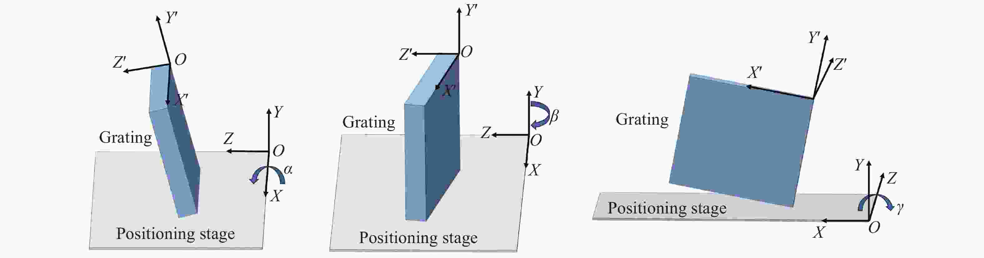
图 2 光栅相对位移台的装配状态图
Figure 2. Assembled state diagram of the grating relative displacement table
为规范起见,文中选用国际航空导航委员会推荐的旋转次序:首先令位移坐标系OXYZ绕Z轴旋转γ角,然后继续绕新的Y轴旋转β角,最后绕新的X轴旋转α角, 此时旋转后的位移坐标系OXYZ将与光栅坐标系OX'Y'Z'完全重合。对于依次沿Z、Y、X轴旋转γ、β、α角度,有:
$$ \left[\begin{array}{c}x\\ y\\ z\end{array}\right]=\left[\begin{array}{ccc}\cos\beta \cos\gamma & \sin\alpha \sin\beta \cos\gamma -\cos\alpha \sin\gamma & \cos\alpha \sin\beta \cos\gamma +\sin\alpha \sin\gamma \\ \cos\beta \sin\gamma & \sin\alpha \sin\beta \sin\gamma +\cos\alpha \cos\gamma & \cos\alpha \sin\beta \sin\gamma -\sin\alpha \cos\gamma \\ -\sin\beta & \sin\alpha \cos\beta & \cos\alpha \cos\beta \end{array}\right]\left[\begin{array}{c}{x}^{'}\\ {y}^{'}\\ {z}^{'}\end{array}\right] $$ (6) 设一维光栅一级衍射角为θ,单波长入射光P和Q分别以入射角θ和−θ对称入射到光栅表面,入射波矢量可以表示为:
$$ {\vec {k}}_{p}=-{k}_{0}\sin\theta {\vec {x}}^{'}-{k}_{0}\cos\theta {\vec {z}}^{'} $$ (7) $$ {\vec {k}}_{q}={k}_{0}\sin\theta {\vec {x}}^{'}-{k}_{0}\cos\theta {\vec {z}}^{'} $$ (8) 其中,根据Littrow条件$ {k}_{0}=\dfrac{\pi }{\lambda } $,$ \lambda =d\sin\theta $,出射波矢量可以表示为:
$$ {\vec {k}}_{pout}={k}_{0}\sin\theta {\vec {x}}^{'}+{k}_{0}\cos\theta {\vec {z}}^{'} $$ (9) $$ {\vec {k}}_{qout}={-k}_{0}\sin\theta {\vec {x}}^{'}+{k}_{0}\cos\theta {\vec {z}}^{'} $$ (10) 当一维光栅随位移台沿X方向发生位移:$ \vec {s}={s}_{x}\vec {x} $ 时,根据多普勒频移理论,P入射光的+1级衍射光与Q入射光的−1级衍射光由于光栅运动所引起的相位变化分别为:
$$ {\varphi }_{+1}=\left({\vec {k}}_{pout}-{\vec {k}}_{p}\right)\cdot \vec {s} $$ (11) $$ {\varphi }_{-1}=\left({\vec {k}}_{qout}-{\vec {k}}_{q}\right)\cdot \vec {s} $$ (12) 则测量信号相位差为:
$$ {\varphi }_{x}={\varphi }_{+1}-{\varphi }_{-1}=\frac{4\pi }{d}\cos\beta \cos\gamma {s}_{x} $$ (13) 利用已知的光栅周期d将其转化为位移值,得到系统最终的位移测量值为:
$$ {s}_{xm}=\cos\beta \cos\gamma {s}_{x} $$ (14) 理想装配情况下光栅绕Y'轴与Z'轴的旋转角均为零,此时的位移测量值恰好为光栅实际运动值$s_x$,由于误差角的存在,导致其产生测量误差:
$$ \Delta {s}_{xm}=\left(\cos\beta \cos\gamma -1\right){s}_{x} $$ (15) 从该结果可以看出,计量光栅装配非理想所引起的几何误差主要来自于其绕Y'轴与Z'轴的旋转误差角β和γ,而光栅绕X'轴旋转并不会引起额外的测量误差。并且从误差表达式中不难看出,误差角β和γ对测量误差的影响相同,根据该式,令一维光栅沿X方向的运动位移100 mm,可以做出相应图像,图3所示为模拟测量误差。

图 3 位移量为100 mm时的模拟测量误差
Figure 3. Analogue measurement error at a displacement of 100 mm
由此可以看出,俯仰角与偏航角对误差的影响相同,自然综合误差是由两个方向的误差叠加而成。该结论的前提条件是系统满足Littrow结构,此时系统误差相对比较明晰,但当系统不满足Littrow结构时,结论大概率会发生改变。
-
将光栅与位移台固定好之后,需要进行光学系统的组建。理想情况下两束入射光将在光栅矢量与光栅法线两者构成的平面内,以Littrow角对称入射到光栅表面上,而实际中由于装配水平的局限性,读数头相对于光栅通常无法进行精确装配,使得两者之间存在一定的装配误差。同时读数头内部光路结构也可能不理想致使读数头与光栅也存在相对误差。如图4所示,此时在光栅系下观察时,系统将不再满足Littrow结构,即入射光P与Q不再理想化,在入射角的基础上入射光又增加了入射方位角如图5所示,本节将在2.1节基础上继续分析此时读数系统的测量误差。

图 4 读数头装配误差图
Figure 4. Readhead assembly error diagram
为规范起见,这里同样选用国际航空导航委员会推荐的旋转次序:首先令位移坐标系OXYZ绕Z轴旋转γ角,然后继续绕新的Y轴旋转β角,最后绕新的X轴旋转α角,此时旋转后的位移坐标系OXYZ将与光栅坐标系OX'Y'Z'完全重合。在公式(6)中,令:
$$ {T}_{1}=\left[\begin{array}{ccc}\cos\beta \cos\gamma & \sin\alpha \sin\beta \cos\gamma -\cos\alpha \sin\gamma & \cos\alpha \sin\beta \cos\gamma +\sin\alpha \sin\gamma \\ \cos\beta \sin\gamma & \sin\alpha \sin\beta \sin\gamma +\cos\alpha \cos\gamma & \cos\alpha \sin\beta \sin\gamma -\sin\alpha \cos\gamma \\ -\sin\beta & \sin\alpha \cos\beta & \cos\alpha \cos\beta \end{array}\right] $$ (16) 设一维光栅一级衍射角为θ,单波长入射光Q和P分别以入射角θ1和-θ2入射到光栅表面,入射波矢量在位移坐标系可以表示为:
$$ {\vec {k}}_{q}={T}_{1}\cdot \left({k}_{0}\sin{\theta }_{1}\cos{\varPsi }_{1}{\vec {x}}^{'}+{k}_{0}\sin{\theta }_{1}\sin{\varPsi }_{1}{\vec {y}}^{'}-{k}_{0}\cos{\theta }_{1}{\vec {z}}^{'}\right) $$ (17) $$ {\vec {k}}_{p}={T}_{1}\cdot \left({-k}_{0}\sin{\theta }_{2}\cos{\varPsi }_{2}{\vec {x}}^{'}-{k}_{0}\sin{\theta }_{2}\sin{\varPsi }_{2}{\vec {y}}^{'}-{k}_{0}\cos{\theta }_{2}{\vec {z}}^{'}\right) $$ (18) 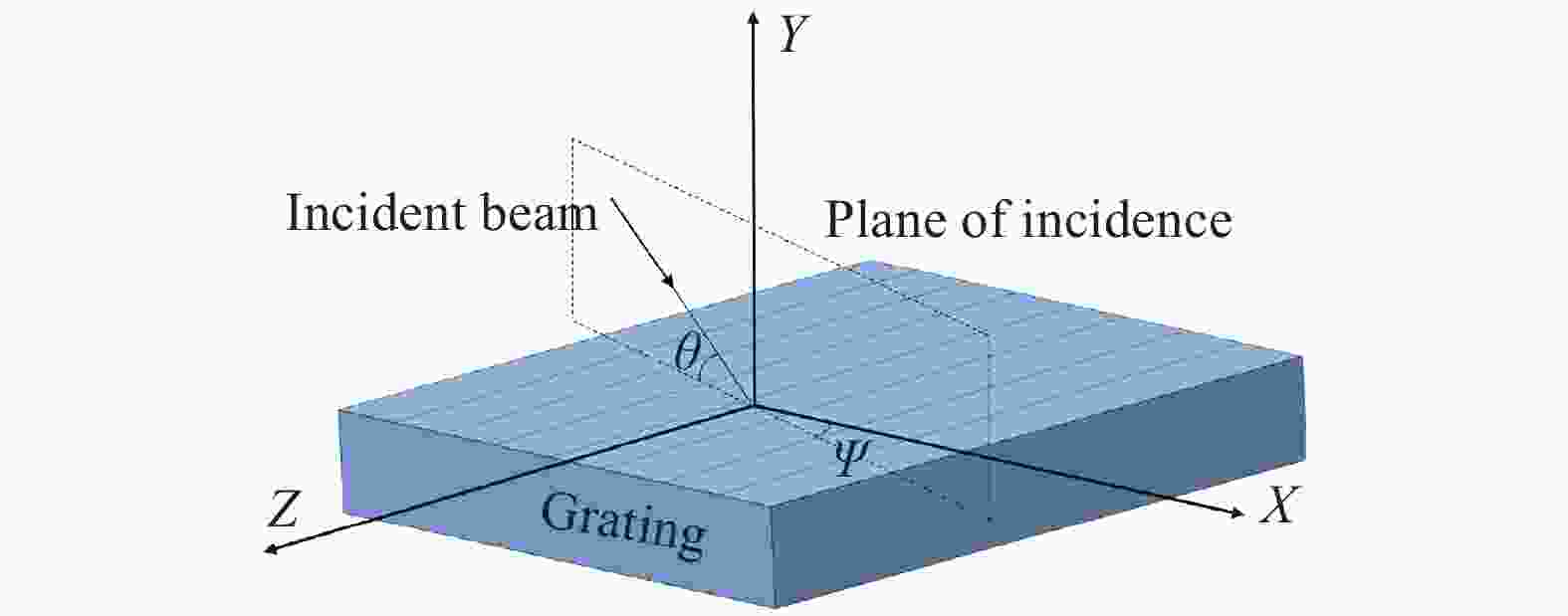
图 5 光栅矢量入射平面图
Figure 5. Grating vector incidence plane view
此时,系统已经不满足Littrow条件,出射波矢量可以表示为:
$$ \begin{split} {\vec {k}}_{qout}=&{T}_{1}\cdot \left({-k}_{0}\sin{\theta }_{m1}\cos{\varPsi }_{m1}{\vec {x}}^{'}-{k}_{0}\sin{\theta }_{m1}\sin{\varPsi }_{m1}{\vec {y}}^{'}+\right.\\& \left. {k}_{0}{z}_{m1}{\vec {z}}^{'}\right) \end{split} $$ (19) $$ \begin{split} {\vec {k}}_{pout}=&{T}_{1}\cdot \left({k}_{0}\sin{\theta }_{m2}\cos{\varPsi }_{m2}{\vec {x}}^{'}+{k}_{0}\sin{\theta }_{m2}\sin{\varPsi }_{m2}{\vec {y}}^{'}+\right.\\& \left.{k}_{0}{z}_{m2}{\vec {z}}^{'}\right) \end{split} $$ (20) 虽然,系统已经不满足Littrow条件,但仍满足广义一维光栅方程,因此有:
$$ \left\{\begin{array}{c}{k}_{0}\sin{\theta }_{m1}\cos{\varPsi }_{m1}=2m\dfrac{\pi }{d}-{k}_{0}\sin{\theta }_{1}\cos{\varPsi }_{1}\\ \begin{array}{c}{k}_{0}\sin{\theta }_{m1}\sin{\varPsi }_{m1}=-{k}_{0}\sin{\theta }_{1}\sin{\varPsi }_{1}\\ {k}_{0}\sin{\theta }_{m2}\cos{\varPsi }_{m2}=2m\dfrac{\pi }{d}-{k}_{0}\sin{\theta }_{2}\cos{\varPsi }_{2}\end{array}\\ {k}_{0}\sin{\theta }_{m2}\sin{\varPsi }_{m2}=-{k}_{0}\sin{\theta }_{2}\sin{\varPsi }_{2}\end{array}\right\} $$ (21) 当一维光栅伴随位移台沿X方向发生位移:$ \vec {s}={s}_{x}\vec {x} $,此时进一步进行拓展,不仅仅局限于$ m=1 $这一种情况,根据多普勒频移理论,P 入射光的+m级衍射光与Q入射光的-m级衍射光由于光栅运动所引起的相位变化分别为:
$$ {\varphi }_{+m}=\left({\vec {k}}_{pout}-{\vec {k}}_{p}\right)\cdot \vec {s} $$ (22) $$ {\varphi }_{-m}=\left({\vec {k}}_{qout}-{\vec {k}}_{q}\right)\cdot \vec {s} $$ (23) 即测量信号相位差为:
$$ \begin{split} & {\varphi }_{x} = {\varphi }_{+m} - {\varphi }_{-m} = \frac{4\pi m\cos\beta \cos\gamma }{d}{s}_{x} - \left({k}_{0}{z}_{m1} - {k}_{0}{z}_{m2} +\right.\\& \left.{k}_{0}\cos{\theta }_{1}- {k}_{0}\cos{\theta }_{2}\right)\left(\cos\alpha \cos\gamma \sin\beta +\sin\alpha \sin\gamma \right){s}_{x} \end{split} $$ (24) 利用已知的光栅周期d将其转化为位移值,得到系统最终的位移测量值为:
$$\begin{split} & {s}_{xm}=\cos\beta \cos\gamma {s}_{x}- \frac{d}{4\pi m}\left({k}_{0}{z}_{m1}-{k}_{0}{z}_{m2}+{k}_{0}\cos{\theta }_{1}-\right.\\& \left. {k}_{0}\cos{\theta }_{2}\right)\left(\cos\alpha \cos\gamma \sin\beta +\sin\alpha \sin\gamma \right){s}_{x} \end{split} $$ (25) 位移测量误差:
$$\begin{split} & {\Delta s}_{xm}=(\cos\beta \cos\gamma -1){s}_{x}- \frac{d}{4\pi m}\left({k}_{0}{z}_{m1}-{k}_{0}{z}_{m2}+{k}_{0}\cos{\theta }_{1}-\right.\\& \left.{k}_{0}\cos{\theta }_{2}\right)\left(\cos\alpha \cos\gamma \sin\beta +\sin\alpha \sin\gamma \right){s}_{x} \end{split} $$ (26) 结合2.1节不难发现,该结果是在2.1节结论基础上又增加了一项影响式,且该式与P光和Q光入射的波矢量以及三个误差角紧密相关。此时,若根据色散关系中相同介质波矢量大小相同,则有:
$$ {k}_{0}{z}_{m1}=\sqrt{{{k}_{0}}^{2}-{\left(\frac{2m\pi }{d}-{k}_{0}\sin{\theta }_{1}\cos{\varPsi }_{1}\right)}^{2}-{\left({k}_{0}\sin{\theta }_{1}\sin{\varPsi }_{1}\right)}^{2}} $$ (27) $$ {k}_{0}{z}_{m2}=\sqrt{{{k}_{0}}^{2}-{\left(\frac{2m\pi }{d}-{k}_{0}\sin{\theta }_{2}\cos{\varPsi }_{2}\right)}^{2}-{\left({k}_{0}\sin{\theta }_{2}\sin{\varPsi }_{2}\right)}^{2}} $$ (28) 从而解释了方位角Ψ对位移测量误差的影响结果,从该表达式中可以看出,当光栅周期d确定、$ k_{0} $确定,光栅级数m以及位移$ s_{x} $确定时,能够影响系统测量误差的只有三个误差角α、β、γ以及能够影响入射光P光和Q光的相对状态的角度θ1、θ2、Ψ1、Ψ2 。
根据前面对角度装配误差的理论分析,可得以下结论:
1)若影响入射光P光和Q光的相对状态的角度θ1、θ2相等,Ψ1、Ψ2相等,则此时误差与上一节类似,与α角无关。
2)但是,一般情况下影响入射光P光和Q光的相对状态的角度θ1、θ2、Ψ1、Ψ2往往不能相互抵消,此时在β,γ存在时,误差与α角有关。
3)如图6所示,对于β角,即使其他影响都不存在时,仍会对误差产生影响,其结果与2.1节类似;当其他影响存在时,如图7所示,对误差产生的影响曲线大致上不会改变。
4) γ角与β角对误差的影响大致相同,因此不再赘述。
因为影响入射光P光和Q光的相对状态的角度θ1、θ2、Ψ1、Ψ2是相对的,因此固定θ2、Ψ2,对θ1、Ψ1进行分析:
5)若三个误差角α、β、γ都为0时,根据公式不难得出,此时误差并不会存在。
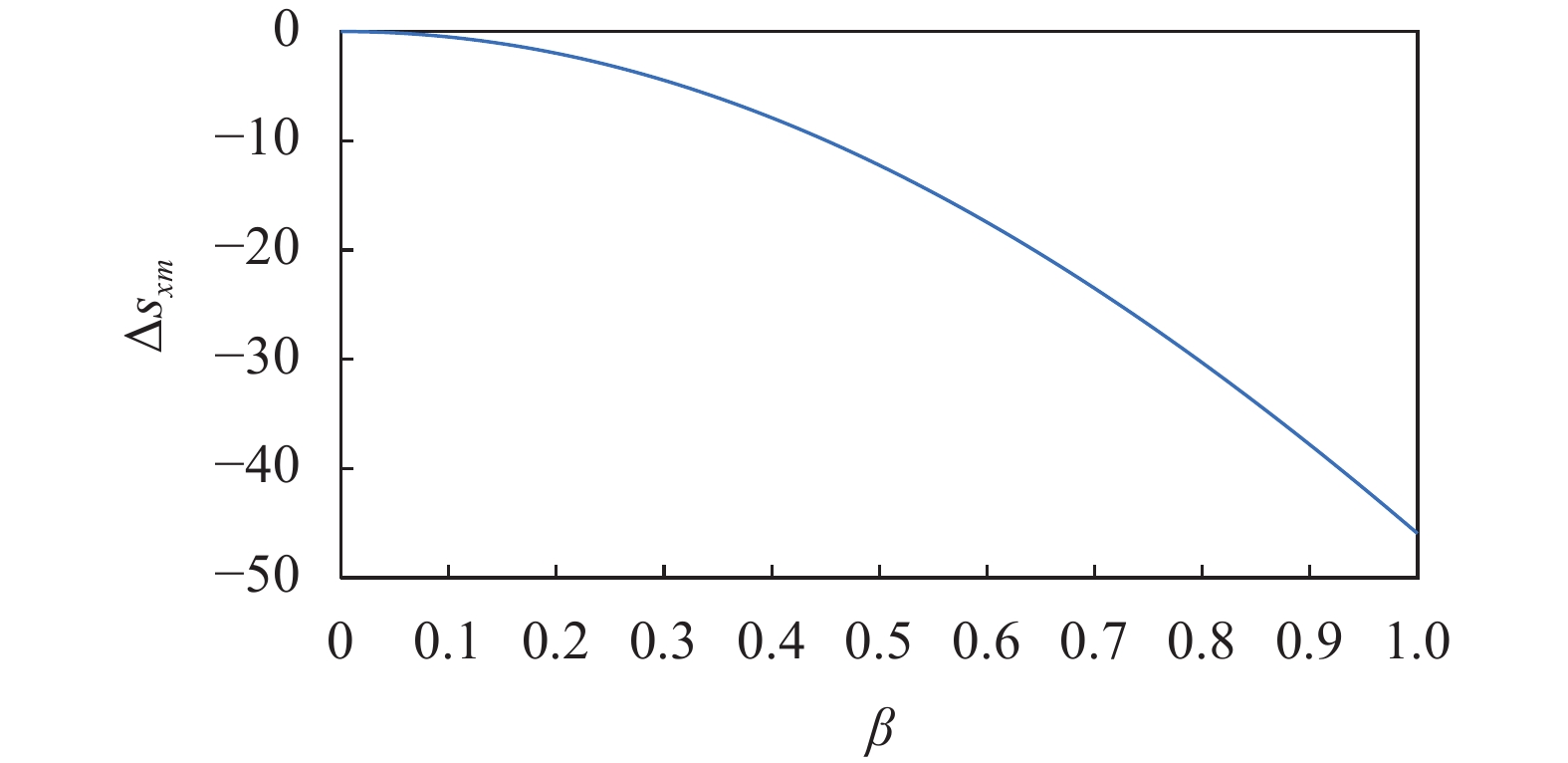
图 6 当其他影响不存在时β角对测量误差的影响
Figure 6. Effect of β-angle on measurement error when other effects are absent

图 7 当其他影响存在时β角对测量误差的影响
Figure 7. Effect of β-angle on measurement error when other effects are present
6)而当三个误差角α、β、γ存在时,发现θ1、Ψ1的存在值影响误差表达式的后一项,其对β、γ角曲线影响不大,只在α角度曲线出现明显变化。
本节在2.1节的基础上,研究了读数头装配误差,而它与2.1节光栅装配误差最大的区别便在于读数头装配误差导致系统不满足Littrow结构,使得问题进一步复杂。但正因如此,本节基于广义一维光栅方程,探究出了一个更为普遍的结论,并从该结论中分别讨论了系统测量误差与三个误差角α、β、γ以及影响入射光P光和Q光的相对状态的角度θ1、θ2、Ψ1、Ψ2之间的关系。
-
文中从光栅装配误差、读数头装配误差两个方面分析了在使用光栅位移测量系统时由于装夹问题导致的测量误差,对可能产生的位移测量误差进行了分析说明。在光栅干涉仪位移测量系统中,通过基于光栅矢量衍射理论的分析表明:当满足Littrow入射结构时,在横滚角、俯仰角、偏航角中横滚角α对测量结果不产生影响,并推导出了俯仰角β和偏航角γ对位移测量结果产生影响的表达式;当不满足Littrow入射结构时,激光斜入射后将会增加方位角,根据广义一维光栅方程,推导出了在方位角存在时一个更为普遍的结论,分析了系统测量误差与三个误差角α、β、γ以及影响入射光P光和Q光的相对状态的角度θ1、θ2、Ψ1、Ψ2之间的关系,为后续装置的改进提供理论依据。
Displacement measurement error of grating interferometer based on vector diffraction theory
-
摘要: 光栅干涉仪位移测量系统作为测量领域中最精密的测量仪器之一,由于在测量过程中光栅的姿态位置无法保证完美装配,使得光栅的光栅矢量方向与运动矢量方向之间出现偏差,导致位移测量结果出现周期性非线性误差。文中针对在光栅干涉仪位移测量过程中出现的光栅与位移台以及读数头之间的姿态位置误差进行分析,通过分别建立位移坐标系及光栅坐标系,参考惯性导航领域中飞行器姿态表示方法,利用一维光栅的横滚、俯仰和偏航角共同描述一维光栅相对于位移台的装配状态。通过基于矢量衍射理论分析光栅干涉仪位移测量时三个维度的角度偏差量,对可能产生的位移测量误差进行了分析说明。基于广义一维光栅方程,探究出了一个更为普遍的结论,为后续装置的改进提供理论依据,以提高系统的测量精度。Abstract:
Objective The grating interferometer displacement measurement system, as one of the most precise measuring instruments in the measurement field, is not able to ensure the perfect assembly of the grating's attitude position during the measurement process, which makes the deviation between the grating's grating vector direction and the motion vector direction, leading to the periodic nonlinear error in the displacement measurement results. In previous studies, the assembly error of grating displacement measurement system is usually unfolded in the scalar state, ignoring the effect of incident azimuth angle on the system. Based on the grating vector diffraction theory, this paper analyses the attitude position error between the grating and the displacement stage as well as the readhead that occurs during the displacement measurement of the grating interferometer, and illustrates the possible displacement measurement error by analysing the amount of angular deviation of the three dimensions, so as to provide the theoretical basis for the improvement of the subsequent device. Methods Ideally, the displacement measurement of a grating interferometer is based on the period of the core component, the grating. But due to the non-ideal assembly of the grating, the displacement stage, the readhead, the optics, and other system modules, there will be geometric errors in the system. The non-ideal assembly of the grating and the displacement stage, as well as the non-ideal assembly of the grating and the readhead, are the main factors leading to the geometrical error of the system. In this paper, we analyse the attitude position error between grating, displacement stage and readhead which occurs during the displacement measurement of grating interferometer, by establishing displacement coordinate system OXYZ and grating coordinate system OX'Y'Z', and referring to the attitude representation method of aircraft in the field of inertial navigation. We set the roll, pitch and yaw angles of one-dimensional grating to be α, β and γ respectively, which are common in describing the assembly state of the 1D grating relative to the translation stage. By analysing the amount of angular deviation in the three dimensions based on the grating vector diffraction theory, the possible displacement measurement errors are analysed and illustrated. Results and Discussions The results of the analyses of the grating assembly errors show that the geometrical errors caused by the non-ideal assembly of the metrology grating are mainly due to the rotational error angles β and γ around the Y' and Z' axes, while the rotation of the grating around the X' axes does not cause any additional measurement errors. It can be seen from the error expressions that error angles β and γ have the same effect on the measurement error. When analysing the readhead assembly error, it was found that the biggest difference between this and the encoder assembly error is that the readhead assembly error causes the system not to satisfy the Littrow structure, further complicating the problem. However, because of this, it explores a more general conclusion based on the generalised one-dimensional grating equations in this paper, from which the relationship between the systematic measurement error and the three error angles α, β and γ and the angles θ1, θ2, Ψ1, Ψ2 affecting the relative states of the incident P-light and Q-light is discussed respectively. Conclusions This paper analyses the measurement errors caused by clamping problems when using the grating displacement measurement system from two aspects of grating assembly errors and readhead assembly errors, and provides an analytical description of the possible displacement measurement errors. In the grating interferometer displacement measurement system, the analysis based on the grating vector diffraction theory shows that, when the Littrow incidence structure is satisfied, among the roll angle, pitch angle and yaw angle, the roll angle has no effect on the measurement results, and the expressions for the effects of pitch angle and yaw angle on the displacement measurement results are derived; When the Littrow incidence structure is not satisfied, the oblique incidence of laser light increases the azimuth angle. When the Littrow incidence structure is not satisfied, the laser will increase the azimuth angle after oblique incidence. According to the generalised one-dimensional grating equation, a more general conclusion in the presence of azimuth angle is deduced, which provides a theoretical basis for the subsequent improvement of the device. -
图 1 光栅干涉仪位移测量原理图
Figure 1. Schematic of grating interferometer displacement measurement
图 2 光栅相对位移台的装配状态图
Figure 2. Assembled state diagram of the grating relative displacement table
图 3 位移量为100 mm时的模拟测量误差
Figure 3. Analogue measurement error at a displacement of 100 mm
图 6 当其他影响不存在时β角对测量误差的影响
Figure 6. Effect of β-angle on measurement error when other effects are absent
-
[1] Pisani M. A homodyne Michelson interferometer with sub-picometer resolution [J]. Measurement Science and Technology, 2009, 20(8): 084008. doi: 10.1088/0957-0233/20/8/084008 [2] 王冬, 崔建军, 张福民, 等 . 用于微位移测量的迈克尔逊激光干涉仪综述 [J]. 计量学报,2021 ,42 (1 ):1 -8 . Wang D, Cui J, Zhang F, et al. Review of michelson laser interferometer for micro displacement measurement [J]. Acta Metrologica Sinica, 2021, 42(1): 1-8. (in Chinese)[3] Hu P, Chang D, Tan J, et al. Displacement measuring grating interferometer: A review [J]. Frontiers of Information Technology & Electronic Engineering, 2019, 20(5): 631-654. [4] 王磊杰, 张鸣, 朱煜, 等 . 超精密外差利特罗式光栅干涉仪位移测量系统 [J]. 光学精密工程,2017 ,25 (12 ):2975 -2985 . doi: 10.3788/OPE.20172512.2975 Wang L J, Zhang M, Zhu Y, et al. A displacement measurement system for ultra-precision heterodyne Littrow grating interferometer[J]. Optics and Precision Engineering, 2017, 25(12): 2975-2985. doi: 10.3788/OPE.20172512.2975[5] 李金鹏, 陈磊, 方波, 朱文华 . 动态干涉仪的位相光栅衍射效率研究 [J]. 红外与激光工程,2015 ,44 (9 ):2696 -2701 . Li Jinpeng, Chen Lei, Fang Bo, et al. Diffraction efficiencies of phase gratings based on dynamic interferometer [J]. Infrared and Laser Engineering, 2015, 44(9): 2696-2701. (in Chinese)[6] Seybold J, Bülau A, Fritz K P, et al. Miniaturized optical encoder with micro structured encoder disc [J]. Applied Sciences, 2019, 9(3): 452. doi: 10.3390/app9030452 [7] Zhang W, Wang Y, Du H, et al. High-precision displacement measurement model for the grating interferometer system [J]. Optical Engineering, 2020, 59(4): 045101. [8] Lu Y, Zhou C, Li S, et al. Study of a grating interferometer with high optical subdivision technique[C]//Holography, Diffractive Optics, and Applications VII. SPIE, 2016, 10022: 238-243. [9] Lu Y, Wei C, Jia W, et al. Two-degree-freedom displacement measurement based on a short period grating in symmetric Littrow configuration [J]. Optics Communications, 2016, 380: 382-386. doi: 10.1016/j.optcom.2016.06.016 [10] 刘林, 刘兆武, 于宏柱, 等 . 大量程高性能光栅位移测量技术 [J]. 计测技术,2023 ,43 (1 ):81 -90 . Liu Lin, Liu Zhaowu, Yu Hongzhu, et al. Large range and high performance grating displacement measurement technology [J]. Metrology & Measurement Technology, 2023, 43(1): 81-90. (in Chinese)[11] Hsieh H L, Lee J Y, Wu W T, et al. Quasi-common-optical-path heterodyne grating interferometer for displacement measurement [J]. Measurement Science and Technology, 2010, 21(11): 115304. doi: 10.1088/0957-0233/21/11/115304 [12] Zhu Y, Zhang M, Wang L, et al. Dual-frequency grating interferometer displacement measurement system: US, Patent 9885556[P]. 2018-02-06. [13] Zhou Guozun, Tian Weijian. Generation of cylindrical vector beams by using subwavelength grating polarizer [J]. Infrared and Laser Engineering, 2019, 48(3): 0320004. (in Chinese) doi: 10.3788/IRLA201948.0302004 [14] 郑青泉, 王春阳, 王子硕, 王增, 康丁 . 斜入射下液晶偏振光栅衍射特性研究 [J]. 红外与激光工 程,2022 ,51 (7 ):20210511 . doi: 10.3788/IRLA20210511 Zheng Qingquan, Wang Chunyang, Wang Zishuo, et al. Research on diffraction characteristics of liquid crystal polarization grating under oblique incidence [J]. Infrared and Laser Engineering, 2022, 51(7): 20210511. (in Chinese) doi: 10.3788/IRLA20210511[15] Kao C F, Lu S H, Shen H M, et al. Diffractive laser encoder with a grating in Littrow configuration [J]. Japanese Journal of Applied Physics, 2008, 47(3R): 1833. doi: 10.1143/JJAP.47.1833 -

 点击查看大图
计量
- 文章访问数: 90
- HTML全文浏览量: 27
- PDF下载量: 27
- 被引次数: 0

