


-
新型的机载吊舱已经开始使用柔性枢轴取代传统机械轴系,使用音圈执行器驱动,系统带宽明显提升[1]。柔性枢轴元件无法安装常规编码器等测角组件,因此需要研究载荷相对于基座的空间角度测量方法。
孙国燕[2]等利用两个相同的二维自准直仪成一定角度放置和一个反射部件组成三维姿态角测量传感器,两自准直仪相对空间布置精度较难保证,占用空间大,较难分离轴向平移对测量的影响,且测量范围有限。Li R[3]等提出了基于一种改进的立方体角反射器(MCCR)的大测量范围三自由度测角方法,选用COMS来接收反射光斑,测量范围虽大,但精度不高,COMS数据处理需花费大量时间,带宽较低,且受光斑质量影响较大。Wenran Ren[4]等提出了一种基于透射光栅和组合反射镜的激光自准直仪测角方法,使用三片位置敏感探测器(PSD)来读取由投射光栅产生的三束测量光束位置信息计算三轴角度值,该设计在较小的范围内拥有很高的精度,但测量范围小,难以集成,很多实际应用场景较难实现。上述每种测试方法的性能指标如表1所示。
文中提出一种新型基于双PSD的三维角度测量传感器,该三维测角方法拥有非接触、连续测量、高带宽、体积小、相对安装精度要求简单等优势,对轴向方向平移不敏感。对两片PSD的相对位置进行了标定,对采集的模拟信号抖动数据进行滤波处理,并进行了实验验证,实现了高精度、高稳定性的高速实时测量,该方法可广泛应用于工程实践中。
表 1 各三轴测角方法性能指标
Table 1. Performance indicators of each three-axis angle measurement methods
Specifications Dual autocollimation instrument type MCCR instrument type Three PSD grating type Angle measurement range ±2' ±10° ±360" Yaw angle measurement error 2.2" 394.16 " 0.013" Pitch angle measurement error 2.5" 455.36 " 0.012" Roll angle measurement error 8.7" 319.57" 0.009" -
二维PSD分为二面型、四边形、枕型等结构,而根据Gear定理为基础设计的枕型PSD[5-6]具有暗电流小、线性度高、各电极间相互影响小等优点。当光源照在PSD光敏面时,有效区域上的光斑位置会发生横向光电效应(Transverse Photoelectric Effect)[7],形成电势差从而产生光电流。如图1所示,当点光源照射到点O时,可将靶面分看为四份,面积分别为S1、S2、S3、S4 mm2,电极输出电流IY1、IX1、IY2、IX2分别为:
$$ {I}_{Y1}=\frac{{U}_{\alpha }}{S 1\times \rho } $$ (1) 
图 1 二维PSD结构示意图
Figure 1. Schematic diagram of 2D PSD structure
$$ {I}_{X1}=\frac{{U}_{\alpha }}{S 3\times \rho } $$ (2) $$ {I}_{Y2}=\frac{{U}_{\alpha }}{S 4\times \rho } $$ (3) $$ {I}_{X2}=\frac{{U}_{\alpha }}{S 2\times \rho } $$ (4) 式中:Uα为O点产生的光电势;PSD光敏靶面电阻呈均匀分布,密度为$\; \rho $(单位:Ω/mm2)。
L 为 PSD 相邻两电极间的长度,通过对四路电流信号的采集,可以计算出入射光照射到O点时的二维坐标位置。入射光点的位置坐标计算公式为:
$$ {X}=\frac{{L}}{2}\times \frac{({I}_{X2}+{I}_{Y1})-({I}_{X1}+{I}_{Y2})}{{I}_{X1}+{I}_{X2}+{I}_{Y1}+{I}_{Y2}} $$ (5) $$ {Y}=\frac{{L}}{2}\times \frac{({I}_{X2}+{I}_{Y2})-({I}_{X1}+{I}_{Y1})}{{I}_{X1}+{I}_{X2}+{I}_{Y1}+{I}_{Y2}} $$ (6) -
三维角度测量传感器主要由自准直测量单元和双面反射光楔两部分构成。如图2所示,自准直测量单元包括光源、PSD1、PSD2、自准直镜头以及后续处理电路。双面反射光楔前表面为半反半透面,后表面为全反射面。

图 2 双PSD三维测角原理图
Figure 2. Schematic diagram of dual PSD 3D angle measurement
将两片PSD布置在自准直镜头的焦面上,光源放置在两PSD中间,发射出的光束经自准直镜头后变成平行光照射到光楔上,一部分平行光束经光楔前表面直接反射后通过自准直镜头聚焦在PSD2上,另一部分经光楔前表面折射、后表面反射、前表面折射后通过自准直镜头聚焦在PSD1上。将PSD输出的微小电流信号通过处理电路转化成模拟电压信号,使用ADC转化成数字量,在MCU内计算位置坐标值信息。将两片PSD上的光斑位置,结合自准直透镜焦点距离以及两PSD相对位置关系,通过反射矩阵、折射矩阵以及斯涅耳定律进行解算,获得双面反射光楔的三轴角度信息。
根据实际工程需要,设定光楔前表面的中心到镜头前表面中心距离10 mm,三轴测量范围为±2°,传感器外壳尺寸为50 mm×50 mm×50 mm。文中使用日本滨松公司S5991型号9 mm×9 mm靶面的二维PSD,将PSD输出的微小电流信号通过运算放大电路、信号跟随电路和加减运算电路进行信号放大与初步的计算,PSD信号处理电路如图3所示。

图 3 PSD信号处理电路图
Figure 3. PSD signal processing circuit diagram
选用放大器为ADA4522-4ARUZ四通道精密运算放大器,拥有零漂移、低噪声、低功耗等优点。使用模拟加减法器计算公式(5)和公式(6)中的加减运算部分,提高信号运算的同步性,将其简化为:
$$ {X}=\frac{{L}}{2}\times \frac{{{U}}_{{X}}}{{{U}}_{{H}}} $$ (7) $$ {Y}{ }=\frac{{L}}{2}\times \frac{{{U}}_{{Y}}}{{{U}}_{{H}}} $$ (8) 将两PSD共八路信号变为六路,将经历过加减运算的信号UX、UY、UH、UX2、UY2、UH2 (UX2、UY2、UH2为第二片PSD的处理后电压信号),接入AD采集电路中,在MCU内计算出两PSD上光斑位置坐标PSD1(x1, y1)、PSD2(x2, y2)。
在传感器测量原理的基础上针对两PSD及光源的位置信息做了约束,并将两片PSD与光源焊装在同一片PCB板上。光源选用贴片式端面发射垂直腔激光器,波长为940 nm。传感器的入射光源由与镜头相对位置固定的小孔光栏做光源定位,可忽略激光器的焊装误差。
两PSD中心距离为Lm (mm),光源位于两PSD中间位置Lm/2处。但PSD在焊装过程中无法保证较高精度的定位,会造成两PSD的坐标系相对不平行,需在加工后对两PSD进行相对位置标定。
-
两PSD元器件在同一片PCB板紧贴板上焊装,只存在沿垂直靶面中心轴上旋转产生的旋转偏差与平移产生的位置偏差,如图4所示,所以需要将两PSD的靶面坐标系补偿回平行状态[8]。

图 4 两PSD相对位置示意图
Figure 4. Schematic diagram of the relative positions of two PSD
图4中,θ为PSD2坐标系相对于PSD1坐标系的角度偏差,h (mm)为两坐标系原点在Y1方向上的距离,Ln (mm)为两坐标系原点在X1方向上的距离。设光斑照射点A在PSD2坐标系O2X2Y2下的坐标值为(a, b),发生旋转后的旋转矩阵R1为:
$$ {{R}}_{1}=\left(\begin{array}{cc}{\cos}(-{\theta })& {\sin}\left({\theta }\right)\\ {\sin}(-{\theta })& {\cos}(-{\theta })\end{array}\right) $$ (9) 平移矩阵为R2:
$$ {R}_{2}= ({L}_{{\rm{m}}}-{L}_{{\rm{n}}}-h) $$ (10) 点A在坐标系O'X'Y'内的投影A′坐标为(a', b'):
$$ {A}({a}^{\prime}\text{, }{b}^{\prime})={ }({a}\text{, }{b})\times {{R}}_{1}+{{R}}_{2} $$ (11) 为了得到两片PSD坐标系的角度偏差θ,需要为焊装好的系统进行标定。
设计如图5所示的标定平台,将焊装完成的传感器PCB板组装后安装在无光学镜头的底座上,将底座安装在高精度二维滑台上。为了保证安装PCB板的底座与滑台位移方向平行,使用光栅千分尺测量接触头抵住安装PCB板的底座侧边沿,移动滑台至最大行程观察光栅千分尺读数,读数不变即可视为PCB板与滑台位移方向平行。将标定激光头固定在龙门架上垂直向下照射,保证竖直方向不动,水平移动滑台每0.5 mm取一个点,共取五组,得到如图6所示的点位置图。
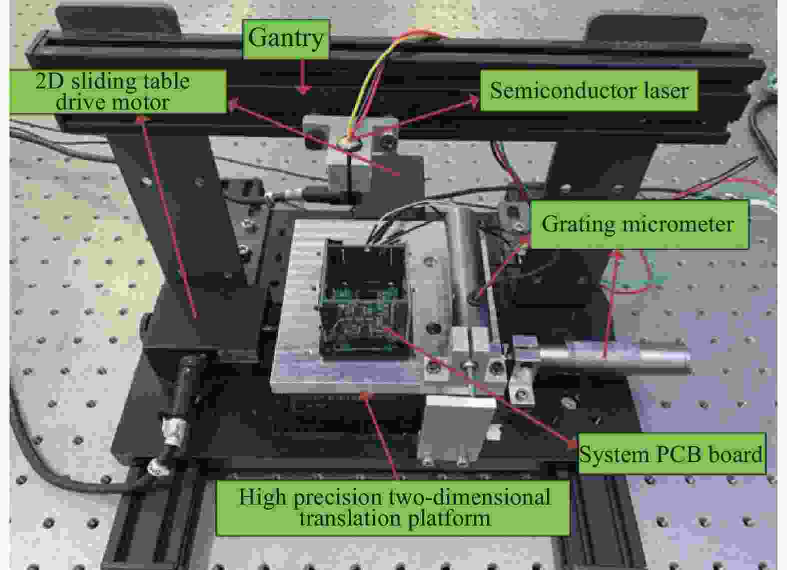
图 5 两PSD标定实验
Figure 5. Two PSD calibration experiments
将采集得到的10组实验数据进行线性拟合,得到图6中方程。可见PSD1、PSD2上斜率均值分别为$ {\overline {{k}} _1} $=−0.00606、$ \overline {{{{k}}_{\text{2}}}} $=−0.01806,即∠θ = arctan$ {\overline {{k}} _2} $−arctan$ \overline {{{{k}}_{\text{1}}}} $ = −0.012 rad,可得旋转矩阵${R}_1=\left(\begin{array}{cc}1 & -2.094\;4 \\2.094\;4 & 1\end{array}\right)$,将PSD2内点坐标与旋转矩阵相乘,各点坐标对应做差取平均得$ \Delta x $=0.009 mm,$\Delta {{y}}$=−0.011 mm,平移矩阵$ {R}_{2}=(0.009 -0.011) $。将补偿矩阵代入PSD2的坐标数据,与PSD1点坐标对应做差得到误差均方根为$\overline {{\Delta x} '}$=0.0005 mm,$\overline {{\Delta {{y}}} ' }$=0.001 mm。
通过对两PSD的标定补偿,大大减小了焊装误差对传感器的影响,为后续的角度结算进行了数据的预处理,提高了坐标值的可信度。

图 6 两PSD标定点位置图
Figure 6. Two PSD calibration point positions
-
传感器用两片PSD输出的二维位置坐标信息来解算三轴角度信息,PSD的输出位置坐标值因信号处理电路以及PSD自身的噪声原因影响,输出的模拟量经过AD采集后输入到MCU时是不稳定的持续抖动值,如图7所示,这时解算的三轴角度信息会成倍地放大该噪声,导致角度的测量值会大范围地进行跳变,因此需对PSD输出值进行滤波处理。测角传感器内部空间较为紧张,模拟滤波器占用较大的硬件空间,所以选用数字滤波器进行数据的处理。常用于处理抖动信号的数字滤波器有卡尔曼滤波器(Kalman Filter, KF)、有限脉冲响应滤波器( Finite Impulse Response,FIR)和无限长脉冲响应滤波器(Infinite Impulse Response, IIR)。
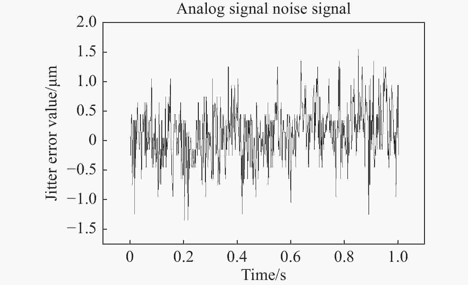
图 7 提取的模拟信号噪声信号
Figure 7. Extracted analog signal noise signal
卡尔曼滤波器的本质是最优估计线性滤波器,它利用数学模型中的输入测量值,通过时间递归系统估计当前状态,主要针对拥有一定惯性保持的线性系统[9]。在三维角度测量传感器中,实时更新的测量值处于非线性的持续改变量,测量的数据有很多不可预测的变化与干扰,很难使用预测性滤波抑制噪声,因此卡尔曼滤波器并不适用于该系统。
IIR滤波器也称为递归滤波器,输出既依赖于输入,也依赖于之前的输出,具有非线性的相位响应,可能表现为不稳定状态,对于测量传感器而言存在不稳定因素会直接影响测量的可靠性与准确性。
FIR滤波器也称为非递归滤波器,输出仅依赖于输入,FIR滤波器拥有更高的鲁棒性,在语音分析、信号跟踪、空间波束形成(空间滤波)等领域广泛应用[10-12]。但在使用FIR滤波器的情况下,时域上的线性相位偏差必须要考虑,也就是滤波器的时滞。
FIR滤波器是一个离散时间系统,其传递函数可表示为:
$$ {H}({{\textit{z}}})={\displaystyle \sum _{{i}={0}}^{{M}}{{a}}_{{i}}{{{\textit{z}}}}^{-1}}\left/\left(1+{\displaystyle \sum _{{i}={1}}^{{M}}{{b}}_{{i}}{{{\textit{z}}}}^{-1}}\right) \right.$$ (12) 式中:M为FIR滤波器的阶数。数字滤波器的函数是无极点的,当bi均为零时,单位脉冲相应时间是有限长度的,这便是有限脉冲响应滤波器的数字表达式。某一时间点的响应为每一个输入在这一刻上的响应的叠加,即为离散时间系统的卷积和:
$$ y(n) = \sum\limits_{i = 0}^M {{a_i} \times h(n - i)} $$ (13) 在采集数据通过FIR滤波器后,输出的数据Qout的表达式为:
$$ {{{Q}}_{{{{\rm{out}}}}}} = \sum\limits_{{{n}} = 1}^{{{M}} + {{1}}} {{{{Q(n)} \times H(n)}}} $$ (14) 式中:Q(n)为采集数据。滤波器的相位时延tm:
$$ {{t}}_{{{\rm{m}}}}=-({M}-1)/2{{F}}_{{{\rm{s}}}} $$ (15) 式中:Fs为采样频率。
设计进行仿真实验,建立频率为1 kHz的正弦波信号P(t)。将实际光斑稳定不动打在PSD靶面上时,采集的坐标位置信号减去均值,提取出真实的在X轴附近跳动的噪声信号f(t)。将两信号叠加生成模拟测量时的输出信号曲线S(t),通过FIR滤波函数进行滤波生成信号曲线S′(t),而为了获得较高的精度,FIR滤波器的阶数取34,为更好地观察噪声,将正弦信号的幅值定为0.010,如图8所示。

图 8 (a) 噪声拟合曲线;(b) 经34阶FIR滤波器滤波后曲线
Figure 8. (a) Noise fitting curve; (b) Curve after filtering with a 34th order FIR filter
由图8(b)可以看出,在滤除噪声的同时出现了相位滞后。34阶FIR滤波效果显著,在实际工程应用上,MCU的运算时间也会影响传感器的带通,不同的处理芯片的运算主频不同,而为了实现三轴信息的高速测量,需要对实际运算MCU及处理电路进行量化的实验验证。
实验分为两个部分依次进行:
1) 测试FIR滤波器在使用系统中频率响应特性;
2) 测试FIR滤波器在传感器上的应用。
使用单片机DAC功能输出频率分别为1.00 Hz、10.00 Hz、100.00 Hz、1.00 kHz的正弦波,将正弦波接入到AD7606的通道内进行采集,将采集后的信号输入到设计好的34阶FIR滤波器中处理,将处理后的信号通过DAC通道2进行输出。将示波器的两个表笔同时连接DAC1和DAC2,查看输入与滤波后输出的波形,如图9所示,蓝色曲线为生成正弦波信号产生的波形,黄色曲线为经过FIR滤波器后生成的信号波形。

图 9 输入信号频率为(a) 1.00 Hz、(b) 10.00 Hz、(c) 100.00 Hz、(d) 1.00 kHz的曲线图
Figure 9. Curve plot of input signal frequency at (a) 1.00 Hz, (b) 10.00 Hz, (c) 100.00 Hz and (d) 1.00 kHz
大周期的信号滤波后的数据在时域上的相位延迟约为525 μs,但输出幅值与频率并无变化,实测FIR滤波器在单片机内运行的时间为5 μs,包含在产生的相位延迟内。在实际工程应用上,光电伺服转台的伺服周期都在0.1~0.01 s范围内,5%以下的延迟在可接受的范围内。输入信号频率在1.00 kHz时产生极大的失真,已看不出原有的正弦波,说明滤波器已经对该频率响应了。为了找到滤波器在该程序中的带宽特性[13-15],寻找滤波器的频率响应极限,如图10所示。

图 10 输入信号频率为 (a) 184 Hz和(b) 1.31 kHz的曲线图
Figure 10. Curve plot of input signal frequency at (a) 184 Hz and (b) 1.31 kHz
由图10可知,在输入信号频率为184 Hz时,波形产生较为明显的失真,滤波器开始响应该频率以上的信号。在输入信号频率为1.31 kHz时,幅值降低为原幅值(−3 dB),滤波器的响应带宽为1.31 kHz,对于所有超出带宽频率的信号会被很大程度地衰减,对于电压模拟信号造成的高频信号进行了有效的消除。
将滤波器写入MCU程序内,使用传感器测试静态时单通道的采集数据与滤波后的数据,如图11所示,数据的标准差从0.000354°变为0.000071°,降低了20%,大大提高了测量的稳定性,为后续计算三轴角度信息提供了稳定输入信号。

图 11 采集数据与滤波后的数据对比图
Figure 11. Comparison diagram between collected data and filtered data
将六路信号输入到FIR滤波器中,并同时使用滤波前后的两组数据分别进行角度解算,采集滤波前与滤波后的角度数据,如图12所示。

图 12 (a) 方位轴角度测量值、(b) 俯仰轴角度测量值、(c) 横滚轴角度测量值滤波前后对比图
Figure 12. Comparison diagrams of (a) yaw angle measurement values, (b) pitch angle measurement values, (c) roll angle measurement values before and after filtering
测量单片机程序运行周期为870 μs,即测角传感器的带宽为1.15 kHz,实现高速测量。方位角度数据的标准差从0.000251°变为0.000127°,俯仰角度数据的标准差从0.000367°变为0.000211°,横滚角度数据的标准差从0.00216°变为0.0013°。由此可见,角度测量的稳定性均提高了一倍,滤除了不稳定噪声对传感器测角的影响。
-
为了验证三轴测角传感器的精度,利用H850-pi六轴六足纳米位移台实现精准角度发生,性能如表2所示。搭建角度标定平台,使用自准直仪及工装加工手段将位移台的坐标系与三轴角度传感器坐标轴平行,通过微调升降台对正坐标原点,角度测量实验系统如图13所示。
表 2 六轴六足纳米位移台性能指标
Table 2. Performance indicators of six axis hexapod nano displacement table
Performance Typical value/μm Performance Typical value/μrad X, Y accuracy ±0.6 $ {\theta } $X, $ {\theta } $Y accuracy ±3 Z accuracy ±0.2 $ {\theta } $Z accuracy ±9 X, Y resolution ratio 0.3 $ {\theta } $X, $ {\theta } $Y resolution ratio 3 Z resolution ratio 0.2 $ {\theta } $Z resolution ratio 5 
图 13 角度测量实验系统
Figure 13. Angle measurement experimental system
分别调整纳米位移台转动角度,记录当前转动角度值,同时读取传感器解算角度数据,在±2°的范围内间隔0.5°进行测量。分别在没有添加FIR滤波器与添加FIR滤波器的情况下分组实验。测量实验分两步进行:
1)在其他两轴固定不动时,改变当前测量轴系的旋转角度进行测量,共27组数据;
2)进行三轴组合测量,在测量范围内选取典型测量点(方位角=俯仰角=横滚角)进行测量,共18组数据。
传感器解算角度与位移台发生角度对比得到的测角误差如表3所示,误差值为各测量角度误差的均方根。后续均进行三次实验后取均值,以保证实验结果的的普遍性。
表 3 测角误差
Table 3. Angle measurement error
Yaw angle measurement error $ {\sigma _{{x}}} $/(°) Pitch angle measurement error $ {\sigma _{{y}}} $/(°) Roll angle measurement error $ {\sigma _{{z}}} $/(°) No filtering:
Yaw angle0.005 0.012 0.021 No filtering:
Pitch angle0.005 0.011 0.020 No filtering:
Roll angle0.007 0.015 0.026 No filtering:
Combined
measurement0.013 0.020 0.039 Filtering:
Yaw angle0.003 0.007 0.013 Filtering:
Pitch angle0.002 0.007 0.015 Filtering:
Roll angle0.004 0.007 0.017 Filtering:
Combined measurement0.006 0.009 0.021 由此可见,在FIR滤波器的效果下将误差减少到原来的50%左右,滤波器效果显著,大大提高了传感器的精度。在FIR滤波器的作用下,所设计传感器的方位角测量误差为0.006°,俯仰角测量误差为0.009°,横滚角测量误差为0.021°,且三轴同时测量的串扰现象较小。
在实际工程应用条件下,三轴角度测量应对平移不敏感。设光楔中心与准直镜头中心对准时为零点,此时测量的角度值为零点数据,测量(方位角/(°),俯仰角/(°),横滚角/(°))分别等于(0, 0, 0)、(1, 1, 1)、(2, 2, 2)、(−1, −1, −1)、(−2, −2, −2)时,控制纳米位移台相对自准直测量单元在上下、左右、前后六个方向分别平移2 mm,比较测量值与零点数据,得到如表4所示的误差数据。
表 4 平移对角度测量影响实验结果
Table 4. Experimental results of the effect of translation on angle measurement
Yaw angle translation influence ${\sigma }_{{x} }^{\prime}$/(°) Pitch angle translation influence ${\sigma }_{{y} }^{\prime}$/(°) Roll angle translation influence ${\sigma }_{{z} }^{\prime}$/(°) Move forward
2 mm0.001 0.001 0.007 Move back
2 mm0.004 0.001 0.003 Move up
2 mm0.003 0.001 0.004 Move down
2 mm0.002 0.001 0.005 Move left
2 mm0.002 0.001 0.004 Move right
2 mm0.001 0.002 0.005 由表4可以看出,所设计传感器中平移对角度测量影响很小,平移对方位角的影响的平均值$ \overline{{\sigma }_{{x}}^{\prime}} $=0.002°,俯仰角的影响的平均值$ \overline{{\sigma }_{{y}}^{\prime}} $=0.001°,横滚角的影响的平均值$ \overline{{\sigma }_{{y}}^{\prime}} $=0.005°。
-
文中提出一种基于双PSD的三轴角度测量传感器,并对其测量过程中产生影响的误差源进行了分析以及补偿。对两片PSD的相对位置进行了标定,利用旋转矩阵和平移矩阵消除了因焊装引起的误差。选定使用FIR滤波器进行数据处理,分析了选用34阶FIR滤波器的相频响应特性,测量出实际运用时的带宽。依据项目实际要求设计处理电路及器件选型,在选用器件的基础上进行实验验证。结果表明,FIR滤波器将角度测量误差减小了40%,基于双PSD的三维测角传感器在±2°的测量范围内,方位角的测量精度达到0.006°,俯仰角的测量精度达到0.009°,横滚角的测量精度达到0.021°,传感器响应频率可以达到1.15 kHz。相对其他常规三轴测角传感器而言,该装置拥有体积小、精度高、测量范围大、带宽高、非接触、轴向方向平移不敏感等优势,为机载跟瞄转台上光电载荷与外框架基座间的角度检测提供了一种可靠的三轴测角方法。
Accuracy analysis of a three-dimensional angle measurement sensor based on dual PSDs
-
摘要: 在机载光电转台、多自由度摇摆台等系统中,对于一些运动体与基座间没有确定的回转轴的柔性支撑、并联支撑平台,需要考虑非接触三轴角度测量方法,目前大部分的光电非接触三轴角度测量方案系统复杂,占用空间大,无法适用于如机载、星载等载荷对体积、质量敏感的场景。为此,文中提出了基于双位置敏感探测器(PSD)的非接触三轴角度测量方案,使用准直镜头汇聚、双面反射光楔反射,将光源在两片PSD上汇聚成像,利用PSD上的光斑位置坐标反解出三轴角度。描述了其工作原理以及传感器构成,分析了因两片PSD的相对位置偏移产生的误差,提出了对应补偿方法以减少焊装产生的PSD位置偏移对测量精度的影响。主要对采集的PSD模拟信号值的抖动噪声进行FIR滤波处理,分析了滤波器的相频响应特性,并在MCU中测量相位滞后时间以及滤波器的响应带宽,验证了该数字滤波器在系统内拥有较好的实时传输特性。自准直测量单元总质量为230 g,尺寸为50 mm×50 mm×50 mm。实验结果表明,34阶FIR滤波器将角度测量的误差减小至60%,在±2°测量范围内单轴测量时,方位角、俯仰角、横滚角的误差均方根分别为0.003°、0.007°、0.017°,组合测量时分别为0.006°、0.009°、0.021°,文中所提出的三维测角传感器精度较高,满足机载等场景的使用要求。Abstract:
Objective In systems such as airborne photoelectric turntables and multi degree of freedom swing tables, three-dimensional angle measurement is often required. The methods of angle measurement are divided into contact measurement and non-contact measurement, and different measurement methods need to be selected based on actual application scenarios. For some flexible supports, parallel support platforms, and uncertain rotation axes between the moving object and the base, non-contact measurement methods need to be considered. At present, the common non-contact three-axis angle measurement schemes are complex and occupy a large space, which cannot meet the volume and weight requirements of airborne and spaceborne payload. Therefore, it is necessary to develop a non-contact three-axis angle measurement method with a simple structure and small footprint to meet the needs of different usage environments. Therefore, a non-contact three-dimensional angle measurement system based on two position sensitive detectors (PSD) has been proposed. Methods A three-axis angle measurement system based on dual PSD has been established. The system mainly consists of two parts of an autocollimation measurement unit and a double-sided reflection wedge (Fig.2). The autocollimation measurement unit includes a light source, PSD1, PSD2, autocollimation lens, and subsequent processing circuits. The light beam emitted by the light source converges into parallel light through a collimating lens. And PSD1 and PSD2 receive the light spot converged by the reflected beam and perform signal processing calculations through a processing circuit. The double-sided reflective wedge is designed with a semi-reflective and semi-transparent front surface and a fully reflective rear surface. Its function is to disperse the incident collimated parallel light into two beams and reflect them back into the self-collimating lens, which converges onto the target surfaces of two PSDs to form a light spot. According to the principle of angle measurement, the calibration method of two PSDs is designed to compensate for welding errors, and the FIR filtering algorithm is used to filter the simulated collected signal to improve accuracy. Results and Discussions A three-axis angle measurement system based on dual PSD has been designed, and a calibration experimental system (Fig.5) has been established to calibrate the relative position relationship between two PSDs. The welding error of the relative positions of the two PSDs is compensated through the rotation matrix and translation matrix, and the compensation result is great. A 34th-order FIR filter was designed and simulated, and the experimental results show that the designed filter has a good filtering effect on the actual collected noise signals. The filter is applied to the actual processing MCU for experiments, and the phase frequency response characteristics of the selected filter are analyzed. The test results show that the response bandwidth of the filter is 1.31 kHz, which can effectively filter out high-frequency noise signals in the analog voltage signal. The angle measurement experimental system (Fig.13) has been established, and the three-axis angle measurement function of the system has been verified. The system also has high accuracy. Conclusions A non-contact three-axis angle measurement system based on dual PSD is designed. This system has advantages such as simple structure, small size, high accuracy, large measurement range, high bandwidth, non-contact, and insensitivity to axial translation. The rotation matrix, translation matrix, and the designed 34th-order FIR filter obtained from calibrating two PSDs are coded and written into the STM32F4 series microcontroller, and the filter delay is approximately 525 μs, which is within an acceptable range. The processing circuit and selected devices designed according to the actual requirements of the project have been experimentally verified. Within a measurement range of ± 2°, the accuracy of yaw angle measurement reaches 0.006°, pitch angle measurement accuracy reaches 0.009°, and roll angle measurement accuracy reaches 0.021°. The overall autocollimation measurement unit weighs 230 g and has a size of 50 mm × 50 mm × 50 mm square box. The response frequency of the measurement system can reach 1.15 kHz. This system can measure the three-axis angle in real-time at high speed with high accuracy and small volume, and is suitable for various engineering applications, providing stable and high-speed three-axis angle measurement solutions for airborne, spaceborne, and other conditions. -
图 8 (a) 噪声拟合曲线;(b) 经34阶FIR滤波器滤波后曲线
Figure 8. (a) Noise fitting curve; (b) Curve after filtering with a 34th order FIR filter
图 9 输入信号频率为(a) 1.00 Hz、(b) 10.00 Hz、(c) 100.00 Hz、(d) 1.00 kHz的曲线图
Figure 9. Curve plot of input signal frequency at (a) 1.00 Hz, (b) 10.00 Hz, (c) 100.00 Hz and (d) 1.00 kHz
图 10 输入信号频率为 (a) 184 Hz和(b) 1.31 kHz的曲线图
Figure 10. Curve plot of input signal frequency at (a) 184 Hz and (b) 1.31 kHz
图 11 采集数据与滤波后的数据对比图
Figure 11. Comparison diagram between collected data and filtered data
图 12 (a) 方位轴角度测量值、(b) 俯仰轴角度测量值、(c) 横滚轴角度测量值滤波前后对比图
Figure 12. Comparison diagrams of (a) yaw angle measurement values, (b) pitch angle measurement values, (c) roll angle measurement values before and after filtering
表 1 各三轴测角方法性能指标
Table 1. Performance indicators of each three-axis angle measurement methods
Specifications Dual autocollimation instrument type MCCR instrument type Three PSD grating type Angle measurement range ±2' ±10° ±360" Yaw angle measurement error 2.2" 394.16 " 0.013" Pitch angle measurement error 2.5" 455.36 " 0.012" Roll angle measurement error 8.7" 319.57" 0.009"  下载: 导出CSV
表 2 六轴六足纳米位移台性能指标
Table 2. Performance indicators of six axis hexapod nano displacement table
Performance Typical value/μm Performance Typical value/μrad X, Y accuracy ±0.6 $ {\theta } $X, $ {\theta } $Y accuracy ±3 Z accuracy ±0.2 $ {\theta } $Z accuracy ±9 X, Y resolution ratio 0.3 $ {\theta } $X, $ {\theta } $Y resolution ratio 3 Z resolution ratio 0.2 $ {\theta } $Z resolution ratio 5
下载: 导出CSV
表 3 测角误差
Table 3. Angle measurement error
Yaw angle measurement error $ {\sigma _{{x}}} $/(°) Pitch angle measurement error $ {\sigma _{{y}}} $/(°) Roll angle measurement error $ {\sigma _{{z}}} $/(°) No filtering:
Yaw angle0.005 0.012 0.021 No filtering:
Pitch angle0.005 0.011 0.020 No filtering:
Roll angle0.007 0.015 0.026 No filtering:
Combined
measurement0.013 0.020 0.039 Filtering:
Yaw angle0.003 0.007 0.013 Filtering:
Pitch angle0.002 0.007 0.015 Filtering:
Roll angle0.004 0.007 0.017 Filtering:
Combined measurement0.006 0.009 0.021
下载: 导出CSV
表 4 平移对角度测量影响实验结果
Table 4. Experimental results of the effect of translation on angle measurement
Yaw angle translation influence ${\sigma }_{{x} }^{\prime}$/(°) Pitch angle translation influence ${\sigma }_{{y} }^{\prime}$/(°) Roll angle translation influence ${\sigma }_{{z} }^{\prime}$/(°) Move forward
2 mm0.001 0.001 0.007 Move back
2 mm0.004 0.001 0.003 Move up
2 mm0.003 0.001 0.004 Move down
2 mm0.002 0.001 0.005 Move left
2 mm0.002 0.001 0.004 Move right
2 mm0.001 0.002 0.005
下载: 导出CSV
-
[1] Li Quanchao. Research on mechanism of aerial high-precision optoelectronic platform based on universal joint[D]. Changchun: Chinese Academy of Sciences (Changchun Institute of Optics, Fine Mechanics and Physics, Chinese Academy of Sciences), 2022. (in Chinese) [2] Sun Guoyan, Gao Limin, Bai Jianming, et al. High accuracy three-dimensional attitude angle measuring device [J]. Optics and Precision Engineering, 2016, 24(5): 963-970. (in Chinese) doi: 10.3788/OPE.20162405.0963 [3] Li R, Zhen Y, Di K, et al. Three-degree-of-freedom autocollimator with large angle-measurement range [J]. Measurement Science and Technology, 2021, 32(11): 115005. doi: 10.1088/1361-6501/ac1236 [4] Ren W, Cui J, Tan J. A three-dimensional small angle measurement system based on autocollimation method [J]. Review of Scientific Instruments, 2022, 93(5): 055102. [5] Tang Jiuyao, Li Jinjun, Sun Xiaobin. Preparation of a pin-cushion two-dimensional position sensitive detector [J]. Acta Optica Sinica, 2005, 25(2): 233-236. (in Chinese) [6] Sang Hongyan. Research on dynamic response characteristic of PSD with pin-cushion type [J]. Transducer and Microsystem Technologies, 2007(181): 34-36. (in Chinese) [7] Huang Meizhen, Tang Jiuyao, Chen Yuqing. Position sensitive detector based on the lateral photoelectric effect [J]. Electronics Optics & Control, 2000(2): 34-38. (in Chinese) [8] Zheng Jun, Li Wenqing. Calibration of 3-D measurement system based on a double position sensitive detectors [J]. J Tsinghua Univ (Sci & Technol), 2018, 58(4): 411-416. (in Chinese) [9] Khodarahmi M, Maihami V. A review on Kalman filter models [J]. Archives of Computational Methods in Engineering, 2023, 30(1): 727-747. doi: 10.1007/s11831-022-09815-7 [10] de Cacqueray-Valmenier M, Coskun A, Kale I. The use of almost linear phase IIR filters in DFT modulated filter banks for communication systems [C]//2016 IEEE 17th International Workshop on Signal Processing Advances in Wireless Communications (SPAWC). IEEE, 2016: 1-4. [11] Stavrou V N, Tsoulos I G, Mastorakis N E. Transformations for FIR and IIR filters’ design [J]. Symmetry, 2021, 13(4): 533. doi: 10.3390/sym13040533 [12] Pak J M. Gaussian sum FIR filtering for 2D target tracking [J]. International Journal of Control, Automation and Systems, 2020, 18: 643-649. doi: 10.1007/s12555-018-0938-4 [13] Lowenborg P, Johansson H. Minimax design of adjustable-bandwidth linear-phase FIR filters [J]. IEEE Transactions on Circuits and Systems I: Regular Papers, 2006, 53(2): 431-439. doi: 10.1109/TCSI.2005.857549 [14] Haridas N, Elias E. Low-complexity technique to get arbitrary variation in the bandwidth of a digital FIR filter [J]. IET Signal Processing, 2017, 11(4): 372-377. doi: 10.1049/iet-spr.2016.0055 [15] Wang Yufei, Zheng Jiaxing, Dai Dongkai, et al. A non-delay measurement method for RLG based on the combination of FIR filtering and dither stripping[J]. Infrared and Laser Engineering, 2023, 52(11): 20230171. (in Chinese) -

 点击查看大图

计量
- 文章访问数: 128
- HTML全文浏览量: 28
- PDF下载量: 31
- 被引次数: 0

