


 下载:
下载:


-
中红外波段(2.5~25 μm)在光谱学和成像领域具有重要的应用价值。中红外光谱是大分子结构物质的振转光谱吸收和辐射的主要频谱段,被称为化学指纹谱区,在物质成分分析中具有重要应用[1]。此外,该波段是常温到较高温物体热辐射的主要波段,且包含了3~5 μm和8~14 μm这两个大气透明窗口。因此,中红外光谱在分子检测[2]、医学诊断[3]、遥感与目标识别[4]和大气通信[5]等领域具有丰富的应用,近年来吸引人们开展广泛研究。尽管中红外光谱和成像技术具有众多优点和巨大的应用潜力,但工作于该波段探测器的发展仍落后于各种应用需求。与可见光或近红外探测器相比,传统的中红外半导体探测器在探测灵敏度、噪声水平、响应时间和成本等方面具有明显劣势。尽管基于窄带隙材料(如碲镉汞(MCT)和砷化铟(InAs))的探测器以及超导探测技术已经在中红外波段达到较高灵敏度和量子效率,但其极度依赖于深度冷却来减少暗噪声,这给众多实际应用带来了额外的负担。
频谱迁移技术是一种有效的补充方案,其思想是将中红外信号光通过非线性频率过程上转换为可见光/近红外光,然后使用基于宽带隙材料(例如硅)的高性能探测器进行检测[6-7]。这种方案具有响应速度快、可室温操作等优点,并已经在通讯波段的各类应用场景中得到了验证与发展[8-9]。近年来,上转换探测研究已开始扩展到中红外波段,在单点和图像探测领域都取得了一定的进展[10-11]。其中,基于波导的上转换探测方案由于系统内部的高功率密度获得了较高的转换效率,但由于波导结构对空间模式的限制,一般只能应用于点探测场景中[12]。而在需要面阵探测的成像场景中,体块晶体得益于足够大的通光孔径,因此成为上转换成像应用的首选。周期性极化晶体在波长选择范围、转换效率等方面均优于角度相位匹配晶体,尤其是经过啁啾极化的晶体,由于具有较大的相位匹配带宽,在成像接受带宽、视场等方面都具有明显优势[13-15]。
文中基于啁啾极化晶体,对中红外图像上转换技术进行了系统研究。由于上转换探测的一大优势是可以对成像过程中各性能参数进行灵活调控,如可对带宽、视场、量子效率等参数进行一定调整以满足不同应用场景,因此进行系统的成像理论研究对相关实验的设计与实现尤为重要。以往的工作主要着眼于线性成像定量与非线性转换定性相结合的方法[16-18]进行上转换成像理论研究,没有考虑信号光在晶体中的非线性过程对传播的影响,因此与弱信号光条件下的上转换成像结果存在一定偏差。文中通过直接离散耦合波方程,充分考虑了非线性过程对光传播的影响,根据基本的成像原理,给出了上转换成像过程的一个简单物理模型,将理论分析与数值计算相结合可以得到更为直观、准确的成像结果。此外,文中报道了利用啁啾极化晶体在实验上实现接受带宽为597 nm、视场角为16.59°的中红外上转换成像,并且在输入红外信号为单光子量级的条件下实现了高灵敏度、低噪声的目标识别,验证了啁啾极化晶体在该技术中的优势。借助这项技术,文中还演示了相干光照明条件下的光学边缘增强与热辐射非相干光目标的温度识别两种具体应用。团队的工作为基于啁啾极化晶体的相干/非相干辐射光照条件下的上转换成像提供了理论推导,并展示了不同照明条件下上转换成像的具体应用。
-
上转换成像是基于非线性晶体中的和频过程(Sum-Frequency Generation, SFG)的一种技术,其中频率为$ {\omega _s} $的中红外信号光通过频率为$ {\omega _p} $的泵浦光上转换为$ {\omega _{S F}} $的和频光。该过程满足能量守恒定律,即$ \hbar {\omega _s} + \hbar {\omega _p} = \hbar {\omega _{S F}} $,其中$ \hbar $是普朗克常数。为了利用最高的晶体非线性系数,准相位匹配(Quasi-Phase Match, QPM)技术被提出并广泛应用于补偿三束光在晶体内的相位失配,并且晶体的极化周期引入的空间矢量$ {\stackrel{\rightharpoonup }{k}}_{\varLambda } $被设计为$ \Delta \stackrel{\rightharpoonup }{k}={\stackrel{\rightharpoonup }{k}}_{s}+{\stackrel{\rightharpoonup }{k}}_{p}+{\stackrel{\rightharpoonup }{k}}_{\varLambda }-{\stackrel{\rightharpoonup }{k}}_{S F}=0 $,满足动量守恒条件。在大多数非线性过程的应用场景中,一般利用共线匹配以实现更大长度的光束交叠区域,从而获得更高的转换效率。然而,对于图像上转换场景,图像不同部分在晶体内的传播角度不同,因此非共线相位匹配将直接影响上转换成像的视场、效率、带宽等重要参数。在传播方向与垂直传播方向上分解空间矢量,如图1所示,可以将相位匹配条件用公式(1)描述:
$$ \left\{ \begin{array}{l} {k_{S F}}\cos \varphi = {k_s}\cos \theta + {k_p} + {k_{\rm{\varLambda}} } \\ {k_{S F}}\sin \varphi = {k_s}\sin \theta \end{array} \right. $$ (1) 式中:$ {k_s},{k_p},{k_{S F}},{k_\varLambda } $分别代表中红外信号光、泵浦光、和频光和晶体极化引入的空间矢量大小,可以表示为$ {k_i} = 2\pi {n_i}/{\varLambda _i}(i = s,p,S F) $,$ {n_i} $和$ {\varLambda _i} $分别为三束光在晶体中的折射率(一般与波长、晶体温度相干,可利用smellier公式求解)和在真空中的波长,$ {k_\varLambda } = 2\pi m/\varLambda $,$ m $为相位匹配阶数,$ \varLambda $为晶体的极化周期长度;$ \theta $和$ \varphi $分别表示信号光、和频光与传播方向的夹角。
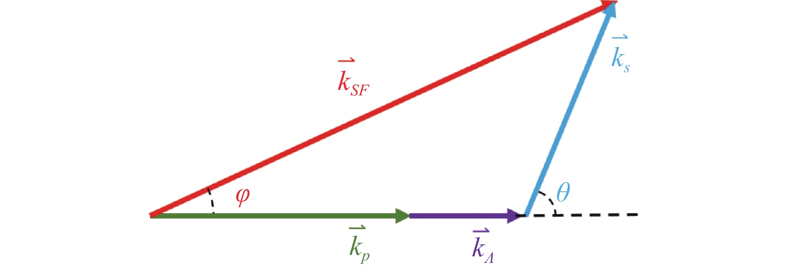
图 1 非共线相位匹配示意图
Figure 1. Schematic diagram of non-collinear phase matching process
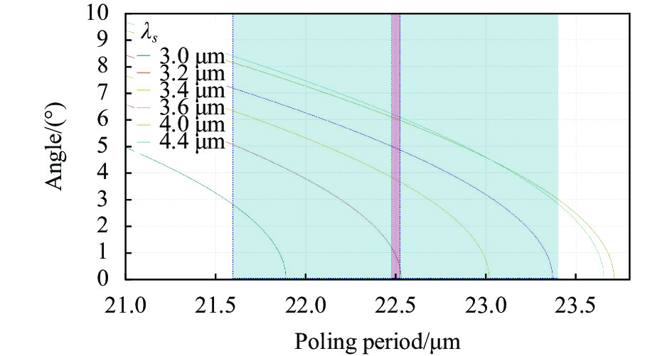
在实际转换过程中,泵浦光的波长和传输方向通常是确定的,结合能量守恒方程,利用公式(1)可以建立起晶体极化引入的格矢量大小$ {k_\varLambda } $与信号光波长$ {\varLambda _s} $、入射角度$ \theta $的二元函数关系。因此在上转换成像过程中,转换带宽和视场大小是相互关联的两个参量,即一般较大的转换带宽对应着较大的转换视场。对于确定的信号光波长,如图2所示,一般而言随着入射角度$ \theta $增大,满足相位匹配条件的格矢量大小$ {k_\varLambda } $越大,即需要更小的极化周期。
单周期极化铌酸锂(PPLN)晶体常用于红外上转换技术中,由于具有确定且唯一的极化周期(即唯一确定的极化空间格矢),其转换带宽和视场角度都相应较小,这在一定程度上限制了大带宽、大视场角的上转换成像技术发展。解决这些问题的可行解决方案有:在晶体中制造温度梯度,或者利用具有宽谱泵浦光进行泵浦[19-20],即在公式(1)中增加一个可调谐的自变量,从而扩大满足相位匹配条件的波长和角度范围。然而,这类方案不仅增加了系统的复杂程度,对泵浦光源也提出了更高的要求,使其难以满足各种应用场景。另一种方案是采用在极化过程中引入不同极化周期的啁啾极化晶体,相当于$ {k_\varLambda } $具有一系列不同的取值,从而极大地增加了晶体的转换接受带宽和成像视场。 如图2所示,红色阴影区域表示单周期极化晶体的匹配范围,蓝色阴影区域代表啁啾极化晶体的匹配范围。 因此,啁啾极化晶体在接受带宽和视场角度的表现上优于单周期极化晶体。

图 2 铌酸锂晶体处于30 ℃,在1080 nm泵浦光作用下,不同极化周期对应的相位匹配波长和角度的关系图
Figure 2. The relationship between phase matching wavelength and half-angle of the field of view with different polarization periods of lithium niobite (LN) crystal at 30 ℃ under the action of 1080 nm pump beam
在成像应用中,特别是当探测目标为物体热辐射发出的完全非相干光时,信号光中包含了不同的波长和空间角度分量。这种应用场景需要不同的极化周期来满足相位匹配条件,以实现大视场和大带宽的图像转换,因此啁啾极化晶体在中红外上转换成像领域具有显著优势。
-
耦合波方程描述了三束光的电矢量在晶体内传播过程中的相互作用,可以写为[21-22]:
$$ {\nabla }^{2}\stackrel{\rightharpoonup }{E}\left({\omega }_{n},z\right)+{\mu }_{0}{\omega }_{n}^{2}\stackrel{\rightharpoonup }{\varepsilon }\left({\omega }_{n},z\right)\cdot\stackrel{\rightharpoonup }{E}\left({\omega }_{n},z\right)=-{\mu }_{0}{\omega }_{n}^{2}\stackrel{\rightharpoonup }{{P}_{NL}}\left({\omega }_{n},z\right) $$ (2) 对于二阶非线性和频过程,在慢变振幅近似的条件下,和频光束的电场复振幅沿传播方向(假设为z轴)变化的标量方程可以表达为:
$$ i2{k_{S F}}\frac{{\partial {E_{S F}}}}{{\partial z}} + \nabla _ \bot ^2{E_{S F}} = - \frac{{\omega _{S F}^2{d_{eff}}}}{{{\varepsilon _0}{c^2}}}{E_s}{E_p}{{\rm{e}}^{i\Delta kz}} $$ (3) 式中:$ \Delta k = {k_{S F}} - {k_{sz}} - {k_{pz}} + 2\pi /\varLambda $为和频过程中传播方向上的相位失配;$ {k_{sz}},{k_{pz}} $分别代表信号光和泵浦光波矢在z方向上的投影大小;$ {\varepsilon _0} $和$ c $分别代表真空中的介电常数和光速;$ {d_{eff}} $为有效非线性系数;$ {E_i}\left( i = s,p,SF \right) $分别代表信号光、泵浦光和和频光的标量复振幅;$ \nabla _ \bot ^2{\text{ = }}\dfrac{{{\partial ^2}}}{{\partial {x^2}}}{\text{ + }}\dfrac{{{\partial ^2}}}{{\partial {y^2}}} $代表垂直传播方向的拉普拉斯算子。
信号光、泵浦光以及和频光在入射晶体前的复振幅分布信息是容易确定的,即z=0位置$ {E_i}\left( {i = s,p,S F} \right) $分布确定。根据此条件,可以利用向前差分方法离散和频光的耦合波方程:
$$ {E_{S F}}\left( {x,y,z + {\mathrm{d}}z} \right) = {E_{S F}}\left( {x,y,z} \right) + \frac{i}{{2{k_{S F}}}}\left[ {\nabla _ \bot ^2{E_{S F}}\left( {x,y,z} \right) + \frac{{\omega _{S F}^2{d_{eff}}}}{{{\varepsilon _0}{c^2}}}{E_s}\left( {x,y,z} \right){E_p}\left( {x,y,z} \right){{\mathrm{e}}^{i\Delta kz}}} \right]{\mathrm{d}}z $$ (4) 通过这种离散方法,在初始条件已知的情况下,可以对晶体内任意位置处的三束光的复振幅和强度分布进行求解。相比于传统的分步傅里叶方法,由于同时考虑了传播和非线性演化,这种计算方法将带来更高的计算精度。
对于非相干照明情况,可以对在z=0位置处的$ {E_s} $添加随机相位并多次求解取平均值、改变传播方向(即改变$ \Delta k $),从而消除了信号光的空间相干性和时间相干性。以此为基础模拟非相干照明光场,可以对图像转换进行较为准确的数值计算。
-
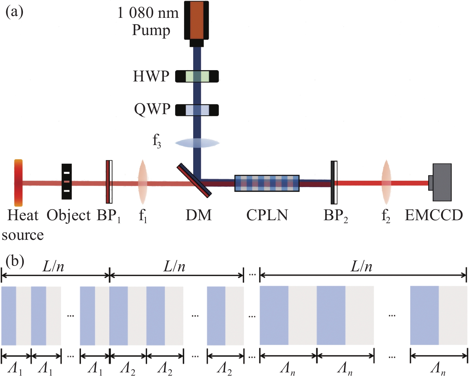
实验装置如图3所示,通过加热烙铁产生非相干的中红外热辐射光源。物体被热光源照明后,利用带通滤波片来滤除辐射源中的可见光成分。强的1080 nm泵浦光通过二向色镜(DM)与信号光合束后一起射入晶体。通过一个4f系统,将目标的上转换结果成像在EMCCD上。两透镜焦点位置与晶体中心重合,以保证信号光能够被充分转换。实验中使用了极化周期间隔为0.01 μm、周期范围为21.6~23.4 μm的啁啾极化铌酸锂(CPLN)晶体,晶体的长度为40 mm,横截面尺寸为2 mm×3 mm。采用自制的温度控制器对CPLN晶体进行控温,其温度涨落为±0.002 ℃。图中,BP1为中心波长为 4000 nm、带宽为 2000 nm的带通滤波片;BP2为中心波长为800 nm、带宽为40 nm的带通滤波片;f1、f2、f3为透镜;DM为二向色镜;HWP为半波片;QWP为四分之一波片。
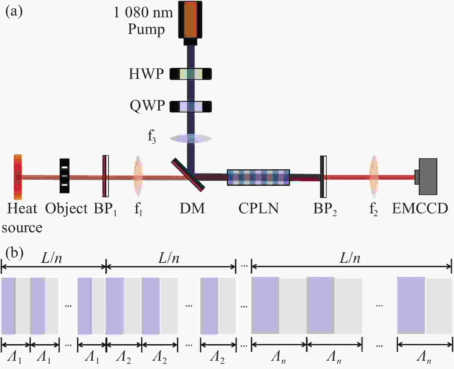
图 3 实验装置示意图。(a)实验光路图;(b)啁啾极化晶体结构示意图
Figure 3. Schematic diagram of the experimental setup. (a) Experimental configuration diagram; (b) Schematic diagram of chirp polarization crystal structure
-
对于被动探测方式,目标一般具有广谱特性,因此要求探测器具有更宽的接受带宽以实现更高效率和效果的识别。
通过求解非线性耦合波方程,可以得到上转换的效率正比于$\sin {{\rm{c}}^2}\left( {\dfrac{{\Delta k \cdot {L_{eff}}}}{2}} \right)$。啁啾极化晶体引入了更多的极化周期$ \varLambda $,但减小了晶体的有效长度$ {L_{eff}} $,因此啁啾极化晶体相比于单周期极化晶体在接受带宽上具有显著优势。
热源辐射的中红外信号光在1080 nm强泵浦光的作用下,利用啁啾极化晶体通过非线性和频过程上转换为可见光,再利用成熟的光谱仪测量其上转换后的频谱。结合能量守恒定律,可以求得上转换过程在对应中红外波段的接受光谱,如图4所示。

图 4 直接探测上转换光所得光谱图
Figure 4. Directly detecting the spectrum obtained from up-conversion beam
由图4可得和频光的半高全宽(Full-width of half-max, FWHM)为38 nm,波长范围为788~826 nm;对应中红外的接受范围为2 915~3 512 nm,其半高全宽为597 nm。由于DM在大于3400 nm的波长上透过率较低,实际的转换带宽要大于直接测量结果,这一结果与图2给出的数值计算结果相吻合。相比之下,单周期极化晶体的波长接受带宽仅为纳米量级[23-24],因此啁啾极化晶体拓宽系统的接受带宽达到2个数量级,对探测光谱目标十分有益。
-
上转换成像的视场(Field of View, FOV)主要受到孔径光阑和非线性晶体角度接受范围的限制。一般而言,对于确定的信号光波长,具有大入射角的信号光需要较小的极化周期(即较大的空间格矢)来满足相位匹配条件(见图2)。啁啾极化晶体包含了从小到大的不同极化周期,因此在大视场上转换成像上具有明显优势。
用中红外信号光大范围照明刻度板,通过上转换后在EMCCD上读取可以被转换的信号光空间范围,可以计算得到上转换的视场范围。经过上转换后的图像如图5所示。
刻度板置于透镜f1的焦平面处,与透镜的距离为125 mm。上转换成像结果中最大的一维尺寸为3.62 cm,对应125 mm传播距离,其视场全角为16.59°,这一结果略小于图2中的数值计算结果。

图 5 中红外光照明刻度板成像结果
Figure 5. Imaging results of mid-infrared illuminated scale plate
需要注意的是,实现大视场上转换成像不仅要保证晶体的极化周期满足大角度入射光的相位匹配条件,同时也要避免晶体成为成像系统的孔径光阑。能够通过晶体的信号光的最大入射角度近似等于晶体对角线连线与传播方向的夹角,目前极化工艺很难做到大厚度的均匀极化,因此减小晶体长度是提升视场角度的有效方法。
-
相比于直接测量方法,上转换方法在和频过程中会额外引入一定的噪声,但绝大多数噪声可以通过滤波片等滤除,因此上转换方法的主要噪声来源仍为探测器引入的噪声。上转换方法可以选取宽带隙的半导体材料,相比于直接测量所使用的窄带隙材料,这类材料制作的探测器对热噪声不敏感,因此不需要深制冷;硅探测器在常温下噪声等效功率比常温条件下的InAs中红外探测器低五六个数量级、比深制冷条件下的低一二个数量级;硅光探测器结电容等电学参数也要优于中红外半导体器件,因此具有更高的响应频率。采用上转换测量方法,将非常有助于提高中红外成像的信噪比。如图6所示,弱信号光条件下,相同功率的中红外光通过碲镉汞热像仪直接成像的背景充斥着白噪声,难以辨识目标轮廓信息,而上转换方法得到的图样背景干净、信噪比高。
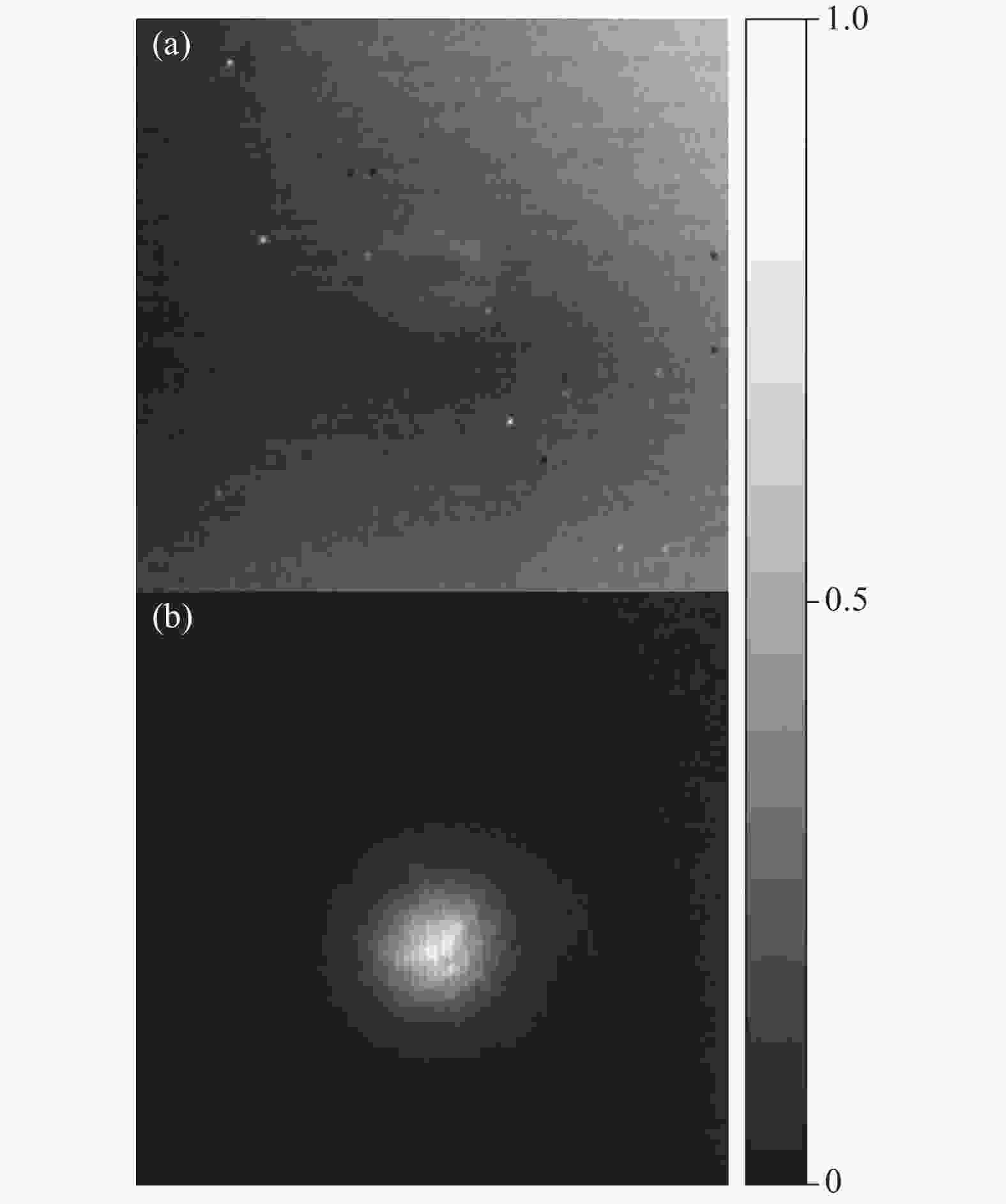
图 6 中红外光直接探测与上转换探测结果对比。(a)碲镉汞热像仪成像结果;(b)上转换后硅基EMCCD成像结果
Figure 6. Comparison of results between direct detection up-conversion detection of mid-infrared signal. (a) Imaging results of MCT thermal imager; (b) Imaging result of Si based EMCCD after up-conversion
此外,上转换探测技术还可探测单光子数量级的中红外信号。图7展示了光子级的中红外上转换成像结果,图像是通过EMCCD积分4 s所得,每幅图的全部光子通量平均为1.05×10⁵ Hz。

图 7 中红外光单光子量级上转换成像结果。(a)、(b)、 (c)、 (d)分别为字母“U”、“S”、“T”、“C”
Figure 7. Single-photon level up-conversion imaging results of mid-infrared signal. (a) (b), (c), and (d) are the letters "U", "S", "T", and "C", respectively
-
边缘是识别目标特征的重要信息,在相干光照明的情况下,通过上转换技术可以实现实时的光源边缘增强,从而实现目标特征的提取与识别。
由于相干光具有确定的相位信息,因此相干光照明物体时,光滑的曲面反射或直接透射的信号光仍保持其原有的相位信息,但物体的边界会给信号光的相位增加一突变项。因此物体的边缘信息会以高频信号的形式分布在其频谱面上,即分布在远离中心位置的区域;而光滑的、无突变区域的信息则集中在低频信号区,其分布集中在频谱面的中心区域。如图3所示,通过4f系统的第一个透镜,在其后焦面处,物体所携带的信息由空域转换为频域,因此可以通过滤除其低频成分实现光学边缘增强。
上转换方法是一种有效实现长波信号光学边缘增强的手段。强泵浦光通过几何相位板(VPP)后被调制为涡旋光束,涡旋光束在中心处的强度分布为0,可以利用涡旋光这一特性作为带通滤波器。物体的频谱面已经被预先设计到晶体中心,因此当携带轨道角动量信息的泵浦光通过晶体时,晶体中心的泵浦光复振幅为0,无法将对应区域的中红外信号光转换到可见光波段,因此低频成分被滤除而高频成分得以保留,从而实现了光学边缘信息的提取。上转换边缘增强方法对长波光学边缘增强技术上有明显优势,由于缺少对中红外波段的调制器件,如空间光调制器(SLM)等,无法利用传统的涡旋相衬增强方法实现长波的边缘信息提取,而在泵浦光上引入轨道角动量可以有效的实现边缘增强成像。图8是用相干光照明时,在泵浦光不引入轨道角动量和引入轨道角动量l=1后实现的边缘增强成像结果。
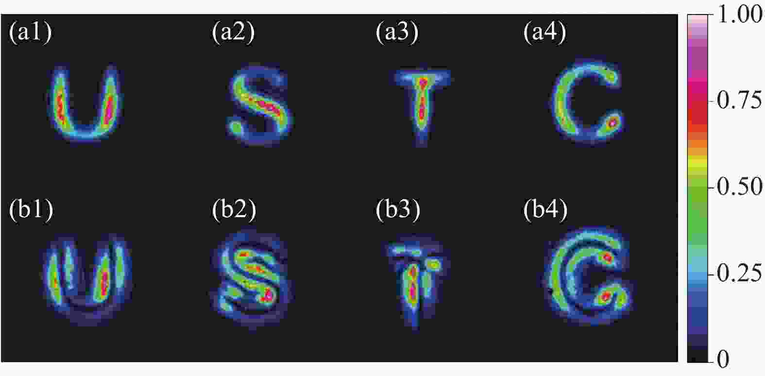
图 8 泵浦光具有不同空间模式时的成像结果。(a1)~(a4)泵浦光为高斯模式,实现了对光透过物体部分的成像;(b1)~(b4)泵浦光为拉盖尔-高斯模式,实现了对中红外信号光的边缘增强成像
Figure 8. Imaging results of pump with different spatial modes. (a1)-(a4) Pump is in Gaussian mode, achieving imaging of the signal passing through the object; (b1)-(b4) Pump is in Laguerre-Gaussian mode, achieving edge enhanced imaging of mid-infrared signal
-
上转换中红外成像方法具有灵敏度高、响应速度快等优点,因此对热辐射物体可以进行高帧率的连续视频成像,并能够据此分析物体的温度等信息。
将蜡烛点燃置于透镜f1的前焦面处,能够实现对蜡烛烛焰的实时成像。如图9所示,根据成像的强度能明显观察到蜡烛烛焰的温度分布特点;并且能够实时跟踪烛焰在外界气流干扰下的摆动,以及成像亮度随温度变化的影响。

图 9 蜡烛烛焰实时成像视频截图。(a)无外界气流扰动时烛焰竖直燃烧; (b)、(c)烛焰受到气流扰动时出现摆动
Figure 9. Screenshot of real-time imaging video of candle flames. (a) When there is no external airflow disturbance, the candle flame burns vertically; (b), (c) The candle flame oscillates when disturbed by airflow
图10(a)~(c)中展示了在背景存在其它热源干扰时的温度目标探测。通过调节输入电流可对电烙铁进行控温,利用上转换的方法实时监测电烙铁的温度变化。当电烙铁温度高于背景温度时,电烙铁区域亮度高于背景;随着电烙铁温度下降,电烙铁区域逐渐融入背景中,此时电烙铁温度等于背景温度;电烙铁温度继续下降,当电烙铁温度低于背景时,则在明亮背景中出现电烙铁的阴影区。如图10(d)~(f)所示,通过定标后,可以直接通过亮度判读物体的温度,(d)、(e)、(f)的温度分别为333 、453、763 K。
利用上转换成像方法对提高温度分辨率亦有优势,目前通过这种方法实现了噪声等效温差约为50 mK的上转换成像系统[25]。

图 10 不同温度电烙铁在热背景中的成像结果。(a)电烙铁温度高于背景;(b)电烙铁温度近似等于背景温度;(c)电烙铁温度低于背景温度;(d)~(f)烙铁在室温背景下成像结果,对应温度分别为333 、453、763 K
Figure 10. Imaging results of soldering irons at different temperatures in a thermal background. (a) The temperature of the soldering iron is higher than the background; (b) The temperature of the soldering iron is approximately equal to the background temperature; (c) The temperature of the soldering iron is lower than the background temperature; (d)-(f) Imaging results of soldering iron under room temperature background, corresponding to temperatures of 333, 453, and 763 K, respectively
-
文章研究了基于啁啾极化晶体的中红外图像频率上转换探测过程及其成像特性分析。系统分析了上转换成像理论,给出了清晰的物理模型以及数值求解方法,分析了各种影响因素对成像结果的影响,并通过数值模拟对中红外上转换的接受带宽和视场角等参数进行了理论预测,进一步与实验结果进行了比较。实验利用啁啾极化晶体,实现了中红外接受带宽597 nm,视场角16.59°的上转换成像探测;通过对比传统碲镉汞中红外探测器,证实了上转换成像技术在提高成像信噪比和灵敏度方面具有明显优势,并利用1.05×10⁵ Hz的光子通量实现了中红外的弱光成像。文中进一步展示了上转换成像系统对相关光和非相干光照明物体的具体应用:对中红外相干光照明物体,利用成熟的近红外器件对泵浦光空间模式进行操作实现了光学边缘增强成像;对非相干照明物体实现了实时视频帧率的成像,能够实时监测物体的形状变化,并能够分析其温度特征。
这项工作对基于上转换红外成像系统进行了较为全面研究,将为各种应用场景设计和改进系统设计提供依据,有望在天文学、遥感、显微等领域发挥更重要的作用。
Mid-infrared up-conversion imaging based on chirp polarization crystals
-
摘要: 将物体辐射或反射的中红外波段光转换到可见光区域、再利用高性能的硅基器件探测是一种有效的目标识别手段,规避了传统半导体中红外探测器在灵敏度、深制冷和噪声等性能方面的不足。文中利用啁啾极化的非线性晶体,在强连续泵浦光作用下,将中红外波段的光场信息高效、高保真地迁移到可见光域进行探测。通过建立简单的物理模型,理论上讨论了啁啾极化晶体参数对上转换成像性能的影响,并进行了数值仿真;通过实验进一步研究了啁啾晶体上转换方法在转换带宽、成像视场等成像关键参数上的优势,实验结果与理论计算值吻合较好。通过上转换方法,演示了相干光与非相干光照明条件下目标探测,实现了相干光照明下的光学边缘增强成像和非相干照明下的热辐射目标识别。这一工作对基于啁啾晶体的上转换成像系统的理解、设计和实际应用具有重要参考价值。Abstract:
Objective The mid-infrared band (2.5-25 μm) has important applications in the field of spectroscopy and imaging. Spectral migration technique up-converts mid-infrared signal light to visible/near-infrared light through a non-linear frequency process, which is then detected using high-performance detectors based on wide-band gap materials such as silicon. Compared to schemes directly using traditional semiconductor detectors, this technique has the advantages of fast response and room temperature operation. Bulk crystals have large aperture to realize array detection. In particular, chirped polarized crystals have obvious advantages in imaging acceptance bandwidth and field of view due to their large phase-matching bandwidth. Previous up-conversion imaging theory, however, didn't consider the nonlinear process of signal light in the crystal to affect the propagation. Therefore, there is some deviation between the theoretical analysis and the up-conversion imaging results under the weak signal light condition. Based on the basic imaging principle, a simple physical model of the up-conversion imaging process is presented by solving the coupled wave equation using finite difference method and considering the effect of nonlinear process on the optical propagation. On this basis, a theoretical derivation for up-conversion imaging under coherent/incoherent radiation illumination conditions based on chirped polarized crystals is provided. Methods A mid-infrared up-conversion detection imaging system based on a chirped polarized crystal is built (Fig.3). The target object is illuminated by the thermal radiation of an electric soldering iron, then the visible light in the signal is filtered out by a band pass filter (BP1). A strong 1 080 nm pump light is directed into the crystal through a dichroic mirror (DM) along with the signal beam. Through a 4f system, the up-conversion results of the target are imaged on the EMC CD. A chirped polarized lithium niobate (CPLN) crystal with a period interval of 0.01 μm and a period range of 21.6-23.4 μm is used in the experiment. The length of the crystals is 40 mm and the cross section size is 2 mm×3 mm. The temperature of CPLN crystal is controlled by a home-made temperature controller, whose fluctuation is ±0.002 ℃. Results and Discussions By using a mature spectrometer to measure the spectrum after up-conversion and combining with the law of conservation of energy, the accepted spectrum of the up-conversion process in the corresponding mid-infrared band can be obtained (Fig.4). The corresponding mid-infrared acceptance range is 2 915-3 512 nm, and its full-width of half-max (FWHM) is 597 nm. Due to the low transmittance of the DM at wavelengths greater than 3 400 nm, the actual conversion bandwidth is larger than the direct measurement results, which is in agreement with the numerical calculation results (Fig.2). In contrast, the wavelength acceptance bandwidth of single-period polarized crystals is only on the order of nanometers. In the up-conversion imaging results (Fig.5), the largest one-dimensional size of the target is 3.62 cm, corresponding to 125 mm propagation distance, thus the full angle of the field of view is 16.59°, which is slightly smaller than the numerical calculation result in Fig.2. Under the condition of weak signal light, the background of pattern directly imaged by mid-infrared light through the mercury cadmium telluride thermal imager is full of white noise, making it difficult to identify the target contour information, while the pattern obtained by the up-conversion method with the same power of light has clean background and high signal-to-noise ratio (SNR), which also can realize high SNR of the single photon level imaging (Fig.6-7). In addition, applications of up-conversion imaging under coherent/incoherent radiation illumination conditions are reported. The optical edge enhancement imaging is realized for the objects illuminated by mid-infrared coherent light (Fig.8). Real-time video frame rate imaging of incoherent illuminated objects is realized, and its temperature characteristics can be analyzed (Fig.9). Conclusions In the experiment, chirped polarized crystal is used to realize the up-conversion imaging detection of the mid-infrared receiving bandwidth of 597 nm and the field angle of view of 16.59°. By comparing with traditional mercury cadmium telluride mid-infrared detector, the up-conversion imaging technique has obvious advantages in improving the signal-to-noise ratio and sensitivity of imaging, and the low-light imaging of mid-infrared is realized by using the photon flux of 1.05×10⁵ Hz. The paper further shows the application of the up-conversion imaging system to the objects illuminated by correlation light and incoherent light. This work has conducted a comprehensive study on the up-conversion based infrared imaging system, which will provide a basis for the design of various application scenarios and improve the system design. -
Key words:
- mid-infrared imaging /
- up-conversion /
- chirped polarization crystal /
- bandwidth /
- efficiency
-
图 2 铌酸锂晶体处于30 ℃,在1080 nm泵浦光作用下,不同极化周期对应的相位匹配波长和角度的关系图
Figure 2. The relationship between phase matching wavelength and half-angle of the field of view with different polarization periods of lithium niobite (LN) crystal at 30 ℃ under the action of 1080 nm pump beam
图 3 实验装置示意图。(a)实验光路图;(b)啁啾极化晶体结构示意图
Figure 3. Schematic diagram of the experimental setup. (a) Experimental configuration diagram; (b) Schematic diagram of chirp polarization crystal structure
图 4 直接探测上转换光所得光谱图
Figure 4. Directly detecting the spectrum obtained from up-conversion beam
图 6 中红外光直接探测与上转换探测结果对比。(a)碲镉汞热像仪成像结果;(b)上转换后硅基EMCCD成像结果
Figure 6. Comparison of results between direct detection up-conversion detection of mid-infrared signal. (a) Imaging results of MCT thermal imager; (b) Imaging result of Si based EMCCD after up-conversion
图 7 中红外光单光子量级上转换成像结果。(a)、(b)、 (c)、 (d)分别为字母“U”、“S”、“T”、“C”
Figure 7. Single-photon level up-conversion imaging results of mid-infrared signal. (a) (b), (c), and (d) are the letters "U", "S", "T", and "C", respectively
图 8 泵浦光具有不同空间模式时的成像结果。(a1)~(a4)泵浦光为高斯模式,实现了对光透过物体部分的成像;(b1)~(b4)泵浦光为拉盖尔-高斯模式,实现了对中红外信号光的边缘增强成像
Figure 8. Imaging results of pump with different spatial modes. (a1)-(a4) Pump is in Gaussian mode, achieving imaging of the signal passing through the object; (b1)-(b4) Pump is in Laguerre-Gaussian mode, achieving edge enhanced imaging of mid-infrared signal
图 9 蜡烛烛焰实时成像视频截图。(a)无外界气流扰动时烛焰竖直燃烧; (b)、(c)烛焰受到气流扰动时出现摆动
Figure 9. Screenshot of real-time imaging video of candle flames. (a) When there is no external airflow disturbance, the candle flame burns vertically; (b), (c) The candle flame oscillates when disturbed by airflow
图 10 不同温度电烙铁在热背景中的成像结果。(a)电烙铁温度高于背景;(b)电烙铁温度近似等于背景温度;(c)电烙铁温度低于背景温度;(d)~(f)烙铁在室温背景下成像结果,对应温度分别为333 、453、763 K
Figure 10. Imaging results of soldering irons at different temperatures in a thermal background. (a) The temperature of the soldering iron is higher than the background; (b) The temperature of the soldering iron is approximately equal to the background temperature; (c) The temperature of the soldering iron is lower than the background temperature; (d)-(f) Imaging results of soldering iron under room temperature background, corresponding to temperatures of 333, 453, and 763 K, respectively
-
[1] Cheng Z, Qin C, Wang F, et al. Progress on mid-IR graphene photonics and biochemical applications [J]. Frontiers of Optoelectronics, 2016, 9(1): 259-269. doi: 10.1007/s12200-016-0618-z [2] Lu F, Jin M, Belkin M. Tip-enhanced infrared nanospectroscopy via molecular expansion force detection [J]. Nature Photonics, 2014, 8(4): 307-312. doi: 10.1038/nphoton.2013.373 [3] Wrobel T P, Bhargava R. Infrared spectroscopic imaging advances as an analytical technology for biomedical sciences [J]. Analytical Chemistry, 2018, 90(3): 1444-1463. doi: 10.1021/acs.analchem.7b05330 [4] 张荞, 孙晓兵, 洪津, 等 . 中波红外土壤含水量的光谱偏振特性 [J]. 红外与毫米波学报,2013 ,32 (6 ):502 -507 . doi: 10.3724/SP.J.1010.2013.00502 Zhang Qiang, Sun Xiaobing, Hong Jin, et al. Polarization spectral characteristics of soil surface moisture in the mid-wave infrared range [J]. Journal of Infrared and Millimeter Waves, 2013, 32(6): 502-507. (in Chinese) doi: 10.3724/SP.J.1010.2013.00502[5] Spitz O, Didier P, Durupt L, et al. Free-space communication with directly modulated mid-infrared quantum cascade devices [J]. IEEE Journal of Selected Topics in Quantum Electronics, 2022, 28(1): 1200109. doi: 10.1109/JSTQE.2021.3096316 [6] Barh A, Rodrigo P J, Meng L, et al. Parametric upconversion imaging and its applications [J]. Advances in Optics and Photonics, 2019, 11(4): 952-1019. doi: 10.1364/AOP.11.000952 [7] Han Z, Zhou Z, Shi B. Quantum frequency transducer and its applications [J]. Advanced Devices & Instrumentation, 2023, 4(1): 0030. doi: 10.34133/adi.0030 [8] Liu S, Yang C, Liu S, et al. Up-conversion imaging processing with field-of-view and edge enhancement [J]. Physical Review Applied, 2019, 11(4): 044013. doi: 10.1103/PhysRevApplied.11.044013 [9] Zhou Z, Li Y, Ding D, et al. Orbital angular momentum photonic quantum interface [J]. Light: Science & Applications, 2016, 5(1): e16019. doi: 10.1038/lsa.2016.19 [10] Mancinelli M, Trenti A, Piccione S, et al. Mid-infrared coincidence measurements on twin photons at room temperature [J]. Nature Communications, 2017, 8(1): 15184. doi: 10.1038/ncomms15184 [11] Wang Y, Huang K, Fang J, et al. Mid-infrared single-pixel imaging at the single-photon level [J]. Nature Communications, 2023, 14(1): 1073. doi: 10.1038/s41467-023-36815-3 [12] Neely T W, Nugent-Glandorf L, Adler F, et al. Broadband mid-infrared frequency upconversion and spectroscopy with an aperiodically poled LiNbO3 waveguide [J]. Optics Letters, 2012, 37(20): 4332-4334. doi: 10.1364/OL.37.004332 [13] Ge Z, Han Z, Liu Y, et al. Midinfrared up-conversion imaging under different illumination conditions [J]. Physical Review Applied, 2023, 20(5): 054060. doi: 10.1103/PhysRevApplied.20.054060 [14] Friis S M M, Hogstedt L. Upconversion-based mid-infrared spectrometer using intra-cavity LiNbO3 crystals with chirped poling structure [J]. Optics Letters, 2019, 44(17): 4231-4234. doi: 10.1364/OL.44.004231 [15] Bostani A, Tehranchi A, Kashyap R. Super-tunable, broadband up-conversion of a high-power CW laser in an engineered nonlinear crystal [J]. Scientific Reports, 2017, 7(1): 883. doi: 10.1038/s41598-017-00974-3 [16] Torregrosa A J, Karamehmedovic E, Maestre H, et al. Up-conversion sensing of 2D spatially-modulated infrared information-carrying beams with Si-based cameras [J]. Sensors, 2020, 20(12): 3610. doi: 10.3390/s20123610 [17] Pedersen C, Karamehmedovic E, Dam J S, et al. Enhanced 2D-image upconversion using solid-state lasers [J]. Optics Express, 2009, 17(23): 20885-20890. doi: 10.1364/OE.17.020885 [18] Dam J S, Pedersen C, Tidemand-Lichtenberg P. Theory for upconversion of incoherent images [J]. Optics Express, 2012, 20(2): 1475-1482. doi: 10.1364/OE.20.001475 [19] Junaid S, Tomko J, Semtsiv M P, et al. Mid-infrared upconversion based hyperspectral imaging [J]. Optics Express, 2018, 26(3): 2203-2201. doi: 10.1364/OE.26.002203 [20] Maestre H, Torregrosa A J, Fernández-Pousa C R, et al. IR-to-visible image upconverter under nonlinear crystal thermal gradient operation [J]. Optics Express, 2018, 26(2): 1133-1144. doi: 10.1364/OE.26.001133 [21] Shen Y R. The Principles of Nonlinear Optics[M]. New York: Wiley, 1984. [22] Boyd R W. Nonlinear Optics[M]. Orlando: Academic Press, 2008. [23] Zhou Z, Li Y, Ding D, et al. Generation of light with controllable spatial patterns via the sum frequency in quasi-phase matching crystals [J]. Scientific Reports, 2014, 4(1): 5650. doi: 10.1038/srep05650 [24] Ge Z, Yang C, Li Y, et al. Up-conversion detection of mid-infrared light carrying orbital angular momentum [J]. Chinese Physics B, 2022, 31(10): 104210. doi: 10.1088/1674-1056/ac6eda [25] Ge Z, Zhou Z, Ceng J, et al. Thermal camera based on frequency upconversion and its noise-equivalent temperature difference characterization [J]. Advanced Photonics Nexus, 2023, 2(4): 046002. doi: 10.1117/1.APN.2.4.046002 -

 点击查看大图

计量
- 文章访问数: 101
- HTML全文浏览量: 12
- PDF下载量: 43
- 被引次数: 0

