


-
磁流变抛光技术(magnetorheological finishing, MRF)作为新型的光学加工技术[1−4],具有加工确定性高、收敛效率稳定、边缘效应可控、亚表面破坏层小等诸多优点[5−10],因而在高精度光学加工领域有着广泛的应用[11−15]。由磁流变加工原理可知,高精度的加工过程需要稳定的去除函数和各个驻留点位精确的驻留时间分布,而实际加工过程往往受各类误差的影响,使得实际加工得到的结果与理想结果存在偏差。在高精度加工领域,较小的误差也会对面形精度以及各频段误差造成很大的影响,甚至会导致面形误差的不收敛。
随着非球面光学元件的不断发展,其在各类光学系统中的应用不断增多。与球面光学元件相比,非球面光学元件具有校正像差、提升像质、减少系统重量等优点,因而得到了广泛应用[16−19]。但非球面光学元件表面复杂,制造过程较球面元件更困难。
现有研究中,磁流变对非球面光学元件的加工均通过检测加工的循环过程实现,但其存在加工后面形精度不确定性和中频误差不可控的问题[20−24]。
传统的磁流变抛光工艺由于存在各类误差的影响,导致加工结果存在不确定性,无法实现对加工后面形精度的量化判断。为减少磁流变抛光过程中误差对加工精度的影响以及实现对中频误差的抑制,采用基于不确定度误差的加工工艺方法对非球面加工中去除函数误差不确定度与位置误差不确定度进行理论分析,并通过实验验证与误差补偿,验证了该方案的可行性,得到理想的面形精度值。
-
在实际加工过程中,工艺参数的不稳定性会造成去除函数的变化,从而导致加工过程以及加工后面形精度与中频误差的不确定性。为提高磁流变加工过程的修形精度,降低加工过程中导致的中频误差,在磁流变加工过程中对去除函数误差进行分析,找出去除函数误差的影响规律。去除函数不确定度误差包含形状误差和效率误差。
-
去除函数用以单位时间内对光学元件表面材料的去除,通过控制驻留时间实现对表面材料的定量去除。根据计算机控制光学表面成型(computer controlled optical surfacing, CCOS)理论,磁流变加工过程中材料的去除量表示为去除函数与驻留时间的卷积过程:
$$ E(x,y) = Z(x,y) - R(x,y) * T(x,y) $$ (1) 式中:$ Z\left( {x,y} \right) $为光学元件初始面形误差;$ R\left( {x,y} \right) $为去除函数;$ T\left( {x,y} \right) $为驻留时间函数;$ E\left( {x,y} \right) $为残留误差。
加工过程中存在各类误差的影响,导致实际加工时去除函数的形状与理论分析的去除函数形状存在偏差。用$ \alpha $、$ \beta $分别表示去除函数在X方向和Y方向的误差系数,即误差因子,${R_m}(x,y)$表示实际加工过程中的去除函数,表达式如下:
$$ {R_m}(x,y) = R(\alpha x,\beta y) $$ (2) 因此,在形状误差影响下,实际加工过程的残留误差$ {E_m}(x,y) $为:
$$ \begin{split} {E_m}(x,y) &= Z(x,y) - {R_m}(x,y) * T(x,y) =\\& Z(x,y) - R(\alpha x,\beta y) * T(x,y)=\\& E(x,y) + R(x,y) * T(x,y) - R(\alpha x,\beta y) * T(x,y) =\\& E(x,y) + [R(x,y) - R(\alpha x,\beta y)] * T(x,y) \end{split} $$ (3) 去除函数形状误差会导致在实际加工过程中引入额外残差,从而造成实际残留误差值变大。
-
在磁流变加工的理论分析时,各种工艺参数如抛光轮转速,抛光液流量、粘度,磁场强度等都是恒定不变的。但在实际加工工艺中,被加工光学元件的材料特性以及工艺参数的不稳定性会导致实际加工过程中的去除函数与理论分析过程中的去除函数存在偏差,该误差便为效率误差。${R_n}(x,y)$表示实际加工过程中的去除函数,将其与理论分析过程中的去除函数$ R\left( {x,y} \right) $的比值定义为效率因子$\delta $,为:
$$ \delta = {R_n}(x,y)/R(x,y) $$ (4) 因此,在效率误差影响下,实际加工过程的残留误差${E_n}(x,y)$为:
$$ \begin{split} {E_n}(x,y)& = Z(x,y) - {R_n}(x,y) * T(x,y) =\\& E(x,y) + R(x,y) * T(x,y) - (\delta R(x,y)) * T(x,y) =\\& E(x,y) + (1 - \delta )(R(x,y) * T(x,y)) =\\& E(x,y) + (1 - \delta )(Z(x,y) - E(x,y)) =\\& Z(x,y) - \delta (Z(x,y) - E(x,y))= \\& (1 - \delta )Z(x,y) + \delta E(x,y) \end{split} $$ (5) 去除函数效率误差会导致在实际加工过程中引入额外残差,从而造成实际残留误差值变大。
-
由于在磁流变加工过程中,光学元件的机床坐标系与工件坐标系不可能完全重合,导致去除函数的实际加工位置与理论仿真位置存在偏差,从而影响磁流变定点进行误差去除的确定性。
如图1所示,假设去除函数在机床坐标下的位置点为${G_m}({x_m},{y_m},1)$,而在工件坐标系下的位置点为${G_n}({x_n},{y_n},1) $,则机床坐标系与工件坐标系存在如下关系:
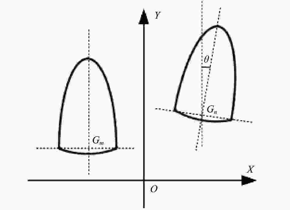
图 1 磁流变去除函数定位误差示意图
Figure 1. Schematic diagram of removing function positioning error
$$ {G_n}({x_n},{y_n},1) = {G_m}({x_m},{y_m},1) \cdot {\boldsymbol{T}} $$ (6) 其中,矩阵T可表示为:
$$ {\boldsymbol{T}} = \left[ {\begin{array}{*{20}{c}} 1&0&{{\delta _x}} \\ 0&1&{{\delta _y}} \\ 0&0&1 \end{array}} \right] \cdot \left[ {\begin{array}{*{20}{c}} {\cos \theta }&{ - \sin \theta }&0 \\ {\sin \theta }&{\cos \theta }&0 \\ 0&0&1 \end{array}} \right] $$ (7) 由此可得以下方程式:
$$ \left\{ {\begin{array}{*{20}{c}} {{x_n} = {x_m} \cdot \cos \theta - {y_m} \cdot \sin \theta + {\delta _x}} \\ {{y_n} = {x_m} \cdot \sin \theta + {y_m} \cdot \cos \theta {\text{ + }}{\delta _{{y}}}} \end{array}} \right. $$ (8) 式中:$ {\delta _x} $和$ {\delta _y} $为X方向与Y方向移位;$\theta $为角度误差。
理论抛光过程中的去除函数为$R(x,y)$,而实际抛光过程中的去除函数${R_r}(x,y)$为:
$$ {R_r}(x,y) = R(x - {\delta _x},y - {\delta _y}) $$ (9) 根据公式(1),采用磁流变抛光去除函数进行面形误差修正时,由位置误差引起的面形误差$E(x,y)$为:
$$\begin{split} E(x,y) &= Z(x,y) - R(x - {\delta _x},y - {\delta _y}) * T(x,y)= \\& \left(\frac{{\partial R}}{{\partial x}} \cdot {\delta _x} + \frac{{\partial R}}{{\partial y}} \cdot {\delta _y}\right) * T(x,y) \end{split} $$ (10) 从图1中可以看出,去除函数会存在偏差,而去除函数的偏移存在X轴和Y轴两个方向。由仿真分析可知,X轴方向(图2(c)和图2(d))和Y轴方向(图2(e)和图2(f))的偏差几乎一致,因此文中选取X轴方向进行仿真与实验分析。

图 2 (a) 光学元件原始面形误差;(b) 去除函数加工后面形误差;(c) 去除函数沿X轴偏转1°加工后面形误差;(d) 去除函数沿X轴偏转2°加工后面形误差;(e) 去除函数沿Y轴偏转1°加工后面形误差;(f) 去除函数沿Y轴偏转2°加工后面形误差
Figure 2. (a) The original surface error of the optical element; (b) The surface error obtained after the removal function processing; (c) The surface error obtained after the removal function was deflected 1° along the X-axis; (d) The surface error obtained after the removal function was deflected 2° along the X-axis; (e) The surface error obtained after the removal function was deflected 1° along the Y-axis; (f) The surface error obtained after the removal function was deflected 2° along the Y-axis
对加工过程中的去除函数误差进行理论分析,利用误差的不确定度来指导加工工艺,通过仿真分析和实验相结合的方式获取加工中的不确定度,并通过验证实验达到理想的面形误差收敛值。
-
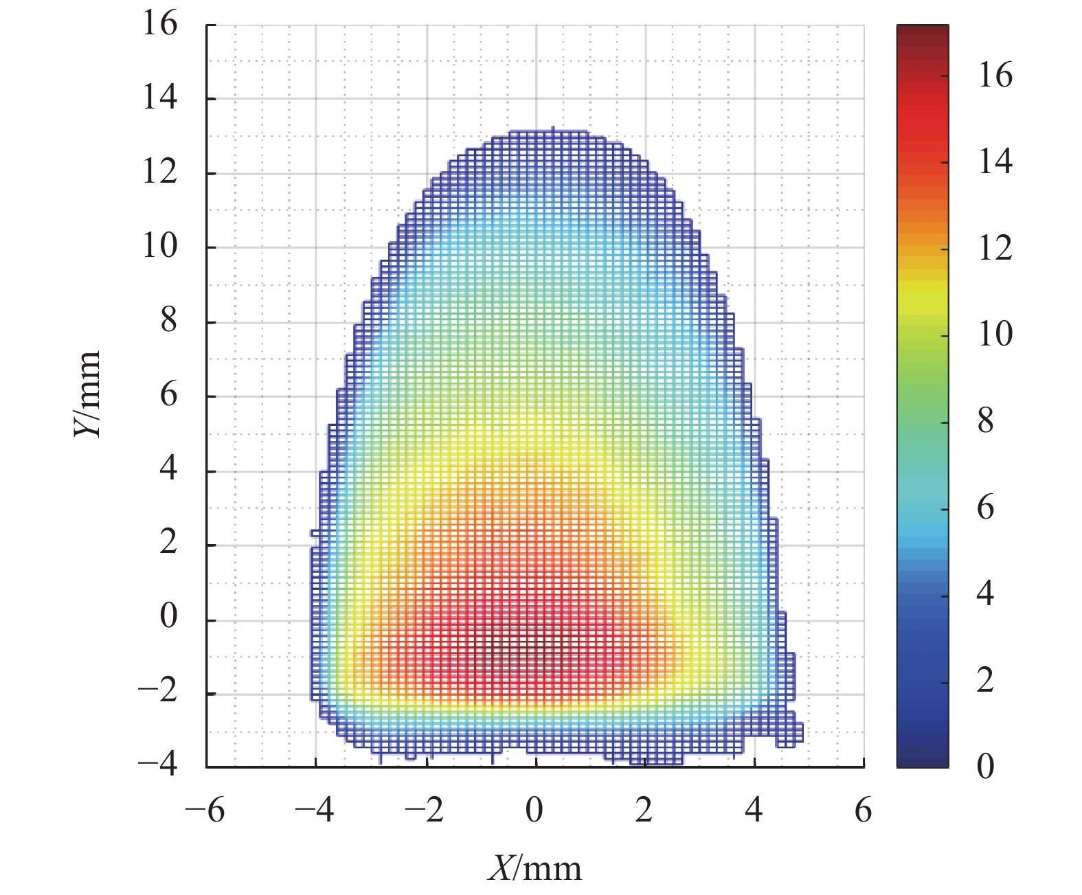
为验证不确定度方法的有效性,通过仿真分析和实验验证实现对磁流变加工中误差不确定度值的评估。在对去除函数不确定度误差和位置不确定度误差进行理论分析后,使用去除函数进行工艺仿真与实验,其大小为15 mm×10 mm,去除率为0.95 mm3/min,如图3所示。

图 3 磁流变抛光去除函数
Figure 3. Removal function of MRF finishing
通过采用栅线扫描路径完成非球面镜#A的磁流变加工,加工和检测平台如图4(a)和4(b)所示,非球面镜#A详细技术参数如表1所示。

图 4 (a) 磁流变加工及(b) 面形检测过程
Figure 4. Process of (a) magnetorheological finishing and (b) surface shape detection
表 1 非球面镜#A技术参数
Table 1. Technical parameters of off-axis aspheric #A
Parameter Value Diameter/mm 145 Radius of curvature/mm −425.17 Quadric constant −1 Off-axis quantity/mm 121.23 为了得到非球面镜的初始面形误差分布,采用非接触式3D光学面形测量系统LuphoScan对该非球面镜进行测量。初始面形误差如图5(a)所示,面形误差RMS值为163.842 nm。磁流变加工过程中,光学系统对中频段的误差也有一定的要求,因此按照系统加工需求,保证光学系统对小角度散射最为敏感,将滤波范围窗口设为0.04 ~0.4 mm−1。滤波后得到初始面形的中频误差RMS值为29.833 nm,如图5(b)所示。

图 5 #A(a)初始面形误差及(b)初始面形中频误差
Figure 5. (a) Initial surface error and (b) initial mid-spatial error of #A
在进行初始面形测量后,为了分析利用去除函数加工后的面形误差以及中频误差,进行磁流变仿真加工,仿真加工后的面形数据如图6所示,面形误差RMS值为16.4764 nm,经滤波后得到初始面形的中频误差RMS值为10.346 nm。
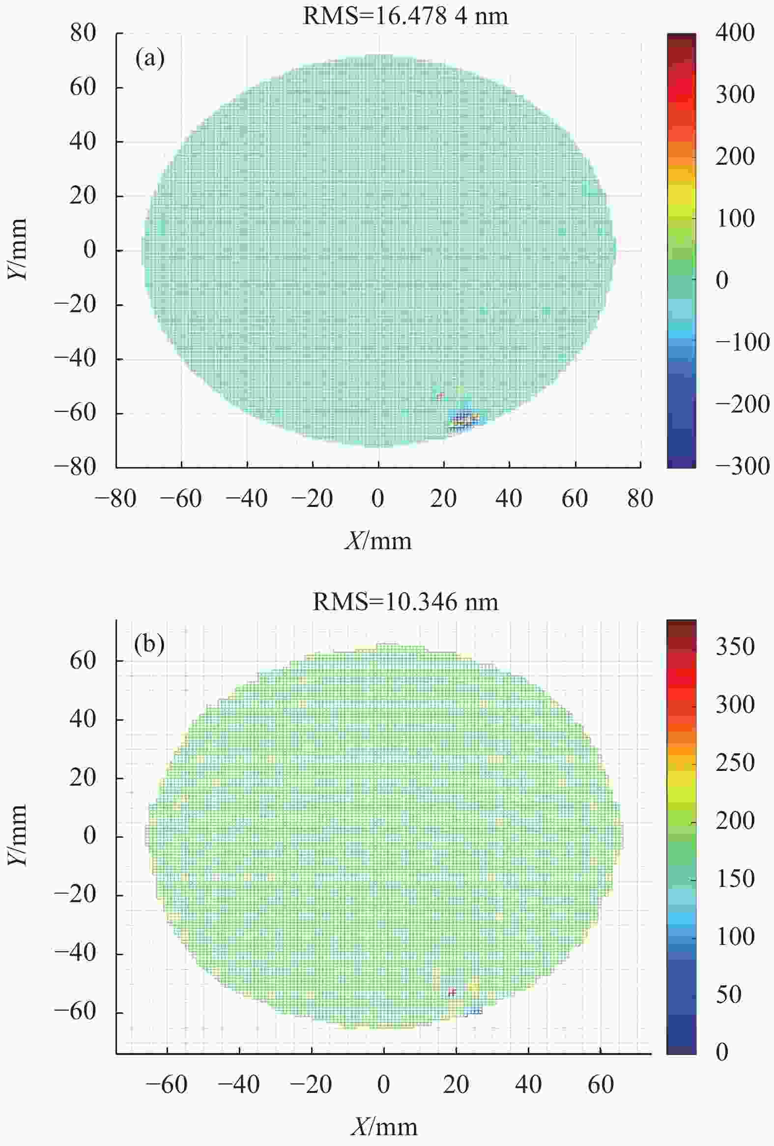
图 6 #A仿真加工后(a)面形误差及(b)中频误差
Figure 6. (a) Surface error and (b) mid-spatial error after simulation processing of #A
在仿真分析的基础上,为了获得加工过程中的不确定度误差值,对该非球面镜进行修形实验,将实验结果与仿真结果对比,得到量化的不确定度值。磁流变抛光的具体工艺参数如表2所示。
表 2 磁流变抛光工艺参数
Table 2. Parameters of magnetorheological finishing
Parameter Value Diameter of polishing wheel/mm 200 Polishing wheel speed/rpm 170 Current intensity/A 7 Quantity of flow/L·min−1 120 Magnetorheological fluid viscosity/cp 190 Pressing depth/mm 0.1 将加工结果用以分析磁流变抛光的不确定度下的面形误差以及中频误差。#A通过五次迭代加工,其中包括四次磁流变抛光工艺和一次平滑工艺,加工过程如图7所示。其中图7(e)为最终的加工面形,面形精度RMS值为20.102 nm,图7(f)为最终加工面形所包含的中频误差,中频误差RMS值为13.961 nm。
将加工结果与仿真结果相比,面形误差RMS值与中频误差RMS值均存在3.5 nm的不确定度误差值。不确定度误差结果可为后续磁流变抛光非球面光学元件过程中对面形误差以及中频误差的抑制提供指导。
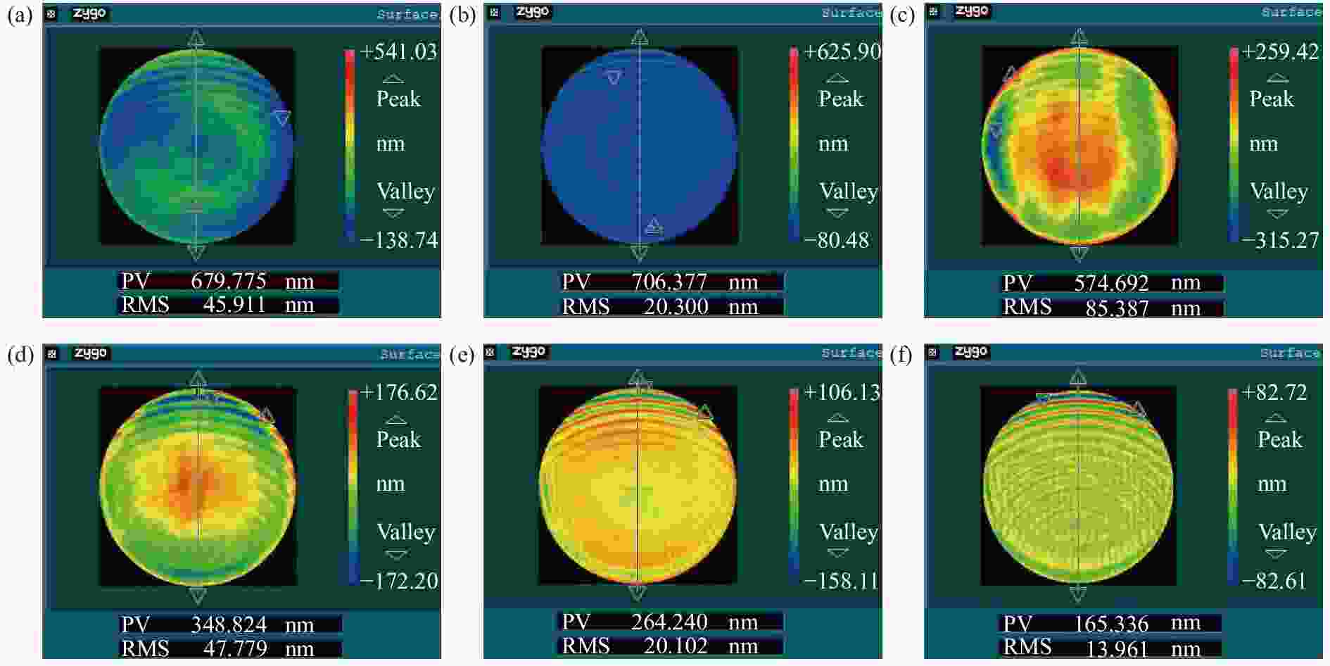
图 7 #A实际加工后面形。 (a) 第一次磁流变加工后面形;(b) 第二次磁流变加工后面形;(c) 平滑后面形;(d) 第三次磁流变加工后面形;(e) 第四次磁流变加工后面形;(f) 第四次磁流变加工后中频误差
Figure 7. Actual machining surface of #A. (a) After the first magnetorheological finishing; (b) After the second magnetorheological finishing; (c) After the smooth processing; (d) After the third magnetorheological finishing; (e) After the fourth magnetorheological finishing; (f) Mid-spatial error after the fourth magnetorheological finishing
-
由于不确定度误差的存在会影响磁流变加工精度,并且易在面形误差收敛的同时引入中频误差。因此,为实现精确控制加工,基于误差不确定度建立不确定度误差下的加工工艺,图8为基于不确定度误差磁流变抛光工艺流程图。

图 8 不确定度误差下加工工艺流程图
Figure 8. Process flow chart under uncertainty error
为验证不确定度工艺以及不确定度值在实际生产加工过程中的应用,对非球面镜#B进行加工实验,通过对实际加工后#A的不确定度分析,进行#B的加工不确定度仿真预测,并通过实验得到加工后的面形以及中频误差。
不确定度验证实验中所使用的非球面镜#B技术参数与#A一致,采用非接触式3D光学面形测量系统LuphoScan对该非球面镜进行测量,得到初始面形误差如图9(a)所示,面形误差RMS值为170.743 nm,经滤波后得到初始面形的中频误差RMS值为31.743 nm,如图9(b)所示。

图 9 #B(a)初始面形误差及(b) 中频误差
Figure 9. (a) Initial surface and (b) initial mid-spatial error of #B
得到非球面镜#B的初始面形分布后,对其进行磁流变仿真加工,得到仿真加工后的面形数据如图10所示,面形误差RMS值为15.4327 nm,经滤波后得到初始面形的中频误差RMS值为10.262 nm。由上一节不确定度误差工艺实验可知,加工后面形残差以及中频误差存在3.5 nm的加工不确定度。由此可得,在对#B进行实际加工工艺后,面形误差RMS值为20 nm左右,中频误差RMS值为14 nm左右。

图 10 #B仿真加工后(a) 面形误差及(b)中频误差
Figure 10. (a) Surface error and (b) mid-spatial error after simulation processing of #B
为验证加工不确定度误差工艺,对非球面镜#B进行修形验证实验,磁流变抛光的具体工艺参数如表2所示。#B通过七次迭代加工,如图11所示,其中包括五次磁流变抛光工艺和两次平滑工艺。图11(g)为最终的加工面形,面形精度RMS值为19.317 nm,图11(h)为最终加工面形所包含的中频误差,中频误差RMS值为13.282 nm。由此可得,在对#B进行实际加工工艺后,面形误差和中频误差达到了不确定度下的RMS值。

图 11 #B实际加工后面形。 (a) 第一次磁流变加工后面形;(b) 第二次磁流变加工后面形;(c) 平滑后面形;(d) 第三次磁流变加工后面形;(e) 第二次平滑后面形;(f) 第四次磁流变加工后面形;(g) 第五次磁流变加工后面形;(h) 第五次磁流变加工后中频误差
Figure 11. Actual machining surface of #B. (a) After the first magnetorheological finishing; (b) After the second magnetorheological finishing; (c) After the first smooth processing; (d) After the third magnetorheological finishing; (e) After the second smooth processing; (f) After the fourth magnetorheological finishing; (g) After the fifth magnetorheological finishing; (h) Mid-spatial error after the fifth magnetorheological finishing
由仿真结果对#B的误差不确定度分析表明,在实际加工后,中频误差RMS可以抑制到14 nm左右,但经过第一次平滑后,使用磁流变加工(图11(d)),中频误差RMS值为15.158 nm,如图12(a)所示。
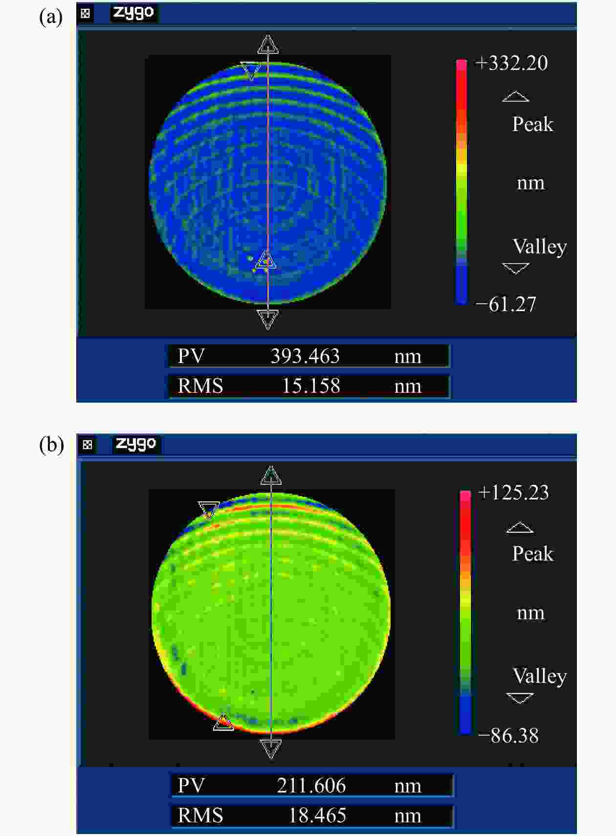
图 12 #B实际加工中频误差。 (a) 图11(d)中包含中频误差;(b) 图11(e)中包含中频误差
Figure 12. Actual machining mid-spatial error of #B. (a) Mid-spatial error in Fig.11(d); (b) Mid-spatial error in Fig.11(e)
由此可知,后续加工可达到的中频不仅不会下降至预期值(14 nm左右),还可能会恶化,因此#B需进行第二次平滑,使中频误差达到预期值(图11(e))。中频误差RMS值达到18.465 nm后,如图12(b)所示,才可作为理想的面形以做后续磁流变加工处理,直至加工完成,达到不确定度下的面形精度。
在不确定度误差下进行了#B磁流变加工工艺实验,加工后与加工前预测结果相比,面形误差RMS值从15.4327 nm增加到19.317 nm,面形误差RMS值的不确定误差控制在3.8843 nm;中频误差RMS值从10.262 nm增加到13.282 nm,中频误差RMS值的不确定误差控制在3.02 nm。实验结果表明,基于不确定度误差的方法,不仅面形误差得到了有效收敛,同时中频误差得到了合理的抑制,为磁流变加工过程中的面形误差以及中频误差的抑制提供了理论支撑。该方法对于实现高精度光学元件磁流变加工具有重要的实用价值。
-
文中对磁流变加工中的不确定度理论进行了分析,并具体分析了去除函数不确定度误差与位置不确定度误差,总结了不确定度误差下磁流变加工工艺流程。在此基础上,为验证不确定度误差工艺方法的可行性,对两块非球面镜进行了验证实验。对非球面#A的磁流变加工过程中的误差进行了详细分析,用以确定磁流变加工非球面中的不确定度,从而指导非球面#B的加工。由实验验证了非球面#B的面形精度满足工程需求。在不确定度分析的基础上优化了工艺流程,通过磁流变加工不确定度工艺方法,在达到面形误差收敛的同时实现了中频误差的抑制。
Uncertainty error technology for magnetorheological finishing of optical elements
-
摘要: 为减少磁流变抛光过程中误差对加工精度的影响,实现光学元件磁流变高精度加工,采用一种不确定度误差工艺方法对加工中的误差进行抑制。通过对磁流变加工过程中的位置误差和去除函数误差进行不确定度分析,在理论分析与实验分析的基础上进行验证实验。由仿真与实验结果可知,加工中面形误差与中频误差均存在3.5 nm的不确定度误差值,通过验证实验,得到了加工后的面形误差RMS值为20 nm,中频误差RMS值为14 nm。结果表明,采用误差不确定度的方法可优化加工工艺流程,减少误差对加工过程的影响,可以达到不确定度下的面形精度。该方法为磁流变高精度确定性加工以及面形误差与中频误差的抑制问题提供了一种解决方案。Abstract:
Objective As a new optical machining technology, magnetorheological finishing has many advantages, such as high machining certainty, stable convergence efficiency, controllable edge effect, small subsurface damage layer, so it has a wide range of applications in the field of high-precision optical machining. According to the principle of magnetorheological finishing, high-precision machining process requires stable removal function and accurate dwell time distribution of each dwell point. However, the actual machining process is often affected by various kinds of errors, which makes the actual machining results deviate from the ideal results. In the field of high-precision machining, small errors will also have a great impact on the surface accuracy and the errors of each frequency band, and even lead to the non-convergence of the surface errors. With its continuous development, aspherical optics have the advantages of correcting aberrations, improving image quality and reducing system weight, so it has been widely used. However, the surface of aspherical optical components is complicated, and the manufacturing process is more difficult than that of spherical optical components. In the existing research, the machining of aspherical optical elements by magnetorheological finishing is realized through the cyclic process of inspection and machining, but there are problems such as the uncertainty of surface accuracy and the uncontrollable mid-spatial error. Methods The processing method based on uncertainty error can increase the certainty of the processing process, optimize the process flow, and effectively suppress the mid-spatial error. Therefore, in order to realize the high-precision machining of optical elements, the uncertainty error method is adopted, and the ideal surface accuracy can be obtained in the actual machining process. The feasibility of the scheme is verified by simulation processing, experimental verification and error compensation on the aspherical surface. Results and Discussions The magnetorheological finishing experiment of #B is carried out under uncertainty error. According to the experimental results, the surface error RMS value increases from 15.432 7 nm (Fig.10(a)) to 19.317 nm (Fig.11(g)), and the uncertainty error of surface error RMS value is controlled at 3.884 3 nm after machining compared with the predicted result before machining. The mid-spatial error RMS value increases from 10.262 nm (Fig.10(b)) to 13.282 nm (Fig.11(h)), and the uncertainty error of the mid-spatial error RMS value is controlled at 3.02 nm. The experimental results show that the method based on uncertainty error not only effectively converges the surface error, but also reasonably restrains the mid-spatial error. It provides theoretical support for surface error and mid-spatial error suppression in magnetorheological finishing. This method has important practical value for realizing high-precision magnetorheological machining of optical components. Conclusions The uncertainty theory in magnetorheological finishing is analyzed, and the removal function uncertainty error and position uncertainty error are specifically analyzed, and the process flow of magnetorheological finishing under the uncertainty error is summarized. On this basis, two off-axis aspheric mirrors are used to verify the process. The errors in the magnetorheological finishing of off-axis aspherical surface #A are analyzed in detail to determine the uncertainty in the machining of off-axis aspherical surface #B, so as to guide the machining of off-axis aspherical surface #B. The experimental results show that the surface accuracy and mid-spatial error of the off-axis aspherical surface #B meet the engineering requirements. On the basis of uncertainty analysis, the process flow is optimized, and the surface error convergence is achieved and the mid-spatial error is suppressed by means of uncertainty. -
Key words:
- optical manufacturing /
- surface error /
- magnetorheological finishing /
- mid-spatial error
-
图 2 (a) 光学元件原始面形误差;(b) 去除函数加工后面形误差;(c) 去除函数沿X轴偏转1°加工后面形误差;(d) 去除函数沿X轴偏转2°加工后面形误差;(e) 去除函数沿Y轴偏转1°加工后面形误差;(f) 去除函数沿Y轴偏转2°加工后面形误差
Figure 2. (a) The original surface error of the optical element; (b) The surface error obtained after the removal function processing; (c) The surface error obtained after the removal function was deflected 1° along the X-axis; (d) The surface error obtained after the removal function was deflected 2° along the X-axis; (e) The surface error obtained after the removal function was deflected 1° along the Y-axis; (f) The surface error obtained after the removal function was deflected 2° along the Y-axis
图 4 (a) 磁流变加工及(b) 面形检测过程
Figure 4. Process of (a) magnetorheological finishing and (b) surface shape detection
图 5 #A(a)初始面形误差及(b)初始面形中频误差
Figure 5. (a) Initial surface error and (b) initial mid-spatial error of #A
图 6 #A仿真加工后(a)面形误差及(b)中频误差
Figure 6. (a) Surface error and (b) mid-spatial error after simulation processing of #A
图 7 #A实际加工后面形。 (a) 第一次磁流变加工后面形;(b) 第二次磁流变加工后面形;(c) 平滑后面形;(d) 第三次磁流变加工后面形;(e) 第四次磁流变加工后面形;(f) 第四次磁流变加工后中频误差
Figure 7. Actual machining surface of #A. (a) After the first magnetorheological finishing; (b) After the second magnetorheological finishing; (c) After the smooth processing; (d) After the third magnetorheological finishing; (e) After the fourth magnetorheological finishing; (f) Mid-spatial error after the fourth magnetorheological finishing
图 9 #B(a)初始面形误差及(b) 中频误差
Figure 9. (a) Initial surface and (b) initial mid-spatial error of #B
图 10 #B仿真加工后(a) 面形误差及(b)中频误差
Figure 10. (a) Surface error and (b) mid-spatial error after simulation processing of #B
图 11 #B实际加工后面形。 (a) 第一次磁流变加工后面形;(b) 第二次磁流变加工后面形;(c) 平滑后面形;(d) 第三次磁流变加工后面形;(e) 第二次平滑后面形;(f) 第四次磁流变加工后面形;(g) 第五次磁流变加工后面形;(h) 第五次磁流变加工后中频误差
Figure 11. Actual machining surface of #B. (a) After the first magnetorheological finishing; (b) After the second magnetorheological finishing; (c) After the first smooth processing; (d) After the third magnetorheological finishing; (e) After the second smooth processing; (f) After the fourth magnetorheological finishing; (g) After the fifth magnetorheological finishing; (h) Mid-spatial error after the fifth magnetorheological finishing
图 12 #B实际加工中频误差。 (a) 图11(d)中包含中频误差;(b) 图11(e)中包含中频误差
Figure 12. Actual machining mid-spatial error of #B. (a) Mid-spatial error in Fig.11(d); (b) Mid-spatial error in Fig.11(e)
表 1 非球面镜#A技术参数
Table 1. Technical parameters of off-axis aspheric #A
Parameter Value Diameter/mm 145 Radius of curvature/mm −425.17 Quadric constant −1 Off-axis quantity/mm 121.23  下载: 导出CSV
表 2 磁流变抛光工艺参数
Table 2. Parameters of magnetorheological finishing
Parameter Value Diameter of polishing wheel/mm 200 Polishing wheel speed/rpm 170 Current intensity/A 7 Quantity of flow/L·min−1 120 Magnetorheological fluid viscosity/cp 190 Pressing depth/mm 0.1
下载: 导出CSV
-
[1] Harris D C. History of magnetorheological finishing [C]//Proceedings of SPIE, 2011, 8016(4): 561-566. [2] Ghosh G, Sidpapa A, Bandyopadhyay P P. Experimental and theoretical investigation into surface roughness and residual stress in magnetorheological finishing of OFHC copper [J]. Journal of Materials Processing Technology, 2021, 288(1): 116899. [3] Cheng R, Li L, Xue D, et al. Accurately predicting the tool influence function to achieve high-precision magnetorheological finishing using robots [J]. Opt Express, 2023, 31(21): 34917-34936. doi: 10.1364/OE.498458 [4] Chen S, Cai T. Investigations on process parameters of cluster magnetorheological polishing in a planet motion model [J]. The International Journal of Advanced Manufacturing Technology, 2023, 128(11): 5477-5490. [5] 戴一帆, 石峰, 彭小强, 等 . 光学镜面磁流变确定性修形的实现 [J]. 光学学报,2010 ,30 (1 ):198 -205 . doi: 10.3788/AOS20103001.0198 Dai Yifan, Shi Feng, Peng Xiaoqiang, et al. Deterministic figuring in optical machining by magnetorheological finishing [J]. Acta Optica Sinica, 2010, 30(1): 198-205. (in Chinese) doi: 10.3788/AOS20103001.0198[6] 肖晓兰, 阎秋生, 潘继生, 等 . 超精密磁流变复合抛光技术研究进展 [J]. 广东工业大学学报,2016 ,33 (06 ):28 -33 . Xiao Xiaolan, Yan Qiusheng, Pan Jisheng, et al. A review on ultra-precision compound polishing technology of magnetorheological [J]. Journal of Guangdong University of Technology, 2016, 33(6): 28-33. (in Chinese)[7] Zhang P, Dong Y, Choi H J, et al. Reciprocating magnetorheological polishing method for borosilicate glass surface smoothness [J]. Journal of Industrial and Engineering Chemistry, 2020, 84: 243-251. doi: 10.1016/j.jiec.2020.01.004 [8] 肖强, 王嘉琪, 靳龙平 . 磁流变抛光关键技术及工艺研究进展 [J]. 材料导报,2022 ,36 (7 ):65 -74 . Xiao Qiang, Wang Jiaqi, Jin Longping. Research progress of key technology and process of magnetorheological finishing [J]. Materials Reports, 2022, 36(7): 65-74. (in Chinese)[9] Li X, Li Q, Ye Z, et al. Surface roughness tuning at sub-nanometer level by considering the normal stress field in magnetorheological finishing [J]. Micromachines, 2021, 12(8): 997. doi: 10.3390/mi12080997 [10] 杨航, 陈英, 黄文, 等 . 面向中频误差的变距螺旋矩阵轨迹优化方法 [J]. 红外与激光工程,2022 ,51 (3 ):20210443 . doi: 10.3788/IRLA20210443 Yang Hang, Chen Ying, Huang Wen, et al. Trajectory optimization method of variable pitch spiral matrix for intermediate frequency error [J]. Infrared and Laser Engineering, 2022, 51(3): 20210443. (in Chinese) doi: 10.3788/IRLA20210443[11] 李龙响, 邓伟杰, 张斌智, 等 . 大口径光学元件磁流变加工驻留时间求解算法 [J]. 光学学报,2014 ,34 (05 ):217 -223 . Li Longxiang, Deng Weijie, Zhang Binzhi, et al. Dwell time algorithm for large aperture optical element in magnetorheological finishing [J]. Acta Optica Sinica, 2014, 34(5): 0522001. (in Chinese)[12] Khatri N, Xavier M J, Mishra V, et al. Experimental and simulation study of nanometric surface roughness generated during Magnetorheological finishing of silicon [J]. Materialtoday: Proceedings, 2018, 5(2): 6391-6400. [13] Yu B, Gu Y, Lin J, et al. Surface polishing of CoCrMo alloy by magnetorheological polishing [J]. Surface and Coatings Technology, 2023, 475: 130162. doi: 10.1016/j.surfcoat.2023.130162 [14] Wang B, Tie G, Shi F, et al. Research on the influence of the non-stationary effect of the magnetorheological finishing removal function on mid-frequency errors of optical component surfaces [J]. Opt Express, 2023, 31(21): 35016-35031. doi: 10.1364/OE.501830 [15] 杨超, 张乃文, 白杨 . 硒化锌晶体的高效率高质量组合抛光方法 [J]. 红外与激光工程,2022 ,51 (9 ):20220531 . doi: 10.3788/IRLA20220531 Yang Chao, Zhang Naiwen, Bai Yang. High-efficiency and high-quality combined polishing method of zinc selenide crystal [J]. Infrared and Laser Engineering, 2022, 51(9): 20220531. (in Chinese) doi: 10.3788/IRLA20220531[16] 宋辞. 非球面光学零件磁流变抛光关键技术研究[D]. 国防科学技术大学, 2012: 15-18. Song Ci. Study on the key techniques of magnetorheological finishing for off-axis aspheric optical elements[D]. Changsha: National University of Defense Technology, 2012: 15-18. (in Chinese) [17] 李龙响. 大口径非球面磁流变加工的关键技术研究[D]. 中国科学院研究生院(长春光学精密机械与物理研究所), 2016: 14-29. Li Longxiang. Study on the key techniques of magnetorheological finishing for large aspheric optics[D]. Changchun: Chinese Academy of Sciences (Changchun Institute of Optics, Fine Mechanics and Physics), 2016: 14-29. (in Chinese) [18] Yang F, Sun Y, Wang Y, et al. Modeling and experimental verification of surface roughness for grinding monocrystalline silicon lens[J]. Advanced Theory and Simulations , 2022, 5(7): 2100422. [19] Tian Y, Qiao S, Guo S, et al. Combined polishing process of a sapphire aspherical component based on temperature-controlled magnetorheological processing [J]. Applied Optics, 2023, 62(3): 805-812. doi: 10.1364/AO.471270 [20] 贾阳. 基于磁流变抛光的中频误差控制工艺算法与策略[D]. 绵阳: 中国工程物理研究院, 2016: 45-56. Jia Yang. Algorithm and strategy of the suppression of the mid-spatial error in the magnetorheological finishing[D]. Mianyang: China Academy of Engineering Physics, 2016: 45-56. (in Chinese) [21] 杨航. 非球面磁流变抛光算法与实验研究[D]. 绵阳: 中国工程物理研究院, 2016: 49-63. Yang Hang. Study on algorithm and experiment in aspherical magnetorheological finishing[D]. Mianyang: China Academy of Engineering Physics, 2016: 49-63. (in Chinese) [22] 杜航. 空间面大口径非球面SiC反射镜高效高精度加工关键技术研究[D]. 国防科学技术大学, 2018: 70-87. Du Hang. Research on key technology of high efficiency and high precision manufacturing of space large scale SiC aspheric mirrors[D]. Changsha: National University of Defense Technology, 2018: 70-87. (in Chinese) [23] Maloney C, Lormeau J, Dumas P, et al. Improving low, mid and high-spatial frequency errors on advanced aspherical and freeform optics with MRF [C]//Proceedings of SPIE, 2016, 10009: 100090R. [24] Maloney C, Oswald E S, Dumas P, et al. Fine figure correction and other applications using novel MRF fluid designed for ultra-low roughness [C]//Proceedings of SPIE, 2015, 9633: 96330G. -

 点击查看大图

计量
- 文章访问数: 38
- HTML全文浏览量: 9
- PDF下载量: 10
- 被引次数: 0

