


-
随着光电技术的进展,地基光电成像系统在天文观测、地理信息和气象监测等领域展现出显著潜力[1−2]。在这些光电系统中,主镜的性能对系统成像质量至关重要,其微小的面形精度偏差就可能严重影响成像结果[3−4]。但是,这些主光学系统常暴露于极端温差环境中,导致主镜支撑材料热膨胀,从而干扰主镜的面形精度,影响系统质量[5−6]。在大俯仰角下的工作环境,以及其对简化视轴标校和快速响应的特定需求,都要求主镜具有坚固且稳定的支撑结构,以确保视轴指向的高度精准[7−8]。因此,设计与优化高刚度且适应环境变化的主镜支撑结构,以确保持续的高精度成像,已成为当前研究的焦点课题。
近年来,众多学者深入探讨了主镜的支撑结构,同时也有研究者对支撑系统的结构参数进行了优化[9−10]。Liu等人为了实现大口径拼接镜的超轻化,提出了一种集成支撑和驱动的设计方法[11]。Huo等人针对释放光学主镜的热应力,设计了一种新型柔性支架并分析了其刚度特性[12]。Wang等人优化了航空遥感器中使用的金属反射镜支撑,以提高其在航天环境中的稳定性[13]。在太空望远镜领域,Liu等人设计了一种三维柔顺结构以解决反射镜的发射和展开问题[14]。Jin等人通过柔性支撑系统和多目标优化方法降低了加工主镜时的轴向运动阻力[15]。
随着研究的深入,用于优化分析的算法也日益受到关注。目前,这些算法主要分为三类:直接搜索算法、梯度优化算法和全局优化算法。直接搜索算法不依赖于梯度信息,但可能陷入局部最优;梯度优化算法在速度上占优,但对初始设计点敏感;而全局优化算法尽管效率较低,却能更有效地寻找全局最优解[16]。特别是在处理复杂工程问题时,全局搜索算法,如多岛遗传算法,因其高效的全局搜索能力和计算效率成为了一个重要选择。例如,Dai等人在设计薄主镜支撑结构时引入了一种新的算法[17]。Song等人在无人水下船体设计中采用多岛遗传算法进行优化,显著减轻了船体质量[18]。Zhang等人利用这一算法优化了仿生翼型,提高了潮汐涡轮机的能量采集效率[19]。Liu等人则使用NSGA-II多目标优化算法改善碳纤维增强塑料的加工质量[20]。上述学者通过改进传统机构,设计新的支撑系统,优化支撑系统的机构参数,将支撑系统用于较大口径或薄镜的安装、定位和加工,对主镜的支撑系统进行了大量的研究,并用算法对机构中的参数做了优化。
尽管对主镜支撑系统已有深入研究并取得显著成果,但是对于地基光电设备在特殊应用情境下的研究却鲜有报道。特别是在面临最高达80 ℃的温差和广泛变化的俯仰角度的极端条件下,支撑结构如何确保主镜的稳定性和控制镜面面形精度成为了一项重大挑战。因此,研究和开发能够适应此类极端条件的新型支撑系统显得尤为关键。
在地基光电成像系统领域,考虑到俯仰范围的大幅变化,文中采用单芯轴结构来提供强有力的轴向及径向刚度支撑,特别是在重力场中,以提高主镜面形的精度。同时,该结构在温度变化条件下将减少底板变形引起的热应力。为达到这一目标,优化芯轴和底板的尺寸参数,确保在大温差环境下主镜具备必要的刚度与柔度,保持稳定性和高精度面形。文中通过力学分析,结合Isight中的多岛遗传算法(Multi-island Genetic Algorithm, MIGA)和UG的二次开发,构建光机结构优化流程,迭代寻找最佳设计方案,并通过多工况仿真分析以及激光干涉仪检测结果,验证优化后的支撑结构在提升主镜面形精度方面的有效性,满足实际应用需求。
-
主镜常见的支撑方式包括底部三点支撑、芯轴与底板的组合支撑,以及背部的九点浮动支撑与侧面支撑的组合。文中选择芯轴与底板的组合支撑结构,确保主镜在各种环境下的稳定性。考虑到大温差工况支撑材料与主镜材料线膨胀系数不同,主镜支撑采用芯轴支撑结构支撑形式可有效减小主镜由材料膨胀系数不匹配而引起的热应力,主要包括主镜、芯轴、底板(Baseplate)及其防护装置,组成结构如图1所示。
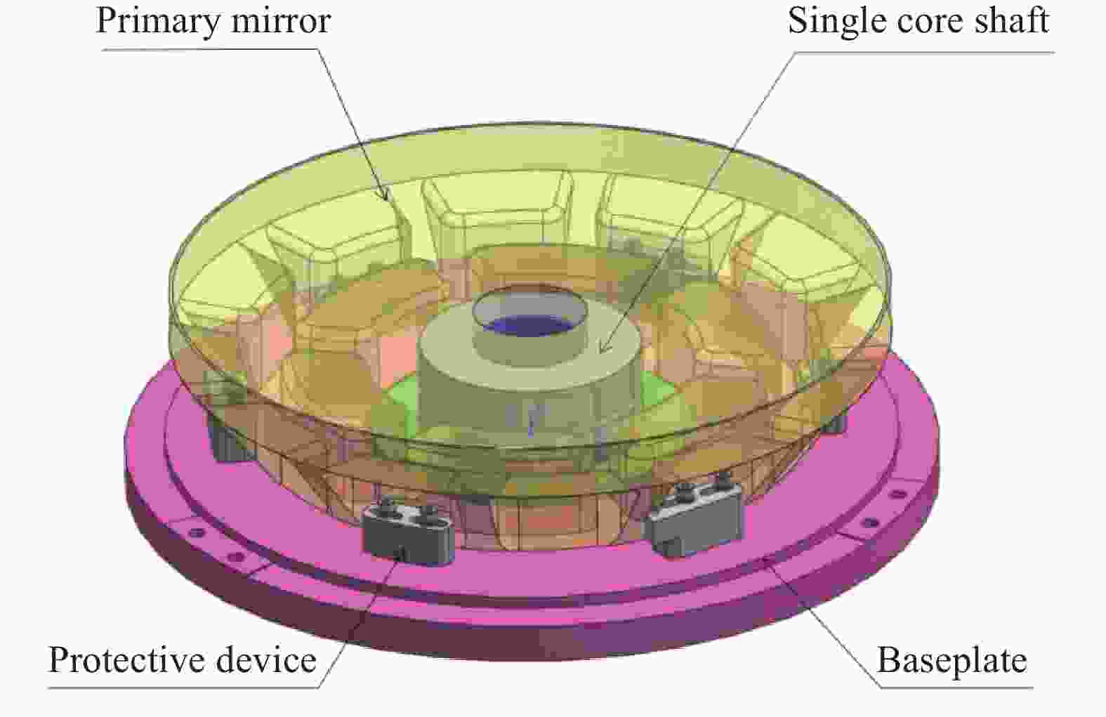
图 1 主系统组成结构
Figure 1. Main system structural composition
主镜通光口径为Ф350 mm,材料为肖特微晶玻璃(Schott Zerodur-M),芯轴底板及防护装置均为4J32。主镜与芯轴通过光学胶粘接,芯轴底板三点采用螺钉紧固进行刚性连接。各材料性能指标见表1。为满足光学成像系统的高精度要求,对主镜面形精度的要求设定为RMS≤35 mm、PV≤140 mm、RD≤6 µm。
表 1 材料力学特性
Table 1. Properties of the material mechanics
Material Density/
kg·m−3Elasticity/
GPaPoisson’s ratio Coefficient of
expansion/°C−1Schott Zerodur-M 2.7×10³ 91 0.24 0.01×10⁻⁶ 4J32 8.1×10³ 130 0.25 0.017×10⁻⁶ -
作为连接主镜的关键部件,芯轴的设计尤为重要。芯轴的作用主要是为主镜提供径向/轴向支持力,降低主镜在工作过程中各个姿态下光轴的晃动,确保主镜光轴指向的精准,并且与底板连接形成单芯轴支撑的统一整体,如图2所示。除了需要具备较好的支撑刚度,还需要一定的柔度用来吸收温差造成的热应力,支撑系统需在传导链c(底板)-a(法兰)-b(轴壁)-镜面中阻止底板变形产生的应力传递到主镜镜面上,合理的结构参数可以制造一定的柔度来吸收热应力。
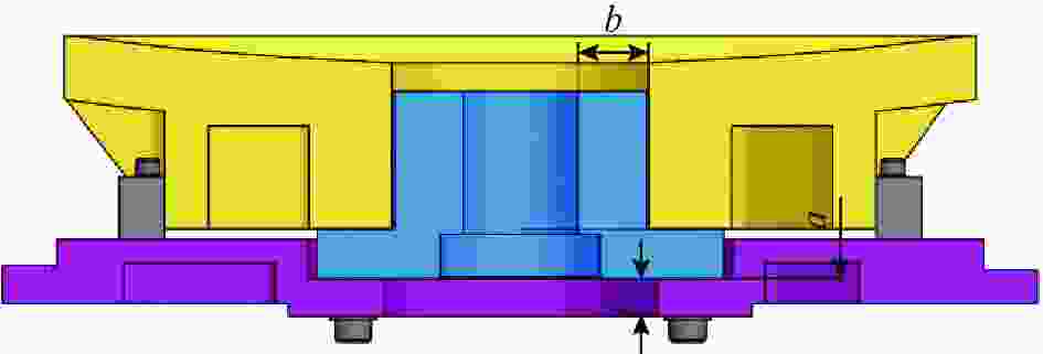
图 2 支撑结构各参数示意图
Figure 2. Schematic diagram of supporting structure parameters
为确保主镜在大温差工况下的面形精度,将研究重点放在优化结构参数以平衡支撑刚度和系统的柔度。合理设计的参数将在应力传递链路中有效阻断热应力,使系统能够吸收这些应力,从而维持主镜的面形精准度。
-
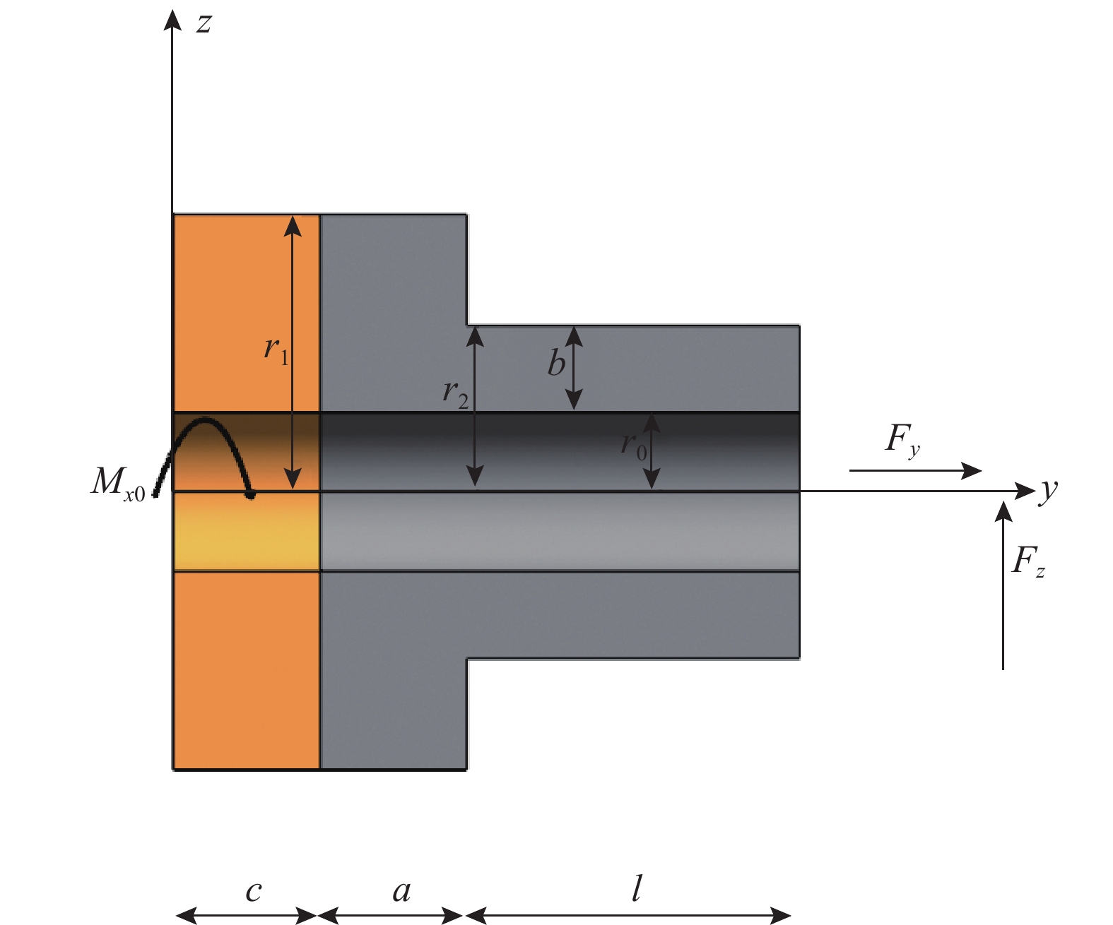
将底板、芯轴视为悬臂梁结构,以光轴水平状态(最大变形状态)为例,如图3所示。

图 3 支撑结构示意图
Figure 3. Schematic diagram of support structure diagram
图3中,r1为底板、法兰的直径,r2为芯轴外径,r0为芯轴内径,a为法兰厚度,b为轴壁厚度,c为底板厚度,l为芯轴轴长。
在y-z平面内,梁结构右端的变形量与载荷的关系为:
$$ \left\{ {\begin{array}{*{20}{c}} {{\theta _{{x}}}} \\ {{z}} \\ {{y}} \end{array}} \right\} = \left[ {\begin{array}{*{20}{c}} {{C_{11}}}&{{C_{12}}}&0 \\ {{C_{21}}}&{{C_{22}}}&0 \\ 0&0&{{C_{33}}} \end{array}} \right]\left\{ {\begin{array}{*{20}{c}} {{M_{{{x}}0}}} \\ {{F_{{z}}}} \\ {{F_{{y}}}} \end{array}} \right\} $$ (1) 式中:${\theta _{{x}}}$为芯轴在x轴上的角变位移量;z为z轴上的变形量;y为y轴上的变形量;${M_{{x}}}_0$为芯轴在x轴上的转矩;${F_{{z}}}$为芯轴在z轴上的受力;${F_{{y}}}$为芯轴在y轴上的受力;C11和C22代表对应方向上(θx 和z)的转角柔度;C12和C21为耦合系数,C12代表结构在θx方向上受到扭矩Mx0时,在z方向产生位移的柔度,C21代表结构在z方向上受到力Fz时,在θx方向产生转角的柔度;C33代表结构在y方向受到力Fy作用时,产生的位移与施加的力之间的比例关系。
根据互等定理,$ {C_{11}} $=$ {C_{12}} $,由卡式第二定理可得芯轴右端变形量为:
$$ \left\{ {\begin{array}{*{20}{c}} {{\theta _x} = \dfrac{{\partial U}}{{\partial {M_{x{\rm{0}}}}}}} \\ {y = \dfrac{{\partial U}}{{\partial {F_y}}}} \\ {z = \dfrac{{\partial U}}{{\partial {F_z}}}} \end{array}} \right. $$ (2) 由材料力学可知,轴端的变形能U为:
$$ U = \int\limits_c {\left( {\frac{{F_y^2\left( y \right)}}{{2E{A_1}}} + \frac{{M_x^2\left( y \right)}}{{2E{I_1}}}} \right)} {\rm{d}}y + $$ $$ \int\limits_a {\left( {\frac{{F_y^2\left( y \right)}}{{2E{A_1}}} + \frac{{M_z^2\left( y \right)}}{{2E{I_1}}}} \right)} {\rm{d}}y + \int\limits_l {\left( {\frac{{F_y^2\left( y \right)}}{{2E{A_2}}} + \frac{{M_z^2\left( y \right)}}{{2E{I_2}}}} \right)} {\rm{d}}y $$ (3) 式中:$E$为弹性模量; ${M_z} = {M_{z{\rm{0}}}} + {F_y}x$;A1为法兰和底板的截面积;A2为轴壁的截面面积; I1、I2为截面对x轴惯性矩。其中:
$$ {I_1} = \frac{{\pi \left( {{r_1}^4 - {r_0}^4} \right)}}{4} $$ (4) $$ {I_1} = \frac{{\pi \left( {{r_2}^4 - {r_0}^4} \right)}}{4} $$ (5) 将公式(2)~(5)代入公式(1)中,得到轴端转角柔度公式为:
$$ {C_{11}} = (a + c)\frac{4}{{E\pi \left[ {{r_1}^4 - {{\left( {{r_2} - b} \right)}^4}} \right]}} + l\frac{4}{{E\pi \left[ {r_2^4 - {{\left( {{r_2} - b} \right)}^4}} \right]}} $$ (6) 从上式可以看出,支撑结构柔度与E、r1、r2、l、a、b及c有关,其中E、r1、r2、l是定值(结构受次镜等影响)。通过软件绘制关系曲线来分析其关系,如图4所示。
从图4可以看出,随着法兰的厚度a及底板的厚度c增大,其柔度呈现上升趋势;反观轴壁的厚度b,其增加将导致柔度明显减少。在面临大的温差条件下,为确保在重力与由温度变化引发的应变的耦合效应中,主镜的面形精度维持在可接受的误差范围,选择合适的a、b和c参数至关重要。在实际操作中,主镜的表面精度(RMS、PV值)与其柔度具有高度关联性,更大的柔度可以更为高效地吸收由温差导致的材料膨胀应力,而高刚度有助于减少刚体的位移,从而确保光学系统对目标的精确指向。鉴于这种关系在真实系统中的固有复杂性,文中采用多岛遗传算法进行综合优化,旨在确保主镜处于最佳支撑状态。
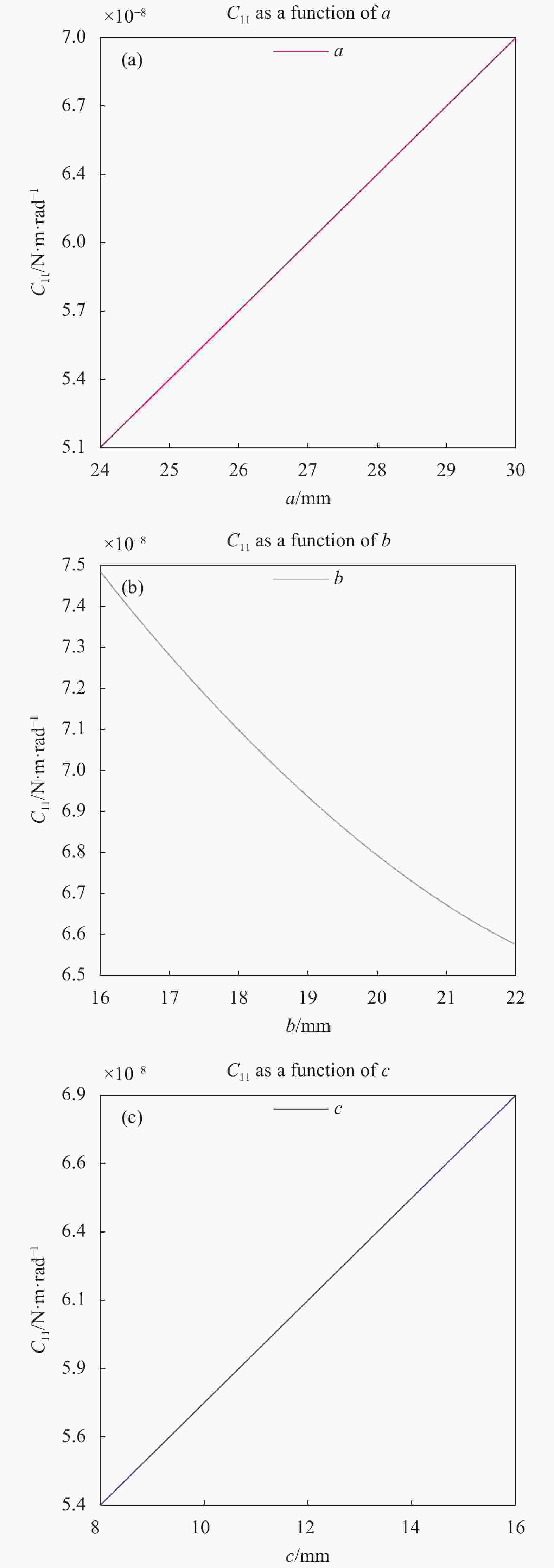
图 4 转角柔度C11和a、b、c的关系
Figure 4. Relationship between C11, a, b and c
-
优化算法的选择对于解决特定的工程问题至关重要。多岛遗传算法逐渐成为众多优化算法中的佼佼者。相较于传统遗传算法,它在全局搜索的能力和计算效率上都展现出明显的优势。这主要归因于其将总种群划分为若干子种群(或称“岛屿”)的独特策略,每个“岛屿”都执行传统遗传算法中的基本操作,选择、交叉和变异,如图5所示。利用该策略,算法能够在解的空间中进行高效编码,迭代地寻找最佳或近似最佳的解决方案。在支撑结构的优化问题中,目标是优化法兰a、轴壁b以及底板c,以使得主镜面的面形误差RMS、PV和RD达到最优值。
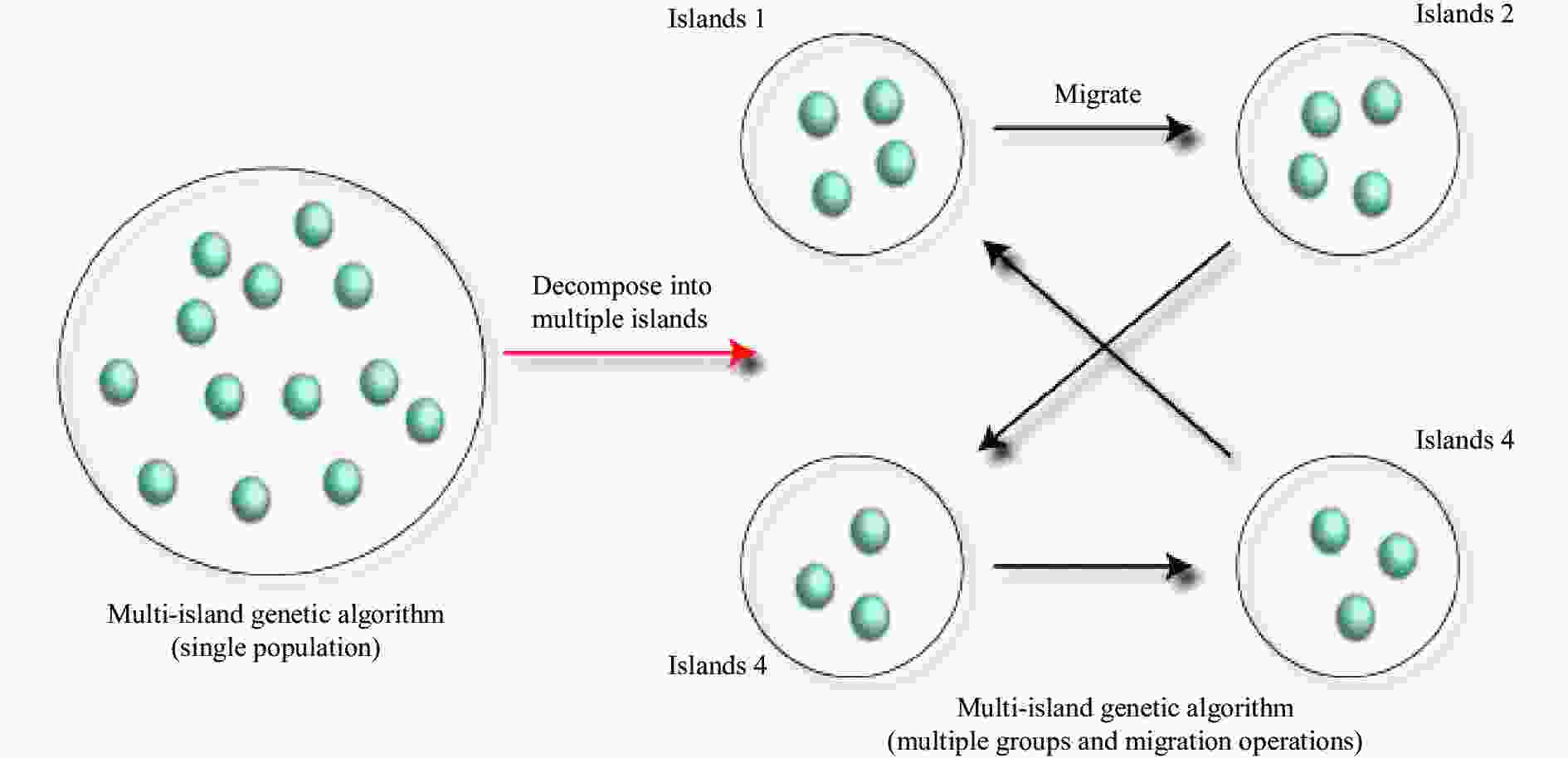
图 5 多岛遗传算法示意图
Figure 5. Structure of MISA
多岛遗传算法中共有10个可调参数,分为七个高级条件和三个基本条件。其中,岛数(Number of islands)设置为10以增强种群多样性并促进岛屿间的独立进化,从而提高探索整个解空间的能力。子种群规模(Sub-population size)也为10,使得总种群大小达到100,为每次迭代提供100种可能的解。这种设置在维持多样性的同时不会损害计算效率。迁移间隔(Interval of migration )为 10,均衡了种群多样性与信息交换的频率,防止种群过早汇聚或岛屿间孤立。最后,1000次的总迭代确保了算法有充分时间探索解空间,每10次迭代进行的迁移则确保了在1000次迭代中有100次迁移机会,加强了信息交换。简而言之,这些参数的选择旨在实现多样性、算法效率与解质量之间的平衡,具体参数设置如表2所示。
表 2 多岛遗传算法参数设置
Table 2. MIGA parameter setting
Parameter Value Sub-population size 10 Rate of mutation 0.01 Number of islands 10 Rate of migration 0.01 Number of generations 10 Interval of migration 10 Crossover probability 0.99 基于以往类似的工程经验,文中模型的柔节初始值a=27 mm,b=17 mm,c=9 mm。在优化之前,需要对相关变量进行约束,只有约束条件成立,相关的优化结果才有意义。支撑结构中的参数根据实际工程经验选取,约束条件如下:
$$ {\mathrm{Minimum}}\qquad\qquad {{RMS}}=F( a,b,c ) $$ (7) $$ PV=G( a,b,c ) $$ (8) $$ RD=H( a,b,c ) $$ (9) $$ {\mathrm{subject}}\;\; {\mathrm{to}}\;\; 24\;{\mathrm{mm}} \leqslant a\leqslant 30\;{\mathrm{mm }}$$ (10) $$ 16\;{\mathrm{mm}} \leqslant b \leqslant 22\;{\mathrm{mm}} $$ (11) $$ 8\;{\mathrm{mm}} \leqslant c \leqslant 16\; {\mathrm{mm }} $$ (12) -
Isight集成平台是光机集成优化领域最成熟的平台之一,能够简单、有效地实现多学科软件(如光学误差计算和有限元分析)与自动化过程的集成,具体工作流程如图6所示。首先,通过UG对三维模型进行参数化建模并采用粗大网格划分,可以有效节省计算时间,同时完成属性设置和约束定义以生成有限元模型。随后,利用录制宏程序和生成循环脚本实现自动化流程,以20 ℃温差和主镜光轴水平为工况生成sim文件做有限元分析。之后,将有限元分析云图中的镜面节点数据以文本形式导入到软件中,通过自编程序计算RMS、PV、RD的数值。最终,通过在Isight的optimization模块中使用多岛遗传算法进行循环迭代,并在全局搜索中成功确定最佳数据点。

图 6 Isight集成平台工作流程图
Figure 6. Workflow chart of Isight integration platform
-
多岛遗传算法经过1000次迭代,得到了a、b、c、PV、RMS和RD的迭代历程。图7(a)~(c)所示分别为RMS、PV和RD的迭代过程。由于其复杂的非线性、多模态性质、高维度设计空间以及参数之间的耦合性,光机结构优化在这种环境下变得难以收敛到一个稳定值。

图 7 多岛遗传算法的迭代过程
Figure 7. Iterative processes of MIGA

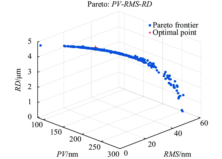
图 8 Pareto前沿分析参数之间的关系
Figure 8. Pareto front analysis of parameter relationships
为了进一步分析参数之间的关系,文中采用Pareto前沿的方法。如图8所示,通过Pareto前沿的分析,发现RMS与PV之间呈正相关,而与RD呈负相关,与前文的分析一致。
通过多岛遗传算法,在Pareto前沿分析中,图8中红色五角星标注的数据点(第836代数据点)在a、b、c参数上表现出色。该点在柔度和刚度上达到平衡,为地基光电成像系统在大温差下提供了刚柔并济的方案。如表3所示,其在PV、RMS和RD的优化率分别为68.43%、35.62%和35.47%。
表 3 优化前后对比
Table 3. Comparison before and after optimization
Parameter Before optimization After optimization Optimization rate a 25 mm 27.20 mm - b 17 mm 18.93 mm - c 9 mm 11.23 mm - RMS 56.7 nm 17.9 nm 68.43% PV 140.1 nm 90.2 nm 35.62% RD 6.54 µm 4.22 µm 35.47% -
在有限元分析之前,将Isight求得的最优解输入到几何模型中,然后对底板三个连接面的Z方向进行固定约束,在底板底面X轴选两点进行Y向约束,Y轴选两点进行X向约束,这样的约束设置更真实地模拟整个支撑结构受力,充分释放温差导致的变形量,得到更接近实际情况的结果。通过在软件中使用Zernike多项式进行拟合计算,得出主镜在−40~+40 ℃范围内的RMS值变化为16.52 nm,PV值为36.2 nm,均满足设计要求。变形云图如图9所示,可以看出,镜面应力分布比较均匀,确保了主镜的图像质量。
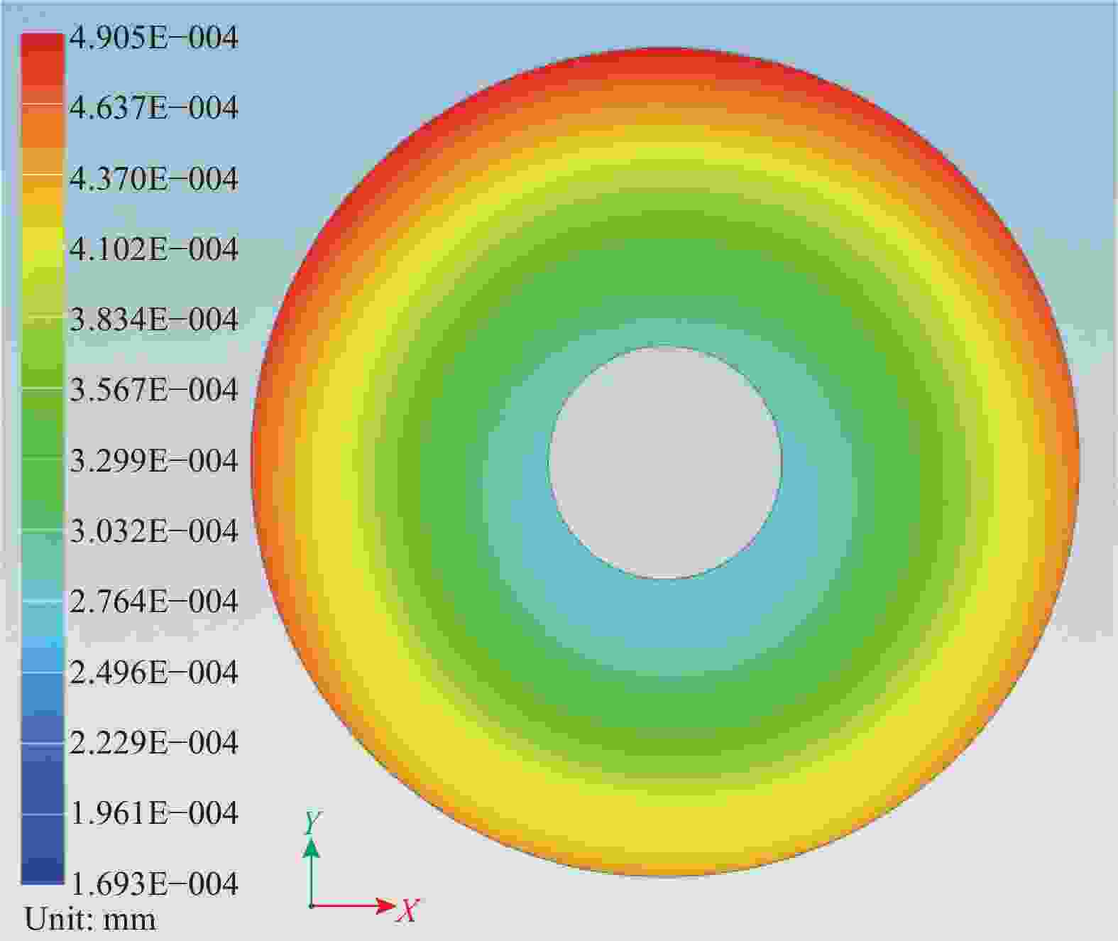
图 9 温度场下的主镜变形云图
Figure 9. Deformation cloud map of the primary mirror under thermal field
-
分析自重在光轴水平方向和竖直方向载荷作用下的主镜变形量,可以直接反映主镜支撑结构的支撑性能,分别对这两种工况下的主镜进行静力学分析,最大变形云图(光轴水平状态)如图10所示。计算得出光轴竖直时刚体位移为2.19 μm,光轴水平时刚体位移为4.19 μm,与未作优化时光轴竖直工况下刚体位移为3.08 μm、光轴水平工况下位移为6.51 μm相比,优化率分别可达20.9%和35.64%,均满足设计要求。

图 10 重力场下的主镜变形云图
Figure 10. Deformation cloud map of the primary mirror under gravitational field
-
在实际工作状态下,主镜既受到重力的影响,又受到热载荷的作用。确定了柔性支撑参数后,文中对整个结构进行了充分分析。首先,考虑温度差ΔT=20 ℃(模拟试验环境下的温度变化范围,+20 ~+40 ℃)及光轴在水平和竖直方向上的重力作用,以评估在这一温度下主镜的综合面形误差。接下来,分析温度差ΔT=20 ℃(模拟实际环境下的温度变化范围,即−40~+40 ℃)及光轴在水平和竖直方向上的重力作用下的主镜综合面形误差。这种分析方法更为真实地模拟了支撑结构的力学性能,相关的分析结果如表4所示。
表 4 主镜各工作状态误差
Table 4. Each working state error of the primary mirror
Load RMS/nm PV/nm RD/μm G光轴竖直,ΔT=20 ℃ 10.53 71.06 2.21 G光轴水平,ΔT=20 ℃ 17.84 90.33 4.23 G光轴竖直,ΔT=80 ℃ 20.46 90.17 2.32 G光轴水平,ΔT=80 ℃ 27.06 115.64 4.29 在力热耦合极端情况下(ΔT=80 ℃),主镜综合面形误差RMS均小于40 nm,PV值小于170 nm,满足光学成像要求。
-
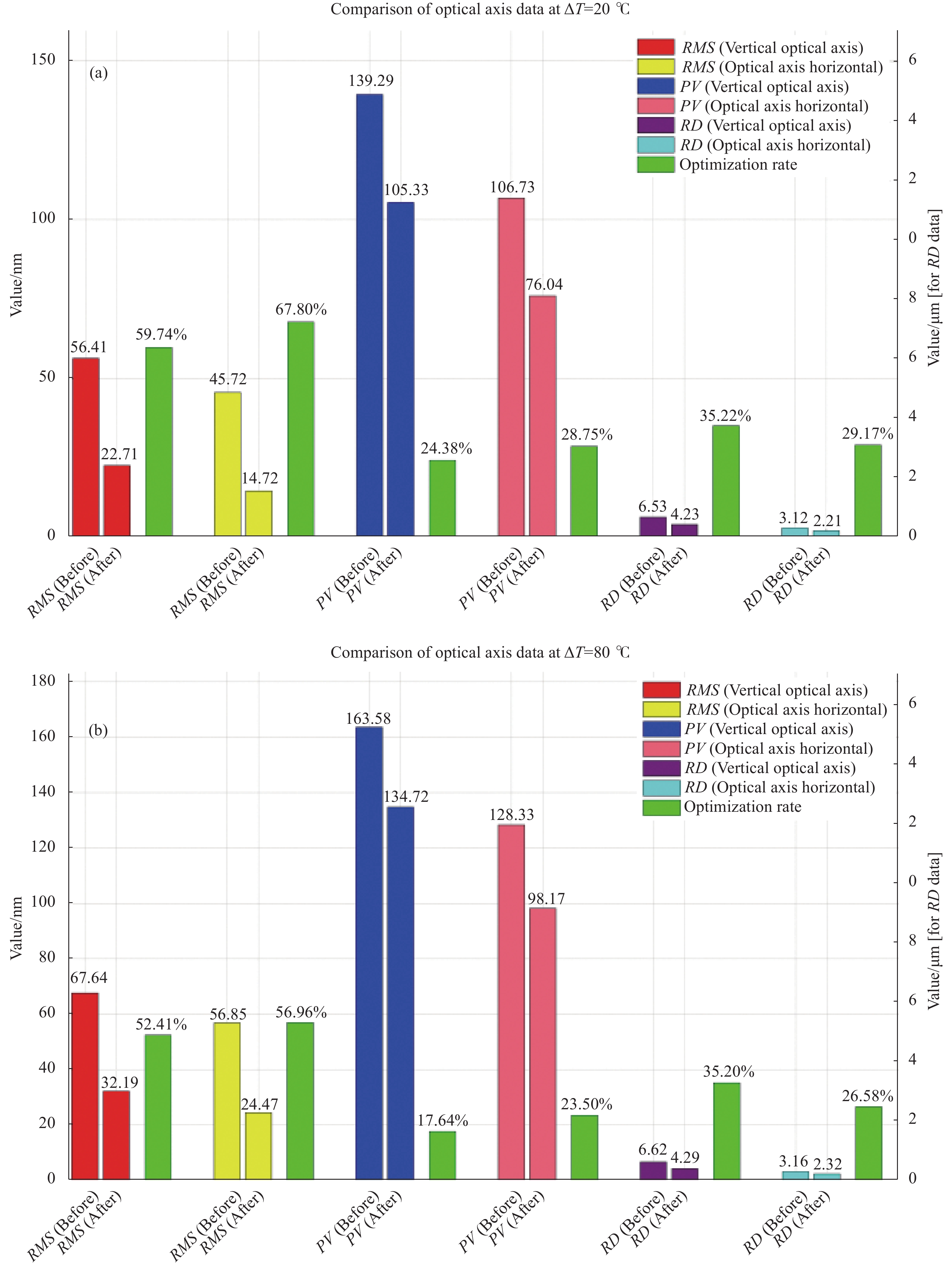
图11所示为优化前后系统在两种力热偶合工况下对主镜面形精度的影响。其中,RMS (Before)、PV (Before)和RD (Before)代表原始模型数据,RMS (After)、PV (After)和RD (After)为优化后数据。

图 11 不同温度变化下优化前后的表面形状误差整体比较。(a) ΔT=20 ℃ (+20~+40 ℃);(b) ΔT=80 ℃ (−40~+40 ℃)
Figure 11. Overall comparison of surface shape errors before and after optimization under different temperature changes. (a) ΔT=20 ℃ (from +20 ℃ to +40 ℃); (b) ΔT=80 ℃ (from −40 ℃ to +40 ℃)
优化后的数据显示,各项指标均得到了改进,特别是在温差ΔT=80 ℃(Optical axis horizontal)的工况下,RMS和PV的优化率达到了59.99%和23.2%。
-
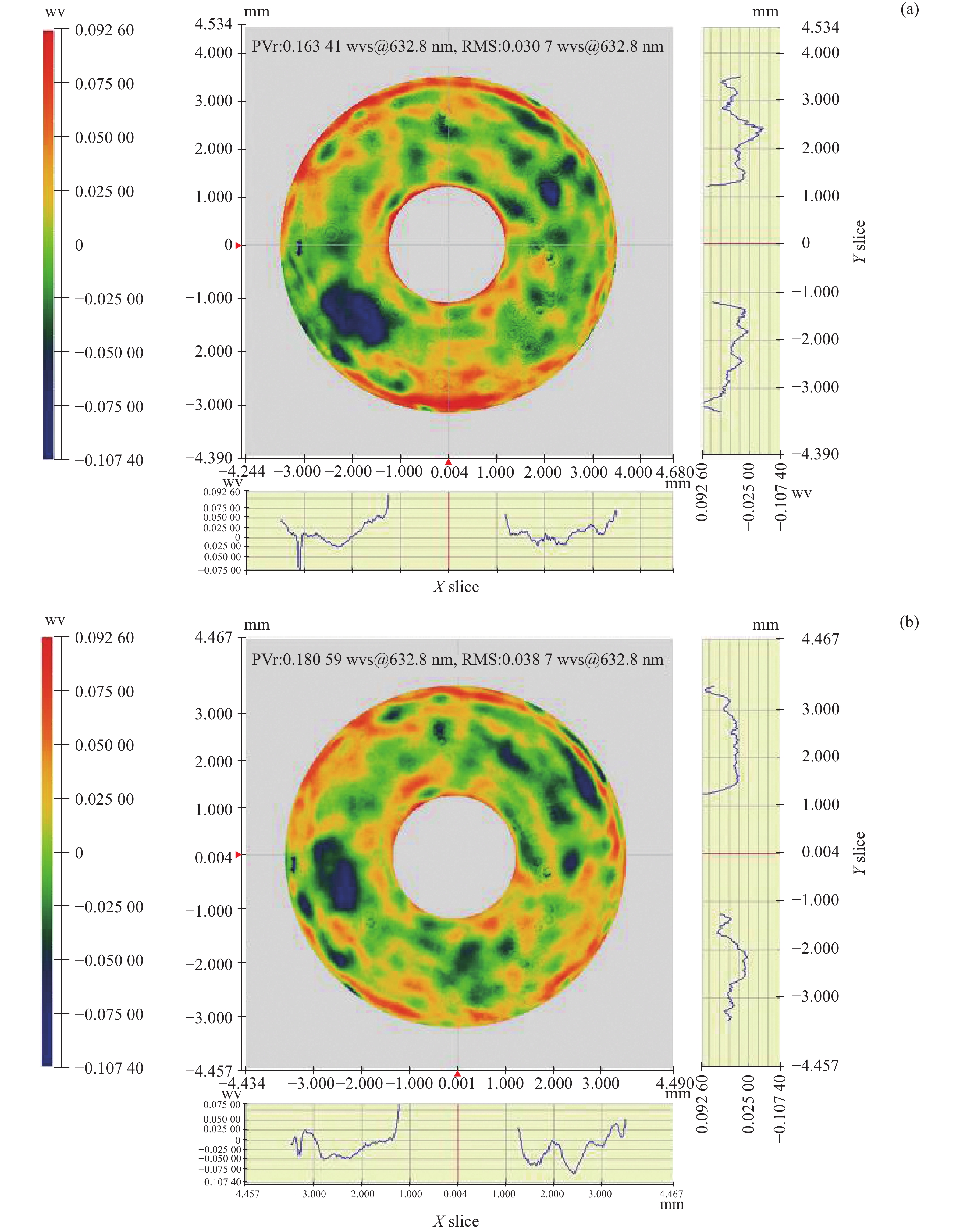
根据上述方案完成支撑结构的加工制造并装配到光学系统中。裸镜面形精度RMS=4.4 nm、PV=56.28 nm,其中变形误差主要由加工误差和重力载荷引起。将主镜精密装配并确保其位于光轴水平状态(该状态下引起的镜面变形最大),如图12所示。
主镜的面形精度检测在室温20 ℃的条件下开始,随后升温至40 ℃。这两个温度点的选择是基于实验条件的限制:实验室设备和环境能够可靠地模拟这一温度范围内的变化。虽然这两个温度点不代表极端条件,但它们提供了一个实用的框架来评估材料和结构在常见工作温度下的性能。在20 ℃和40 ℃条件下,RMS值分别为15.81 nm和19.23 nm,PV值分别为83.17 nm和91.98 nm。20 ℃的温差导致的面形误差RMS为3.42 nm、PV为8.81 nm,干涉图如图13所示。基于温度载荷与面形误差之间的近似线性关系,推断在更广泛的温差范围内,如−40~+40 ℃的80 ℃温差下,主镜的面形误差RMS约为10.3 nm,PV的峰值误差约为26.5 nm,这些误差值均在光学成像系统的可接受范围内。
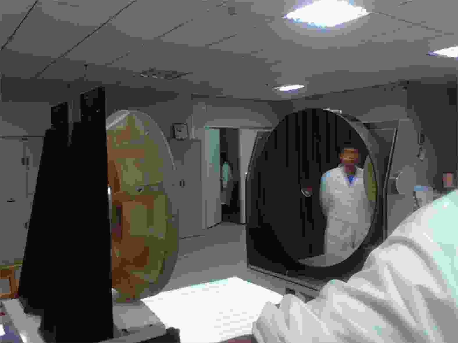
图 12 主镜置于在光轴水平位置
Figure 12. The primary mirror is placed in a horizontal position along the optical axis

图 13 激光干涉仪对主镜面形精度检测。 (a) 20 ℃下的检测;(b) 40 ℃下的检测
Figure 13. Analysis of main mirror surface accuracy using interferometry. (a) Detection at 20 ℃; (b) Detection at 40 ℃
-
文中聚焦于中口径地基光电成像装备在极端温差环境下的支撑结构设计方法,并进行了全面深入的分析和优化。考虑在大温差和大俯仰角的工作条件下,采用单芯轴支撑结构,有效地减轻了温差引起的热应变效应,同时保持刚体位移在合理范围内,并通过卡式第二定理,深入分析了芯轴和底板的结构参数。之后通过多岛遗传算法对轴壁、法兰和底板厚度进行多目标优化,以同时满足系统的使用要求。通过仿真验证,证明了在不同工况下,主镜的面形误差均满足光学成像的要求。最后,通过实物试验,进一步验证了所设计结构的有效性。在ΔT=80 ℃、主镜光轴水平状态下,RMS和PV的优化率分别达到了59.99%和23.2%,同时刚体位移的优化率高达21.96%,主镜的面形精度也得到了令人满意的改善。
未来工作将探讨单芯轴结构在更广泛的温差和更大口径主镜下的应用可能性,以及进一步优化和实验验证其光学性能和结构稳定性。该研究不仅为当前的地基光电成像系统设计提供了重要的参考和实践经验,而且为未来类似系统的发展奠定了基础。
Design and optimization of a single-core axis in a ground-based photoelectric imaging system
-
摘要: 在大俯仰角和极端温差条件下,保持地基光电成像系统主镜面形精度的稳定性是关键。文中提出了一种新型单芯轴支撑结构,旨在提高主镜在极端环境下的稳定性和热膨胀适应能力,从而保证面形精度。通过卡式第二定理深入分析单芯轴应力尺寸链参数对镜面误差的影响,并结合Isight平台和多岛遗传算法进行结构参数优化,实现了结构稳定性与面形精度的平衡。仿真结果表明,在不同环境条件下,主镜的均方根波前误差(RMS)均小于30 nm,峰值差(PV)小于120 nm,满足光学成像的高标准要求。此外,在ΔT=80 ℃、主镜光轴水平状态下,RMS和PV的优化率分别达到59.99%和23.2%,刚体位移的优化率高达21.96%,体现了设计的高效性。在20 ℃和40 ℃的控制室温条件下进行的激光干涉仪测试进一步证实了设计的有效性,以及与仿真结果的高度一致性。该研究为在大温差、大俯仰角条件下的地基光电成像系统中,中口径主镜的支撑结构设计提供了有力的参考,特别是在提高主镜面形精度方面具有重要意义。未来的研究将探讨该结构在更广泛温差和更大口径主镜下的应用,以及进一步优化其光学性能和结构稳定性。Abstract:
Objective The study aims at addressing a critical need in ground-based optoelectronic imaging, which is enhancing the surface form accuracy of primary mirrors under extreme conditions such as large pitch angles and significant temperature variations. This aim is vital as it directly impacts on the quality of optical imaging, an increasingly important factor in various applications ranging from scientific research to defense. Recognizing the limitations of traditional support structures in these challenging environments, a novel monolithic shaft support structure was developed in this paper. This new design was targeted to significantly improve the stability and thermal adaptability of primary mirrors, ensuring their performance in demanding conditions. The study involved rigorous theoretical analysis using Castigliano's second theorem and practical optimization using advanced techniques like the multi-island genetic algorithm. These methods were integral to balancing structural stability with precise surface form accuracy, setting a new benchmark in the field. In essence, this research sought to revolutionize the design and functionality of support structures for medium-caliber primary mirrors in ground-based optoelectronic systems, enhancing their reliability and performance in extreme environments. This advancement was not just an improvement but a necessary step to meet the growing demands for high-quality optical imaging in diverse and challenging conditions. Methods A novel single-core-axis support structure was proposed to enhance the mirror's stability and adaptability to thermal expansion. The study utilized Castigliano's second theorem for an in-depth analysis of the impact of the single-core-axis stress size chain parameters on the mirror surface errors. Further, an integration of Isight platform and a multi-island genetic algorithm was employed for optimizing the structural parameters. This approach allowed for a fine-tuned balance between structural stability and surface accuracy. Results and Discussions In this study, the fabricated support structure was integrated into the optical system, achieving a primary mirror surface precision with an RMS of 4.4 nm and a PV of 56.28 nm, primarily affected by manufacturing errors and gravitational load. The mirror was positioned horizontally along the optical axis to induce maximal surface deformation (Fig.12). Surface accuracy assessments at room temperatures of 20 ℃ and 40 ℃ revealed RMS values of 15.81 nm and 19.23 nm, and PV values of 83.17 nm and 91.98 nm, respectively. The 20 ℃ temperature variation introduced a form error RMS of 3.42 nm and a PV of 8.81 nm (Fig.13). Extrapolating from these results, under an extended temperature range (−40 ℃ to +40 ℃), the estimated RMS and PV errors are approximately 10.3 nm and 26.5 nm, respectively, well within acceptable limits for optical imaging systems. These findings, validated through interferometric analysis (Fig.13), demonstrate the design's capability to maintain mirror surface accuracy under varied temperature conditions, confirming its suitability for diverse environmental applications. Conclusions This research addressed the design of support structures for medium-caliber ground-based optoelectronic imaging equipment in extreme temperature differential environments. The monolithic shaft support structure adopted significantly reduced thermal strain and maintained rigid body displacement within acceptable limits. Key structural parameters were analyzed using Castigliano's second theorem, and a multi-island genetic algorithm was employed for multi-objective optimization of structural components. Simulation and physical experiments validated that the primary mirror's surface form error adhered to optical imaging requirements even under significant temperature variations (ΔT=80 ℃). Notably, the optimization of RMS and PV values improved by 59.99% and 23.2%, respectively, with a 21.96% enhancement in rigid body displacement. Future work will focus on extending the application of the monolithic shaft structure to larger aperture mirrors and broader temperature ranges, further optimizing and validating its optical and structural stability. This study provides essential insights for the development of ground-based optoelectronic imaging systems. -
图 9 温度场下的主镜变形云图
Figure 9. Deformation cloud map of the primary mirror under thermal field
图 10 重力场下的主镜变形云图
Figure 10. Deformation cloud map of the primary mirror under gravitational field
图 11 不同温度变化下优化前后的表面形状误差整体比较。(a) ΔT=20 ℃ (+20~+40 ℃);(b) ΔT=80 ℃ (−40~+40 ℃)
Figure 11. Overall comparison of surface shape errors before and after optimization under different temperature changes. (a) ΔT=20 ℃ (from +20 ℃ to +40 ℃); (b) ΔT=80 ℃ (from −40 ℃ to +40 ℃)
图 12 主镜置于在光轴水平位置
Figure 12. The primary mirror is placed in a horizontal position along the optical axis
图 13 激光干涉仪对主镜面形精度检测。 (a) 20 ℃下的检测;(b) 40 ℃下的检测
Figure 13. Analysis of main mirror surface accuracy using interferometry. (a) Detection at 20 ℃; (b) Detection at 40 ℃
表 1 材料力学特性
Table 1. Properties of the material mechanics
Material Density/
kg·m−3Elasticity/
GPaPoisson’s ratio Coefficient of
expansion/°C−1Schott Zerodur-M 2.7×10³ 91 0.24 0.01×10⁻⁶ 4J32 8.1×10³ 130 0.25 0.017×10⁻⁶  下载: 导出CSV
表 2 多岛遗传算法参数设置
Table 2. MIGA parameter setting
Parameter Value Sub-population size 10 Rate of mutation 0.01 Number of islands 10 Rate of migration 0.01 Number of generations 10 Interval of migration 10 Crossover probability 0.99
下载: 导出CSV
表 3 优化前后对比
Table 3. Comparison before and after optimization
Parameter Before optimization After optimization Optimization rate a 25 mm 27.20 mm - b 17 mm 18.93 mm - c 9 mm 11.23 mm - RMS 56.7 nm 17.9 nm 68.43% PV 140.1 nm 90.2 nm 35.62% RD 6.54 µm 4.22 µm 35.47%
下载: 导出CSV
表 4 主镜各工作状态误差
Table 4. Each working state error of the primary mirror
Load RMS/nm PV/nm RD/μm G光轴竖直,ΔT=20 ℃ 10.53 71.06 2.21 G光轴水平,ΔT=20 ℃ 17.84 90.33 4.23 G光轴竖直,ΔT=80 ℃ 20.46 90.17 2.32 G光轴水平,ΔT=80 ℃ 27.06 115.64 4.29
下载: 导出CSV
-
[1] Yan P, Yang Y, She W, et al. Wide-field and large aperture optical system design for ground-based photoelectric detection [C]//9th International Symposium on Advanced Optical Manufacturing and Testing Technologies: Large Mirrors and Telescopes, 2019, 10837: 230-236. [2] Chen J Q. Principle and Design of Astronomical Telescopes[M]. Nanjing: Nanjing University Press, 2020. [3] Cheng X, Liu C. Optical and mechanical performance and feasibility analysis of meter-level corrector lenses for survey telescope [J]. Photonics, 2023, 10(4): 422. doi: 10.3390/photonics10040422 [4] Shao M, Zhang L, Jia X. Optomechanical integrated optimization of a lightweight mirror for space cameras [J]. Appl Opt, 2021, 60(3): 539-546. doi: 10.1364/AO.409658 [5] Ma D. Recommended conceptual optical system design for China’s large optical-infrared telescope (LOT) [J]. Opt Express, 2018, 26(1): 108-119. doi: 10.1364/OE.26.000108 [6] Peng Y L, Dai Y F, Chen S Y. Research on the support and gravitational deformation of large aperture primary mirror of space telescopes [J]. Key Eng Mater, 2012, 516: 181-185. doi: 10.4028/www.scientific.net/KEM.516.181 [7] Laslandes M, Hugot E, Ferrari M, et al. Space Active Optics: toward optimized correcting mirrors for future large spaceborne observatories [C]//Optical Design and Engineering IV, 2011, 8167: 320-328. [8] Kihm H, Yang H S, Moon I K, et al. Adjustable bipod flexures for mounting mirrors in a space telescope [J]. Appl Opt, 2012, 51(32): 7776-7783. doi: 10.1364/AO.51.007776 [9] Wei L, Zhang L, Gong X, et al. Design and optimization for main support structure of a large-area off-axis three-mirror space camera [J]. Appl Opt, 2017, 56(4): 1094-1100. doi: 10.1364/ao.56.001094 [10] Lu R, Yuan J, Wei G, et al. Optimization design of energy-saving mixed flow pump based on MIGA-RBF algorithm [J]. Machines, 2021, 9(12): 365. doi: 10.3390/machines9120365 [11] Liu Q, Wang S X, Tian F X, et al. Research on integrated design method of high-precision space-based active optical large-caliber splicing mirror drive and support [J]. Optik, 2020, 204: 163849. doi: 10.1016/j.ijleo.2019.163849 [12] Huo T, Yu J, Zhao H. Design of a kinematic flexure mount for precision instruments based on stiffness characteristics of flexural pivot [J]. Mech Mach Theory, 2020, 150: 103868. doi: 10.1016/j.mechmachtheory.2020.103868 [13] Wang Y, Wang P, Zhang S. Research and design of kinematic support flexibility for metal mirror [J]. Optik, 2021, 241: 166386. doi: 10.1016/j.ijleo.2021.166386 [14] Liu Q, Zhou L J, Bao H, et al. Design and analysis of three-dimensional compliant structure suitable for integrated design of support and drive of space optical mirror [J]. Optik, 2021, 225: 165757. doi: 10.1016/j.ijleo.2020.165757 [15] Jin Z, Cheng G, Pang Y, et al. Multi-objective parameter optimization of flexible support system of optical mirror [J]. Appl Sci, 2021, 11(17): 8071. doi: 10.3390/app11178071 [16] Rios L M, Sahinidis N V. Derivative-free optimization: a review of algorithms and comparison of software implementations [J]. J Glob Optim, 2013, 56: 1247-1293. doi: 10.1007/s10898-012-9951-y [17] Dai X, Xian H, Tang J, et al. Modification of the support and active correction method for an experimental thin primary mirror [J]. J Mod Optic, 2019, 66(18): 1841-1849. doi: 10.1080/09500340.2019.1682701 [18] Song B, Lyu D, Jiang J. Optimization of composite ring stiffened cylindrical hulls for unmanned underwater vehicles using multi-island genetic algorithm [J]. J Reinf Plast Comp, 2018, 37(10): 668-684. doi: 10.1177/0731684418760203 [19] Zhang Z, Wu B, Wu L, et al. Optimization of the bionic wing shape of tidal turbines using multi-island genetic algorithm [J]. Machines, 2022, 11(1): 43. doi: 10.3390/machines11010043 [20] Liu S, Zheng K, Li H, et al. Multi-objective optimization of process parameters in longitudinal-torsional ultrasonic vibration face grinding CFRP [J]. Machines, 2023, 11(10): 935. doi: 10.3390/machines11100935 -

 点击查看大图

计量
- 文章访问数: 31
- HTML全文浏览量: 1
- PDF下载量: 24
- 被引次数: 0

