


 下载:
下载:


-
无线激光通信技术具有通信速率高、保密性好和轻便灵活等优点,在军事和民用通信领域都具有广阔的应用前景,受到广泛关注。飞机作为无线激光通信研究中的重要搭载平台之一,可以有效提高激光通信的可通性和适用范围,在未来空天地一体化网络中扮演者重要的角色。但机载激光通信在迈向应用的过程中还面临着许多困难,除了存在大气吸收、散射、平台振动、云层遮挡等大气激光通信常面临的共性问题外,气动光学效应也是制约机载激光通信应用重要因素之一[1−3]。
20世纪80年代,美国超高音速导弹性能评估中心(HIPEC)自主研发出一套气动光学效应分析软件,能够针对外冷绕流场进行仿真分析,可以对气动效应所带来的成像损失程度进行分析和预测[4]。21世纪初,美国圣母大学设计了一套光学测量装备,并进行了亚音速风洞试验,针对低速流场气动光学效应建立了自适应矫正系统,对简单二维热射流采用前向反馈系统,将成像时均质量提升38%[5]。2011年,由美国 Notre Dame大学机载气动光学实验室(AAOL)开展的跨音速平面窗口转台气动光学试验,重点研究了高速飞行条件下,外挂吊舱平面窗口的气动光学效应[6]。2012年,美国导弹防御局(MDA)将机载激光武器系统ABL(Airborne Laser)安装在一架改进型波音747飞机上。科研人员对其光学系统所在的凸台及锥形结构部分进行了流场分析与优化。以保证流动的均匀性,以减小气动光学效应对激光传能的影响[7]。
自进入21世纪以来,国内对气动光学的研究逐渐兴起。2003年殷兴良出版的《气动光学原理》一书奠定了我国气动光学的基础[8]。李桂春在其著作《气动光学》一书中对气动光学原理和实验测量方法进行了详细论述[9]。孟立新等根据试验中大气附面层引起的接收光斑离焦现象,进行了气动光学仿真,设计了补偿手段,并进行了飞行试验,使接收光斑离焦现象得到了抑制,接收光功率闪烁方差减小了1/3[10]。丁浩林等对超声速湍流边界层的气动光学效应开展了风洞实验研究,并开展了带超声速气膜的高超声速光学头罩的气动光学效应抑制实验[11]。赵鑫海等针对射流折射率场的非均匀分布导致成像质量降低的问题,在真空实验舱内研究了不同总压条件下超声速半自由射流的光程差(OPD)分布,推导了OPD沿流向分布的经验公式[12]。谭小童等通过Zernike多项式拟合波前,分析了典型光学窗口排除自适应光学之外的高阶气动光学效应,并对两种窗口进行了比对[13]。董航等对圆柱半球转塔模型进行了气动光学效应时空特性分析[14]。这些研究为我国气动光学领域的发展提供了重要的理论基础和实验支持,同时也为改善光学系统在复杂气动环境下的性能提供了有益的经验和方法。
上述学者在气动光学领域提供了重要的研究成果,但有关气动光学对机载激光通方面的研究相对较少。其中,远场光斑峰值光强和光斑偏移量是机载激光通信中的两个重要指标;光强衰减会导致接收光功率闪烁方差加大,增大通信误码率;光斑偏移会降低激光通信跟踪系统精度。文中重点分析了不同窗口形态在不同转角、飞行速度、飞行高度下对远场光斑光强和偏移量的影响规律,分析更为全面,为机载激光通信系统设计与优化提供参考。
-
机载激光通信光端机的光机结构如图1所示,主要由光学基台和稳瞄转台两部分组成。稳瞄转台包括整流罩、跟踪框架、反射镜组件和光学天线,而光学基台由支撑板和子光路组成,整体通过支撑板吊装在飞机下部。稳瞄转台采用单反射镜式,优点在于光学天线、子光路、探测器、激光器等核心元件不需要因为视轴方向的调整而移动,运动负载仅包括反射镜组件,其转动惯量较小,提高了系统的可靠性和伺服带宽。

图 1 机载激光通信光端机整体结构
Figure 1. Overall structure of airborne laser communication optical terminal
具体参数方面,俯仰运动范围为−10°~+5°(光束伺服角度为−20°~+10°),方位运动范围为±180°,有效光学口径为$\phi $86 mm,外形包络尺寸为$\phi $214 mm×199 mm。拟搭载于Y-12等中低速飞机。
光端机的光路结构如图2所示。通信光和信标光分别采用1550 nm和800 nm波段的激光,在进行光束接收时,激光束首先进入指向反射镜组件,通过平面反射镜反射,进入光学天线进行缩束后传递至子光路单元。子光路单元通过分光镜实现对不同波长光束的折转,将通信光汇聚至探测器,同时将信标光汇聚到跟踪相机。在发射光束时,光路原理与接收时相同,但路径相反。

图 2 机载激光通信光端机光路示意图
Figure 2. Schematic diagram of the optical path in the airborne laser communication optical terminal
-
为了研究光端机附近的流场情况,文中选取了带有共形和平面两种常用光学窗口的整流罩,对比两者在不同参数下的气动光学效应。整流罩的几何模型如图3所示,其中R=0.13 m,H=0.1104 m,L=0.102 m,光学窗口半径r=0.1105 m。
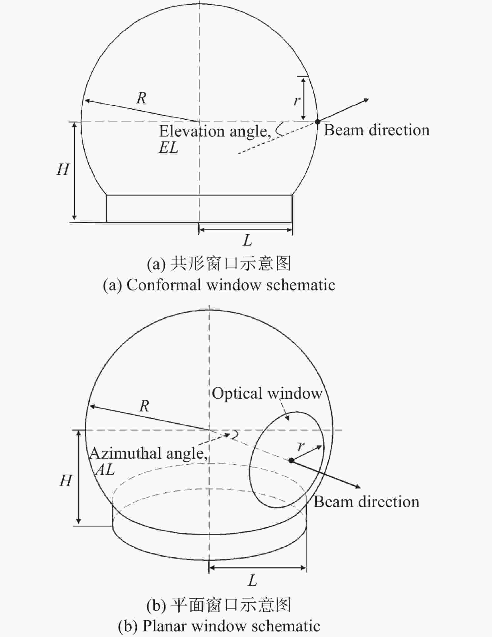
图 3 光学窗口几何模型示意图及视角定义
Figure 3. Geometric model schematic of the optical window and definition of viewing angles
合理的仿真区域和边界条件设置是流场仿真分析的关键,图4为了平面光学窗口方位转角90°的流场计算域和边界条件设置,整体流体域采用27.5R×12R×6R,其中光端机中心距离流场入口的距离为7.5R,采用速度入口边界条件,距离出口的距离为20R,采用静压出口边界条件,上表面及两侧面采用绝热自由滑移边界条件,而下表面和转塔表面则采用绝热无滑移边界条件。

图 4 计算域尺寸与边界设置
Figure 4. Calculation domain size and boundary settings
图5为两种窗口表面结构化面网格分布,为了提高模拟精度,对光学窗口周围的网格进行网格加密,共形光学窗口的网格量为1007777;平面光学窗口的网格量为1005263。
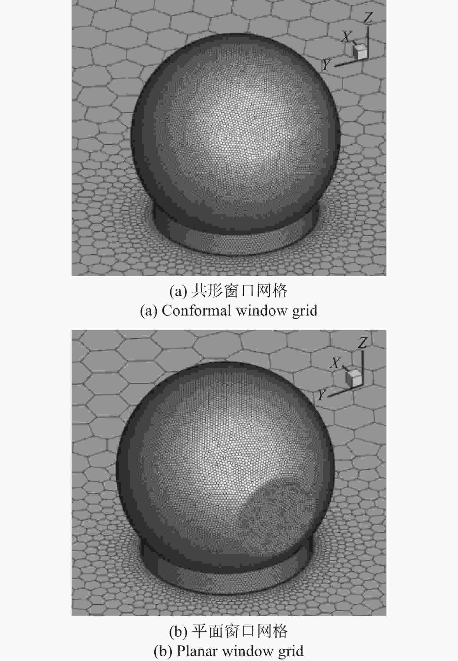
图 5 网格划分示意图
Figure 5. Schematic diagram of mesh division
-
气动光学效应主要有稳态与非稳态两类,在飞行速度较低时,带有整流罩的窗口的气动光学效应通常以稳态像差为主,占比达70%,并且稳态像差会弱化气动光学效应的非稳态特性[15]。由于非稳态气动光学效应十分复杂,难以进行光学补偿,并且占比不高,在很多情况下作为系统误差不予考虑。因此文中主要针对稳态气动光学效应进行分析。
目前,气动光学计算主要采用两种主流方法,即大涡模拟法(LES)和Reynolds平均法(RANS)。LES在提高计算精度方面取得了显著进展,但对于网格数量和计算机性能的要求较高。相比之下,RANS通过求解时均控制方程来模拟流场,具有模型建立简单、使用方便的优势,特别是在工程领域,RANS在保证一定准确性的情况下具有更高的计算效率。文中选择了RANS中的$ {k}-{\varepsilon } $两方程模型。该模型在满足雷诺应力的约束条件下,能够与真实湍流现象保持一致,能够更精确地模拟平面和原形射流的扩散速度,使计算结果更贴近真实情况。
-
当湍流介质密度发生变化时,湍流介质的折射率也会随之发生变化,通过GladStone-Dale关系式可知,折射率和空气中的密度直接相关,其表达式如下[16−17]:
$$ n(r) - 1 = {K_{GD}}\rho (r) $$ (1) 式中:$r = xi + yj + zk$,表示光线流场中的位置;$n(r)$和$\rho (r)$分别为该位置处的折射率和密度;${K_{GD}}$为与传播光线波长有关的G-D常数。${K_{GD}}$可以表示为:
$$ {K_{_{GD}}}(\lambda ) = 2.23 \times {10^{ - 4}}\left(1 + \frac{{7.52 \times {{10}^{ - 3}}}}{{{\lambda ^2}}}\right) $$ (2) 式中:$ \mathrm{\lambda } $为工作波长,单位为μm;${K_{GD}}$的单位为m3/kg。通过上式的计算,可以完成由气动流场的密度场分布到折射率场分布的转换过程。在几何光学中,光线沿路径对折射率的积分定义为光程(OPL),其表达式如下:
$$ OPL(x',y') =\displaystyle\int \nolimits_0^L n(x',y',z'){\mathrm{d}}z' $$ (3) 式中:$(x',y')$为光学窗口平面中的光学坐标;$z'$的发射方向。而光线在不均匀流场中的传播导致了各条光线光程的不同,被定义为光程差(OPD),其表达式如下:
$$ OPD(x',y') = OPL(x',y') - < OPL(x',y') > $$ (4) 式中:$ < OPL(x',y') > $表示平均光程差。根据波动方程的射线近似,可以得到光线在不均匀介质中的传播规律如下:
$$ \frac{{\text{d}}}{{{\text{d}}s}}\left[ {n(r)\frac{{{\text{d}}r}}{{{\text{d}}s}}} \right] = \nabla n(r) $$ (5) 式中:$ s $为光线传播路径上的弧长;$ r $为光线矢径;$ n $为折射率;$ \nabla n $为折射率梯度。公式(5)为典型的二阶常微分方程,文中使用四阶龙格—库塔法进行求解。
-
理想光束经过湍流大气后,远场光波波面相位将发生畸变。光波的波面相位畸变与光程差有关,用波长$ \mathrm{\lambda } $作参考量,光波的相位畸变为[9]:
$$ \Delta \phi =2\pi \frac{OPD(x{'},y{'},z{'})}{\lambda } $$ (6) 式中:$ \Delta \phi $为波面上的相位分布,即畸变之后的相位差。流场引起的光波相位畸变会严重影响光波的复振幅分布,设定光线的光波复振幅为$ E $,则远场的光波复振幅分布为:
$$ E(x{'},y{'},{z{'}}_{{\rm{far}}})=E(x{'},y{'},{z}_{0}{'}){\mathrm{exp}}[-i\Delta \phi ] $$ (7) 式中:$ E(x{'},y{'},{z}_{0}{'}) $为光瞳平面上的复振幅分布;$E(x{'},y{'},{z{'}}_{{\rm{far}}})$为远场平面的光波复振幅分布。根据波动光学可得,在远场平面的光强分布为:
$$ I(x{'},y{'},{z{'}}_{{\rm{far}}})={\left|E(x{'},y{'},{z{'}}_{{\rm{far}}})\right|}^{2} $$ (8) -
影响气动光学效应的因素有很多,文中重点分析两种光学窗口在不同转角、俯仰、飞行工况下的气动光学效应。图6(a)展示了光线追迹网格示意图,网格域尺寸为0.85R×0.85R×6R。光线追迹网格的解析依赖于对流场解析结果,需对流场解析结果进行空间插值。图6(b)为光线的传输过程,光从转塔内部发射,经过近场气动光学影响区域,得到波前畸变分布。
图 6 光线追踪示意图
Figure 6. Schematic diagram of ray tracing
图7为流场中的光线追迹示意云图,其中红色矩形框为光线追迹区域,圆形彩色为该工况下的波面畸变云图。图(a)、(b)展示了两种窗口在巡航高度和巡航速度下,方位转角为0°时的光线追迹示意图;图(c)和(d)展示了在90°方位转角时,两种窗口在不同俯仰情况下的光线追迹示意图;图(e)和(f)展示了在180°方位转角时,飞机在不同飞行工况下的光线追迹示意图。光线追迹的起始位置设置在光学窗口的圆心位置。整流罩内网格使用当地的折射率插值,而整流罩外的网格使用自由来流的折射率插值。光波波长选取$ \lambda $=0.632 μm,Gladstone-Dale系数为$ {K}_{GD}= 2.271\; 87\times{10}^{4}({{\mathrm{m}}}^{3}\cdot {{\mathrm{kg}}}^{-1}) $。飞机巡航速度为0.25 Ma,巡航高度为3.5 km。
图 7 光线追迹示意云图
Figure 7. Ray tracing schematic cloud map
-
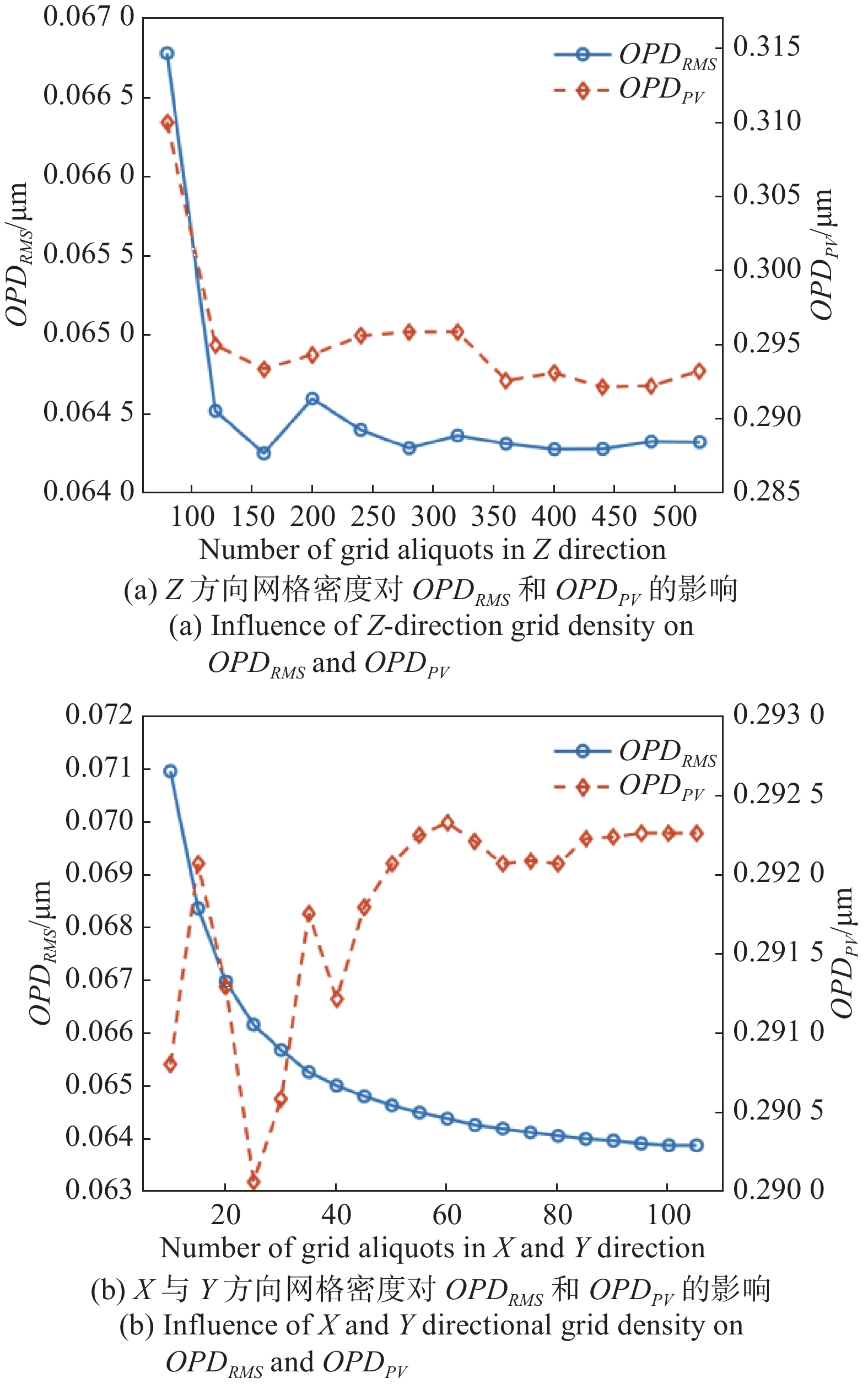
在壁面附近流场密度变化剧烈的情况下,合理的网格密度与积分距离十分重要,既要考虑分析结果的准确性,还要兼顾计算分析速度。图8为网格数量对${OPD}_{{{RMS}}}$和${OPD}_{{{PV}}}$影响的仿真分析结果图。其中横坐标为Z方向网格数量,左侧纵坐标表示$ {OPD}_{RMS} $值,右侧表示$ {OPD}_{PV} $值。由图8(a)可得,在Z方向网格数量较少时,$ {OPD}_{RMS} $和$ {OPD}_{PV} $存在震荡,随着网格密度的增加,震荡逐渐减小,均呈收敛趋势。图8(b)为X和Y方向的网格密度对$ {OPD}_{RMS} $和$ {OPD}_{PV} $的影响,随着网格密度增加,$ {OPD}_{RMS} $呈降低、收敛趋势;在网格密度较低时,$ {OPD}_{PV} $值波动较大,且曲线趋势与$ {OPD}_{RMS} $有较大的差异,随着网格数量的增加,其值变大并逐渐趋于收敛状态,产生波动的原因是网格密度不够造成采样样本点不足,从而导致$OPD(x',y')$计算值存在偏差,$ {OPD}_{PV} $对其畸变较为敏感。可见X和Y方向的网格分割数量对光线追迹结果的影响较大,在选择光学网格数量时要避开震荡剧烈区域。优化后网格等分数为100×100×480,单个网格尺寸为0.002 m×0.002 m×0.001625 m。

图 8 光学网格密度对${OPD}_{RMS}$和$ {OPD}_{PV} $的影响
Figure 8. Influence of optical grid density on ${OPD}_{RMS}$ and $ {OPD}_{PV} $
-
图9为在巡航速度、巡航高度下的两种窗口在不同转角时,${OPD}_{RMS}$随着光线追迹距离的变化趋势。由图可得,无论是共形窗口还是平面窗口,在积分长度大于6R后${OPD}_{RMS}$都趋于定值;平面窗口相对于共形窗口,${OPD}_{RMS}$随积分长度变化收敛更快。

图 9 两种窗口在不同方位角下光线追迹距离对${OPD}_{RMS}$的影响
Figure 9. Influence of ray tracing distance on ${OPD}_{RMS}$ for two windows at different AZ angles
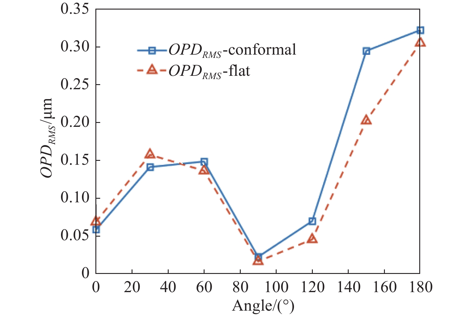
图10为两种窗口在光线追迹距离为6R时不同方位角下的$ {OPD}_{RMS} $对比图。由图可知,两种窗口在不同转角下的$ {OPD}_{RMS} $变化趋势基本相同;在0°~45°区间,$ {OPD}_{RMS} $随着转角增大而增加;在45°~90°区间,$ {OPD}_{RMS} $随转角增大而减低;在90°~180°区间,$ {OPD}_{RMS} $随转角增大而增大;在转角90°附近时,$ {OPD}_{RMS} $最小,在转角为180°时附近,$ {OPD}_{RMS} $最大。转角小于60°时,共型窗口的$ {OPD}_{RMS} $略小于共形窗口,超过60°之后,共形窗口的$ {OPD}_{RMS} $大于平面窗口,整体上共形窗口引起的$ {OPD}_{RMS} $略大于平面窗口引起的$ {OPD}_{RMS} $。
图 10 两种窗口在光线追迹距离为6R时不同方位角下的${OPD}_{RMS}$对比
Figure 10. ${OPD}_{RMS}$ comparison of two windows at different AZ angles for ray tracing distance of 6R
-
图11为巡航速度、巡航高度下,两种窗口在不同俯仰角时$ {OPD}_{RMS} $随着方位角变化曲线。由图(a)可以看出,改变俯仰角对共形窗口在不同方位角下$ {OPD}_{RMS} $影响较小,特别是在30°~120°几乎不受俯仰角的改变而影响,当方位转角大于150°时,俯仰角引起的$ {OPD}_{RMS} $差值开始增大;由图10(b)可得,当俯仰角度发生改变时,平面窗口引起的$ {OPD}_{RMS} $变化趋势与共形窗口基本相同,但变化值更明显。整体来看,两种窗口在方位转角小于150°时,俯仰角度对$ {OPD}_{RMS} $影响不大,在转角大于150°时$ {OPD}_{RMS} $急剧上升。这是因为光经过了整流罩后部的分离区,分离区使得流场变化更加复杂,同时计算域的下表面产生的附着流也会对$ {OPD}_{RMS} $产生较大的影响,当俯仰角度逐渐增大,附着流对$ {OPD}_{RMS} $的影响越来越小。

图 11 两种窗口在不同俯仰角下的${OPD}_{RMS}$对比
Figure 11. ${OPD}_{RMS}$ comparison of two windows at different EL angles
-
飞行高度和飞行速度也是影响窗口气动光学效应的重要因素。高度与速度的改变,对光学窗口附近流场的最大和最小值会产生变化,但其流场结构是相似的[18],如图6(e)、(f)所示,因此只针对$ {OPD}_{RMS} $最大处(方位180°)进行分析。分别设飞行高度值为1~7 km,飞行速度为0.1~0.35 Ma,得到$ {OPD}_{RMS} $变化曲线如图12所示。由图12(a)可以看出,在速度一定时,$ {OPD}_{RMS} $随着高度的增加呈线性减小,其中平面窗口相对于共形窗口具有更小的$ {OPD}_{RMS} $;由图12(b)可得,在高度一定时,$ {OPD}_{RMS} $随着速度的增加而呈指数型增加,平面窗口由速度引起的$ {OPD}_{RMS} $增加值相对于共形窗口更小。综合来看,增加飞行高度与减小飞行速度可以减弱气动光学效应,同时平面窗口相对于共形窗口引起的$ {OPD}_{RMS} $值变化更小。
图 12 两种窗口在不同飞行高度、速度下${OPD}_{RMS}$变化
Figure 12. ${OPD}_{RMS}$ variation of two windows at different flight altitudes and speeds
-
为了深入了解光学系统在实际工作条件下的表现,直观观察波面畸变对光学系统的影响,对上述计算的波面畸变进行了远场衍射分析。远场衍射分析不仅关注光束的传播行为,还涉及到光束如何与远处的目标相互作用,通过详细研究远场光斑的特性,能够更好地理解系统在远距离目标上的性能。
图13为两种光学窗口在不同工况下,光线在距离10 km的远场衍射下的光强分布云图。图(a)和(b)为原始光强分布与远场未畸变的理论光强分布,其中归一化后的远场未畸变的理论峰值光强为0.7784。图(c)~(j)为在巡航速度和巡航高度下的不同方位和俯仰角下的光斑变化情况。图(k)和(l)为飞行高度和速度变化后,方位角为180°时的光斑变化。由此可以看出,在不同工况下,远场畸变后的光斑均发生了不同程度的偏移和弥散。

图 13 远场衍射光强分布云图
Figure 13. Far-field diffraction intensity distribution map
图14为不同方位角下两种光学窗口的远场光斑光强变化与位置偏移量的变化曲线。光强差值定义为畸变后的云图峰值光强与远场理想未畸变光强之差,而偏移量则是峰值光强中心点与理想未畸变光强中心点之间的位置偏差。由图可得,在方位转角小于120°时,气动光学效应对远场衍射的光斑影响较小。然而,当方位角超过120°时,共形窗口的光强峰值迅速下降,而平面窗口的光强峰值有所增强,甚至超过了未畸变波面远场衍射的光强。根据惠更斯原理,波面畸变可能导致子波向一侧偏折和聚集,从而使光强峰值增加和位置发生偏移。当转角超过150°时,两种窗口的光斑偏移量均急剧上升,特别是平面窗口在方位转角达到180°时发生了严重的光斑位置偏移。总体而言,远场光斑发生偏移和弥散的程度与窗口附近的波面畸变成正相关,不同转角下光强变化与偏移量随方位角的变化趋势与图10相似。随着方位角的增加,光强与偏移量的变化更为剧烈,尤其是对于平面窗口,在方位角大于150°后,其波面畸变相较于共形窗口更为严重。
图 14 光强差值与偏移量随方位角变化曲线
Figure 14. Curves of intensity difference and offset with AZ angle variation
图15为方位转角在180°时,两种光学窗口在不同飞行高度和速度下的光强与偏移量变化曲线。图(a)为飞行速度为0.25 Ma时,两种窗口在不同飞行高度下的光强和偏移量变化规律图,可以看出,随着高度的增加,两种窗口的峰值光强均呈线性增加,而偏移量几乎保持不变。在7 km高度时与两种窗口引起的偏移量基本相同。这表明随着高度的增加,窗口形状对气动光学效应的影响逐渐减小。图(b)为飞行高度为3.5 km时,两种窗口在不同飞行速度下光强与偏移量变化规律图,可以看出,两种窗口的峰值光强随飞行速度的增加均呈线性减少,且平面窗口的峰值光强随高度的增加衰减更为严重,当改变飞行速度时,窗口形状对光斑偏移量的影响较小,相较于高度,速度对气动光学效应的影响更为显著。同时,在图10中方位角为180°时,平面窗口RMS值虽小于共形窗口,但在远场衍射时光斑的弥散程度强于共形窗口。

图 15 光强差值与偏移量随飞行高度与速度变化曲线
Figure 15. Curves of intensity difference and offset variation with flight altitude and speed
结合图13~15可知,近场气动光学效应对远场衍射光斑有较大的影响,增加了${OPD}_{RMS}$,造成远场光斑发生较大的偏移和弥散,例如在飞行高度为3.5 km、飞行速度为0.25 Ma时,光强衰弱60%,已经超出了激光通信通常设计的通信光束能量与散角大小,因此既要考虑光强变化,需要优化设计参数或增加额外的光束角度微调整机构。
-
针对机载激光通信中气动光学效应对光束传输的影响问题。通过稳态分析对比了共形窗口和平面窗口在不同方位角、俯仰角、飞行高度和飞行速度条件下气动光学效应对光束能量分布和位置偏移的影响。通过详细的仿真分析,得出以下结论:
1) 方位角小于90°时,两种窗口的光学传输性能相差不大,当方位角超过90°时,共形窗口的RMS值始终高于平面窗口。然而,经过波面畸变远场衍射后,共形窗口的光斑畸变明显小于平面窗口,尤其方位角达为180°时,平面窗口的远场光斑出现了明显的峰值光强减弱与光斑弥散。当改变俯仰角时,共形窗口相较于平面窗口表现出良好的稳定性。
2) 改变飞行高度与飞行速度对远场衍射光斑的峰值光强产生较大的影响,但对光斑的偏移量影响较小。增加飞行高度会弱化窗口形状对气动光学效应的影响,而增加飞行速度又会使两种窗口出现明显的差距,飞行速度相较飞行高度对气动光学效应影响更强。
由气动光学效应引起的波面畸变十分复杂,仅依靠波像差RMS值不能完全定义其对光学系统的影响,如方位180°时平面窗口RMS值虽小于共形窗口,但在远场衍射时光斑的弥散程度强于共形窗口。总体而言共形窗口在俯仰、高度和速度变化中的流场更加稳定,呈现更为一致的变化趋势,且在远场衍射中表现更好。而平面窗口在方位转角变化大与低速的飞行工况下,平面窗口的RMS值低于共形窗口。因此,在光学系统设计时,需综合考虑气动光学效应引起的光强变化和位置偏移,选择适用于具体工况的光学窗口形状。
Analysis of aerodynamic optical effects in airborne laser communication optical windows
-
摘要: 机载激光通信中通信光束散角小、系统跟踪精度高,光学窗口的气动光学效应会引起远场光斑形状和位置发生变化,降低通信性能。为此,通过Fluent对共形和平面两种光学窗口整流罩在不同飞行高度、速度、方位角下的外流场进行稳态仿真分析,利用相位屏分析远场自由衍射光斑变化。结果表明,共形窗口在俯仰、高度和速度变化中的流场更加稳定,呈现更为一致的变化趋势,且在远场衍射中表现更好。平面窗口在方位转角变化大与低速的飞行工况下,RMS值低于共形窗口。远场光斑发生偏移和弥散的程度与波面畸变成正相关,但在波面畸变较大的情况下,RMS值不能完全定义其对光学系统的影响。同时,当俯仰角靠近机体表面、降低飞行高度、增加飞行速度均会增强波面畸变。Abstract:
Objective Wireless laser communication technology has advantages such as high communication speed, good security, and portability, making it widely applicable in both military and civilian communication fields. Aircraft, as one of the crucial platforms for wireless laser communication research, can effectively enhance the reliability and applicability of laser communication, playing a significant role in the future integrated aerospace network. However, the practical application of airborne laser communication faces various challenges. Apart from common atmospheric laser communication issues like atmospheric absorption, scattering, platform vibrations, and cloud cover, aerodynamic optical effects pose a significant constraint on the application of airborne laser communication. Methods This paper addresses the issue of selecting the shape of the optical window for the airborne laser communication optical terminal. It designs streamlined fairings with conformal and planar optical window shapes (Fig.3). Fluent is used to simulate and analyze the flow field around the fairings under different flight altitudes, speeds, and azimuth angles. The refractive index distribution at the front end of the optical window is obtained based on the density and refractive index relationship (Fig.7). Then, using the ray tracing method, the wavefront distortion of the two windows under different conditions is obtained (Fig.6), verifying the independence of the optical grid and tracing length in ray tracing (Fig.8-9). Finally, the far-field free diffraction spot changes are analyzed using phase screen analysis (Fig.13). Results and Discussions The results show that, at different azimuth angles, RMS increases first and then decreases, reaching a minimum at 90°, and rapidly increasing after exceeding 90°, reaching the maximum at 180° (Fig.10). Overall, the RMS caused by the spherical window is slightly larger than that caused by the planar window. When changing the pitch angle, the spherical window exhibits good flow field consistency, while the planar window has some influence on the flow field near the window (Fig.11). Flight altitude and speed are also crucial factors affecting window aerodynamic optical effects. Increasing flight altitude and decreasing flight speed can weaken aerodynamic optical effects, and the RMS change caused by the planar window is smaller than that caused by the conformal window (Fig.12). To gain a deeper understanding of the performance of the optical system under actual working conditions and observe the impact of wavefront distortion on the optical system, we conducted far-field diffraction analysis of the calculated wavefront distortion. With increasing azimuth angle, the changes in intensity and offset become more drastic, resembling the trend of RMS changes. However, for the planar window, after azimuth angle exceeds 150°, its wavefront distortion becomes more severe compared to the conformal window (Fig.14). Increasing flight altitude can weaken the window's impact on aerodynamic optics, and increasing flight speed results in noticeable differences between the two, with speed having a more significant impact on aerodynamic optical effects than altitude (Fig.15). Conclusions When the azimuth angle is less than 90°, there is little difference in the optical transmission performance between the two window shapes. However, beyond 90°, the RMS value of the conformal window consistently exceeds that of the planar window. Nevertheless, after wavefront aberration and far-field diffraction, the distortion of the spot from the conformal window is noticeably smaller than that from the planar window, especially at azimuth angles of 180°, where the planar window's far-field spot shows significant peak intensity reduction and spreading. Changes in pitch angle demonstrate better stability for the conformal window compared to the planar window. Variations in flight altitude and speed significantly affect the peak intensity of the far-field diffraction spot, while having a smaller impact on the spot's displacement. Increasing flight altitude weakens the influence of the window shape on aerodynamic optical effects, while increasing flight speed exacerbates the differences between the two window shapes, with flight speed having a stronger impact on aerodynamic optical effects compared to flight altitude. The wavefront aberrations caused by aerodynamic optical effects are highly complex, and relying solely on wavefront aberration RMS values cannot fully define their impact on the optical system. For instance, although the RMS value of the planar window is smaller than that of the conformal window at azimuth 180°, the spreading degree of the spot during far-field diffraction is stronger than that of the conformal window. Overall, the conformal window exhibits more stable flow fields during variations in pitch, altitude, and speed, showing a more consistent trend and performing better in far-field diffraction. Conversely, the planar window's RMS value is lower than that of the conformal window under conditions of large azimuth angles and low-speed flight. -
Key words:
- airborne laser communication /
- aero-optics /
- far-field diffraction /
- optical window
-
图 1 机载激光通信光端机整体结构
Figure 1. Overall structure of airborne laser communication optical terminal
图 2 机载激光通信光端机光路示意图
Figure 2. Schematic diagram of the optical path in the airborne laser communication optical terminal
图 3 光学窗口几何模型示意图及视角定义
Figure 3. Geometric model schematic of the optical window and definition of viewing angles
图 8 光学网格密度对${OPD}_{RMS}$和$ {OPD}_{PV} $的影响
Figure 8. Influence of optical grid density on ${OPD}_{RMS}$ and $ {OPD}_{PV} $
图 9 两种窗口在不同方位角下光线追迹距离对${OPD}_{RMS}$的影响
Figure 9. Influence of ray tracing distance on ${OPD}_{RMS}$ for two windows at different AZ angles
图 10 两种窗口在光线追迹距离为6R时不同方位角下的${OPD}_{RMS}$对比
Figure 10. ${OPD}_{RMS}$ comparison of two windows at different AZ angles for ray tracing distance of 6R
图 11 两种窗口在不同俯仰角下的${OPD}_{RMS}$对比
Figure 11. ${OPD}_{RMS}$ comparison of two windows at different EL angles
图 12 两种窗口在不同飞行高度、速度下${OPD}_{RMS}$变化
Figure 12. ${OPD}_{RMS}$ variation of two windows at different flight altitudes and speeds
图 14 光强差值与偏移量随方位角变化曲线
Figure 14. Curves of intensity difference and offset with AZ angle variation
-
[1] Jiang Huilin, Fu Qiang, Zhao Yiwu, et al. Development status and trend of space information network and laser communication [J]. Journal of the Internet of Things, 2019, 3(2): 1-8. (in Chinese) [2] Xing Zhan, Chen Xiaoyi, Peng Zhiyong, et al. Research progress and thinking of infrared aero-optical effect (Invited) [J]. Infrared and Laser Engineering, 2022, 51(4): 20220228. (in Chinese) [3] Sun Xiwang, Liu Wei. Research progress of aero-optical effect [J]. Advances in Mechanics, 2020, 50(0): 249-309. (in Chinese) [4] Weber D C, Trolinger J D, Rose W C. Computer simulation of aero-optic phenomena based on empirical data [J]. Optical Diagnostics for Fluids, Solids, and Combustion, 2001, 4448: 187-196. doi: 10.1117/12.449376 [5] Duffin D A, Jumper E J. Feedforward adaptive-optic correction of aero-optical aberrations caused by a two-dimensional heated jet [J]. AIAA Journal, 2011, 49(6): 1283-1291. doi: 10.2514/1.J050904 [6] Porter C, Gordeyev S, Zenk M, et al. Flight measurements of aero-optical distortions from a flat-windowed turret on the airborne aero-optics laboratory (AAOL)[C]//42nd AIAA Plasmadynamics and Lasers Conference in Conjunction with the 18th International Conference on MHD Energy Conversion (ICMHD), 2011: 3280. [7] White M, Visbal M. Computational investigation of wall cooling and suction on the aberrating structures in a transonic boundary layer[C]//51st AIAA Aerospace Sciences Meeting Including the New Horizons Forum and Aerospace Exposition, 2013: 720. [8] Yin Xingliang. Principles of Aero-optics[M]. Beijing: China Astronautic Publishing House, 2003. (in Chinese) [9] Li Guichun. Aerodynamic Optics [M]. Beijing: National Defense Industry Press, 2003. (in Chinese) [10] Meng Lixin, Zhao Dingxuan, Zhang Lizhong, et al. Boundary layer effect and compensation in airborne laser communication [J]. Optics and Precision Engineering, 2014, 22(12): 3231-3238. (in Chinese) doi: 10.3788/OPE.20142212.3231 [11] Ding Haolin, Yi Shihe, Fu Jia, et al. Experimental investigation of aero-optical effect due to supersonic turbulent boundary layer [J]. Infrared and Laser Engineering, 2016, 45(10): 192-198. (in Chinese) [12] Zhao Xinhai, Yi Shihe, Ding Haolin, et al. Experiment on optical path difference of supersonic semi-free jet [J]. Acta Optica Sinica, 2020, 40(7): 0701001. (in Chinese) [13] Tan Xiaotong, Xu Heyong, Tian Renzhi. Numerical simulation of aero-optical effect of flow around typical optical windows [J]. Acta Aerodynamica Sinica, 2023, 41(6): 71-80. (in Chinese) [14] Dong Hang, Xu Ming. Space-time characteristics of the aero-optical effect around turrets [J]. Acta Optica Sinica, 2018, 38(10): 1001002. (in Chinese) [15] Chen Yong, Xie Weiming, Lu Daju, et al. Study on unsteady aero-optical effect of turret wake [J]. Acta Optica Sinica, 2020, 40(16): 1601001. (in Chinese) [16] Zhang Qingpeng. Study on suppression method of aero-optical effect of beamexpanding system[D]. Chengdu: The Institute of Optics and Electronics, the Chinese Academy of Sciences, 2020. (in Chinese) [17] Thuerey N, Weißenow K, Prantl L, et al. Deep learning methods for Reynolds-averaged Navier–Stokes simulations of airfoil flows [J]. AIAA Journal, 2020, 58(1): 25-36. doi: 10.2514/1.J058291 [18] Xu Liang, Wang Luyang, Wan Ziming, et al. Influence of different altitudes on deviation of aero-opticsimaging of 0°-15° angle of attack [J]. Infrared and Laser Engineering, 2023, 52(5): 20230411. (in Chinese) -

 点击查看大图

计量
- 文章访问数: 45
- HTML全文浏览量: 4
- PDF下载量: 9
- 被引次数: 0

