


-
脉冲式激光测距机具有体积小、测距速度快、测距精度高、低消耗性等优点,可以快速准确测量系统与目标之间的间隔,精确获取敌我距离信息,从而更好的发挥武器性能,是多种战场上使用的目标瞄准技术的基础,被广泛应用于大量的军事装备[1−5]。因此对敌方激光测距机实施干扰,使其不能获取正确的目标距离信息具有重要的意义。
对激光测距机的干扰可分为欺骗干扰和致盲干扰两种:欺骗干扰可以利用高重频激光干扰设备发射大量随机激光脉冲,使激光测距机的回波信号淹没在众多干扰激光脉冲之中,以致测距机无法提取真正的测距回波,从而输出虚假的距离值;致盲干扰是利用高功率激光对测距机接收窗口进行照射,使光电探测器等敏感部件性能下降或失效,从而导致测距机无法测得有效距离或被毁伤[6−13]。
在敌我双方距离较远时,实现致盲干扰对激光器的性能及配套跟瞄设备的精度要求均较高,导致了成本和实现难度的增加。所以在干扰激光测距机时,使用更多的是高重频激光干扰技术[14−17]。当前对于该项技术的研究多为理论分析,极少有试验验证。文中通过多次外场试验,分别探究了在固定距离下,高重频激光的功率和重复频率对脉冲式激光测距机干扰效能的影响,及不同重复频率的激光在不同距离下的有效干扰率。对试验数据进行分析,获得了不同干扰条件下测距机测得的距离值分布规律,对实际工程应用具有一定的参考价值。
当前在军事中大量应用的是波长为1064 nm的Nd:YAG激光测距机,这也是此次研究选取的对抗目标。对于其他波长的激光测距机,高重频激光干扰的原理与文中一致,但需选用相同波长激光干扰机进行干扰。
-
脉冲式激光测距机测距原理如图1所示:测距机中脉冲激光器产生的固定重复频率激光被分为两束,一束进入激光取样器件作为计时起始信号(见图1红色箭头);另一束经过大气传输后到达目标并经过目标的反射进入接收光学系统,被光电探测器转换为电信号,电信号经过放大器和滤波器后在阈值比较器中与测距机设定的阈值进行比较,通过阈值比较器的成为回波信号,该信号即为计数器的计时停止信号(见图1蓝色箭头)。通过测量参考信号和回波信号间的时间差计算出目标与测距机之间的距离[18−20]。计算公式如下:

图 1 脉冲式激光测距机测距原理框图
Figure 1. Principle block diagram of pulsed laser rangefinder
$$ L = \frac{{c\Delta t}}{{2n}} $$ (1) 式中:L为测距机与目标间的距离;c为光速($3 \times {10^8}$ m/s);$\Delta t$为激光脉冲往返传输时间;n为大气折射率,取近似值n=1。
-
如图2所示,在激光测距机测距时,高重频激光干扰设备向测距机发射干扰激光脉冲,干扰脉冲信号超前于测距回波信号进入测距机接收系统,使得距离计数器提前停止计数,从而输出虚假的距离值[16]。
图 2 高重频激光对测距机干扰原理图
Figure 2. Jamming principle diagram of high-repetition rate laser to rangefinder
为使敌方测距机测距时总会收到干扰信号得出虚假测距结果,高重频激光的重复频率f应满足:
$$ f \geqslant \frac{c}{{2nL}} $$ (2) 则重频f所对应的最小干扰距离L0为:
$$ {L_0} = \frac{c}{{2nf}} $$ (3) 式中:f为干扰激光脉冲重复频率;L为干扰距离;c为光速($3 \times {10^8}$ m/s);n为大气折射率。由公式(3)可知,不同重复频率的干扰激光对应的最小干扰距离不同。
为使干扰激光脉冲到达测距机光学接收系统时的功率大于测距机的最小可探测功率,其输出功率需满足以下条件:
$$ {P_{\min }} \geqslant {P_r}\pi {L^2}{\theta ^2}{{\rm{e}}^{\alpha L}}/4{\eta _\tau }{\eta _r}A $$ (4) 式中:${P_r}$为测距机的最小可探测功率;$L$为干扰距离;$\theta $为干扰激光束散角;$\alpha $为大气衰减系数;$ {\eta _\tau } $为干扰机发射光学系统透射率;${\eta _\gamma }$为激光测距机接收光学系统透射率;$A$为测距机接收窗口面积。此时干扰激光的平均输出功率为:
$$ {P_v} = f{P_{\min }}\tau $$ (5) 式中:$ \tau $为干扰激光脉冲宽度;$f$为脉冲重复频率[17]。
-
试验装置主要由激光测距机、高重频激光干扰机、被保护目标组成,其布设图如图3所示。
图 3 试验装置布设图
Figure 3. Layout diagram of test equipment
在进行远距离干扰时,高重频激光干扰机布设在被保护目标附近,与被保护目标间距离可忽略,因此有L1=L2=L。试验场当日能见度约为V=15 km。干扰激光脉冲的波长为$\lambda $= 1 064 nm,束散角为$\theta $= 3.5 mrad,干扰机发射光学系统透射率为$ {\eta _\tau } $=0.7,试验所用脉冲测距机测距精度为5 m。主要参数如表1所示,其中f1为测距脉冲的重复频率。
表 1 激光测距机参数
Table 1. Parameters of laser rangefinder
Parameter Value Pr/W 4×10⁻⁸ ${\eta _\gamma }$ 0.7 A/mm Φ40 f1/Hz 5 -
为探究干扰激光功率对干扰效能的影响,当测距机布设于距干扰机L=15 km处时,将干扰激光的重复频率设为150 kHz,此时干扰激光脉冲宽度为$ \tau $= 200 ns。则可由公式(3)得出最小干扰距离为L0=1 km,公式(4)与(5)求得:Pmin=2.092 W、Pv=62.77 mW。试验中测量的输出功率是平均输出功率Pv。实际应用中,测距机的信息处理系统增益控制电路会根据回波功率来设置最小接收功率阈值,因此能进入接收系统并被处理的干扰激光脉冲峰值功率往往需大于理论计算值。
测距误差通常源于测距机内部与外界的随机干扰,其特征为:误差来源多却没有一个起决定性作用的因素。按照高斯误差理论,测距误差应服从正态分布[12]。试验中所用测距机的测距精度$\sigma $优于测量值的0.1%,根据测量误差理论,测距误差落在$ \pm 6\sigma $范围内的概率为99.99966%。因此在判定是否干扰成功时,可以$6\sigma $为界判定干扰效果,若实施干扰后,测距误差超出$6\sigma $,则判定干扰有效。在实际试验中,干扰效果是具有随机性的,因此需要重复试验统计有效干扰率P作为干扰效能的评价标准,即有效干扰率=有效干扰次数/总试验次数,P越大干扰效能越好。
在无干扰条件下使用测距机测量目标与测距机间的距离,重复100次,测距结果分布如图4所示,所获结果均在测距精度范围内,取占比最大且最接近平均数的15110 m为距离真值。
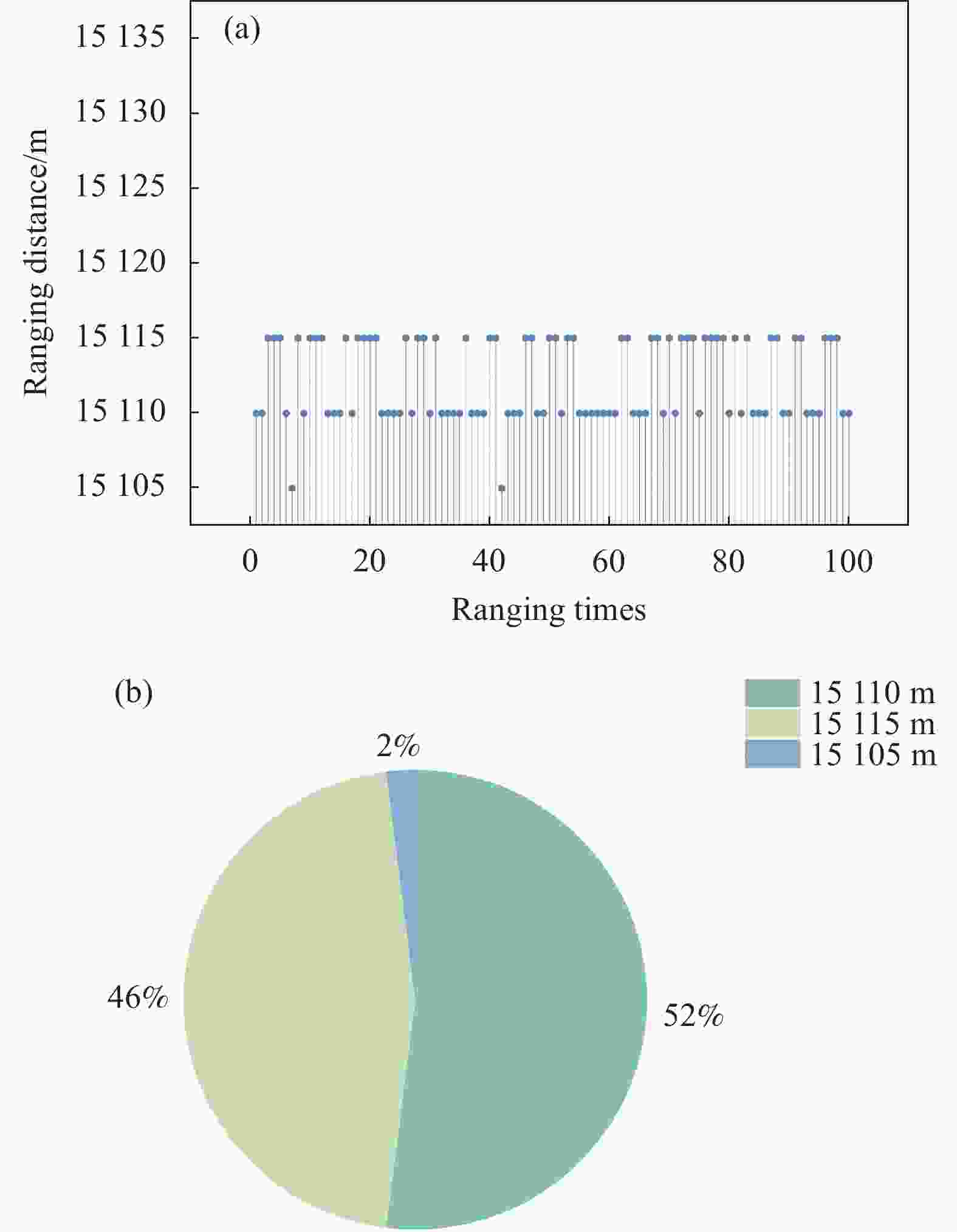
图 4 (a) 无干扰时测距结果散点图;(b) 无干扰时测距结果分布饼图
Figure 4. (a) Scatter plot of ranging result without jamming; (b) Ranging result distribution pie diagram without jamming
分别在泵浦电流I为10.5、11.0、11.5、12.0、12.5、13.0 A时,使用高重频激光干扰设备向测距机发射重频为150 kHz的干扰激光,每组试验测距100次。不同泵浦电流下的输出功率与有效干扰率如表2所示。
表 2 f=150 kHz不同泵浦电流下的输出功率及有效干扰率
Table 2. Output power and effective jamming rate under different pump at f=150 kHz
Pump currents/A Output power/W Effective interference rate 10.5 0.071 16% 11.0 0.092 45% 11.5 0.368 100% 12.0 0.828 100% 12.5 1.380 100% 13.0 1.748 100% 测距结果则如图5所示,在干扰激光功率不够时,高重频激光对测距机的干扰效果十分有限甚至不能起到干扰作用。且激光器输出脉冲的功率具有一定的波动,则获得尽可能高的有效干扰率,根据工程经验需使输出高重频激光的平均功率在理论计算最小值的3倍以上。
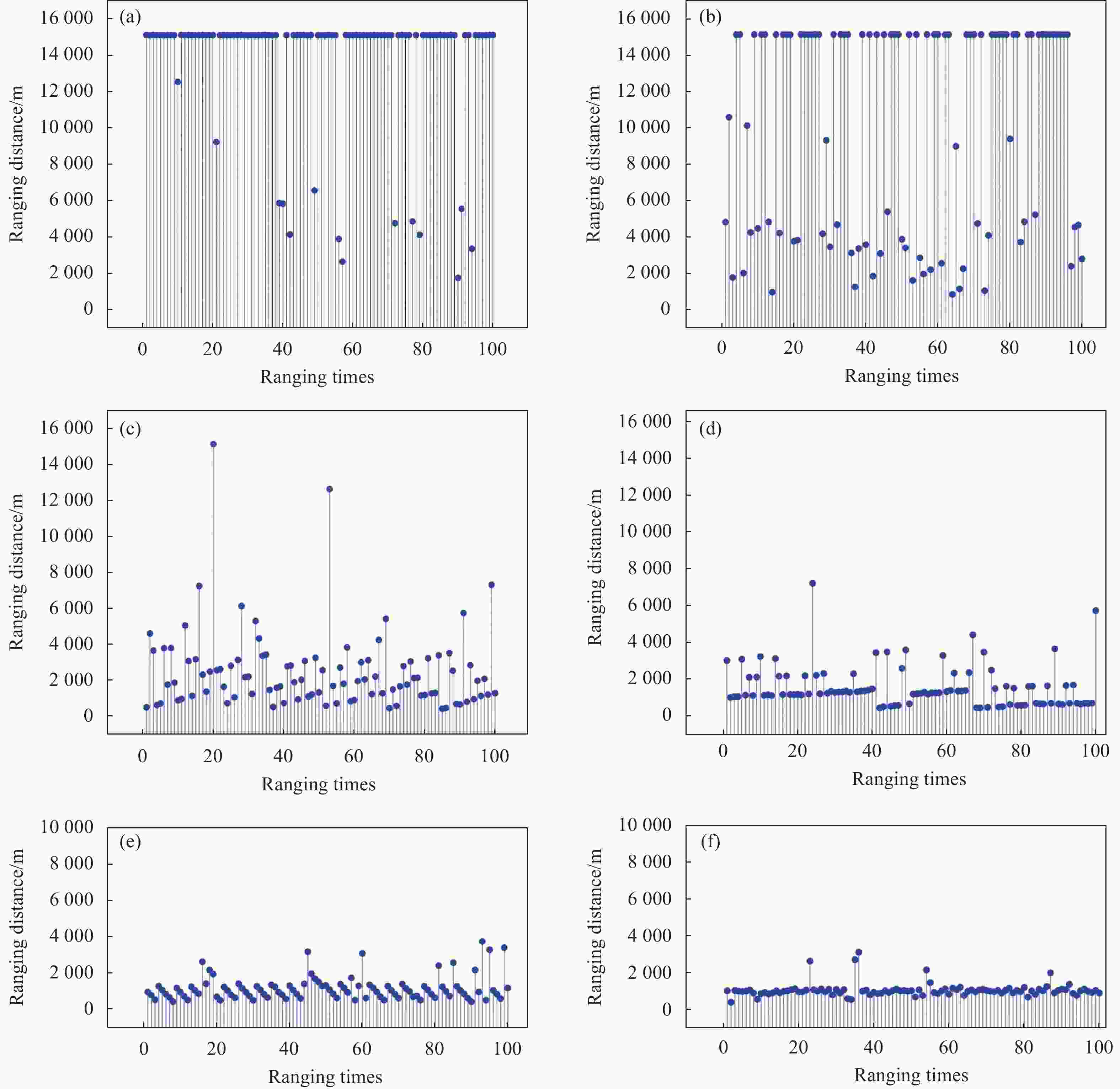
图 5 (a) 泵浦电流I=10.5 A,重复频率f=150 kHz测距结果散点图;(b) 泵浦电流I=11 A,重复频率f=150 kHz测距结果散点图;(c) 泵浦电流I=11.5 A,重复频率f=150 kHz测距结果散点图;(d) 泵浦电流I=12 A,重复频率f=150 kHz测距结果散点图;(e) 泵浦电流I=12.5 A,重复频率f=150 kHz测距结果散点图;(f) 泵浦电流I=13 A,重复频率f=150 kHz测距结果散点图
Figure 5. (a) Scatter plot of ranging result at pump power is 10.5 A When frequency is 150 kHz; (b) Scatter plot of ranging result at pump power is 11 A When frequency is 150 kHz; (c) Scatter plot of ranging result at pump power is 11.5 A When frequency is 150 kHz; (d) Scatter plot of ranging result at pump power is 12 A When frequency is 150 kHz; (e) Scatter plot of ranging result at pump power is 12.5 A When frequency is 150 kHz; (f) Scatter plot of ranging result at pump power is 13 A When frequency is 150 kHz
当干扰机泵浦电流I为11.5 A及以上时,有效干扰率均为100%,受干扰后测距结果的最小值均分布于测距机盲区周围,最大值随着功率的增加逐渐减小。
对这些结果进行分布拟合,拟合结果如图6所示,均近似呈正态分布,且随着输出功率增加,分布中心逐渐趋近于最小干扰距离1 km,方差也在逐渐减小至一个稳定的范围。说明在干扰成功时,若干扰激光的功率足够大,则所测得的虚假距离值会以干扰激光重频所对应的最小干扰距离为期望呈正态分布。由此可粗略估算出引入高重频激光干扰时,测距机测得的虚假距离值分布,对实际应用具有参考意义。

图 6 f=150 kHz测距结果分布拟合图
Figure 6. Fitting diagram of ranging result distribution at f=150 kHz
-
当干扰激光脉冲的重复频率为50 kHz时,脉冲宽度$ \tau $= 180 ns,最小干扰距离为L0=3 km,Pv= 18.83 mW。同理,重频为30 kHz时,脉冲宽度$ \tau $= 170 ns,最小干扰距离L0=5 km,Pv= 10.67 mW。
通过预试验发现,在泵浦电流为10.5 A时,无论干扰激光脉冲的重复频率为50 kHz还是30 kHz,有效干扰率均达到100%。因此,分别在泵浦电流为10.5、11.0、11.5、12.0 A时,使用高重频激光干扰设备向测距机发射重频为50 kHz的干扰激光,每组试验测距100次,测距结果如图7所示。将干扰激光的重复频率调整至30 kHz,其余条件不变,重复上述试验,测距结果如图8所示。在不同重复频率的干扰激光干扰下,测得距离的最小值仍分布于测距机盲区周围,不随频率的改变而变化;最大值随功率的增加逐渐减小,且在同一泵浦电流下,干扰激光的重复频率越低,测距机测距结果中的最大值越大。对测距结果进行分布拟合,拟合结果如图9所示。

图 7 (a) 泵浦电流I=10.5 A,重复频率f=50 kHz测距结果散点图;(b) 泵浦电流I=11 A,重复频率f=50 kHz测距结果散点图;(c) 泵浦电流I=11.5 A,重复频率f=50 kHz测距结果散点图;(d) 泵浦电流I=12 A,重复频率f=50 kHz测距结果散点图
Figure 7. (a) Scatter plot of ranging result at pump power is 10.5 A, when frequency is 50 kHz; (b) Scatter plot of ranging result at pump power is 11 A, when frequency is 50 kHz; (c) Scatter plot of ranging result at pump power is 11.5 A, when frequency is 50 kHz; (d) Scatter plot of ranging result at pump power is 12 A, when frequency is 50 kHz
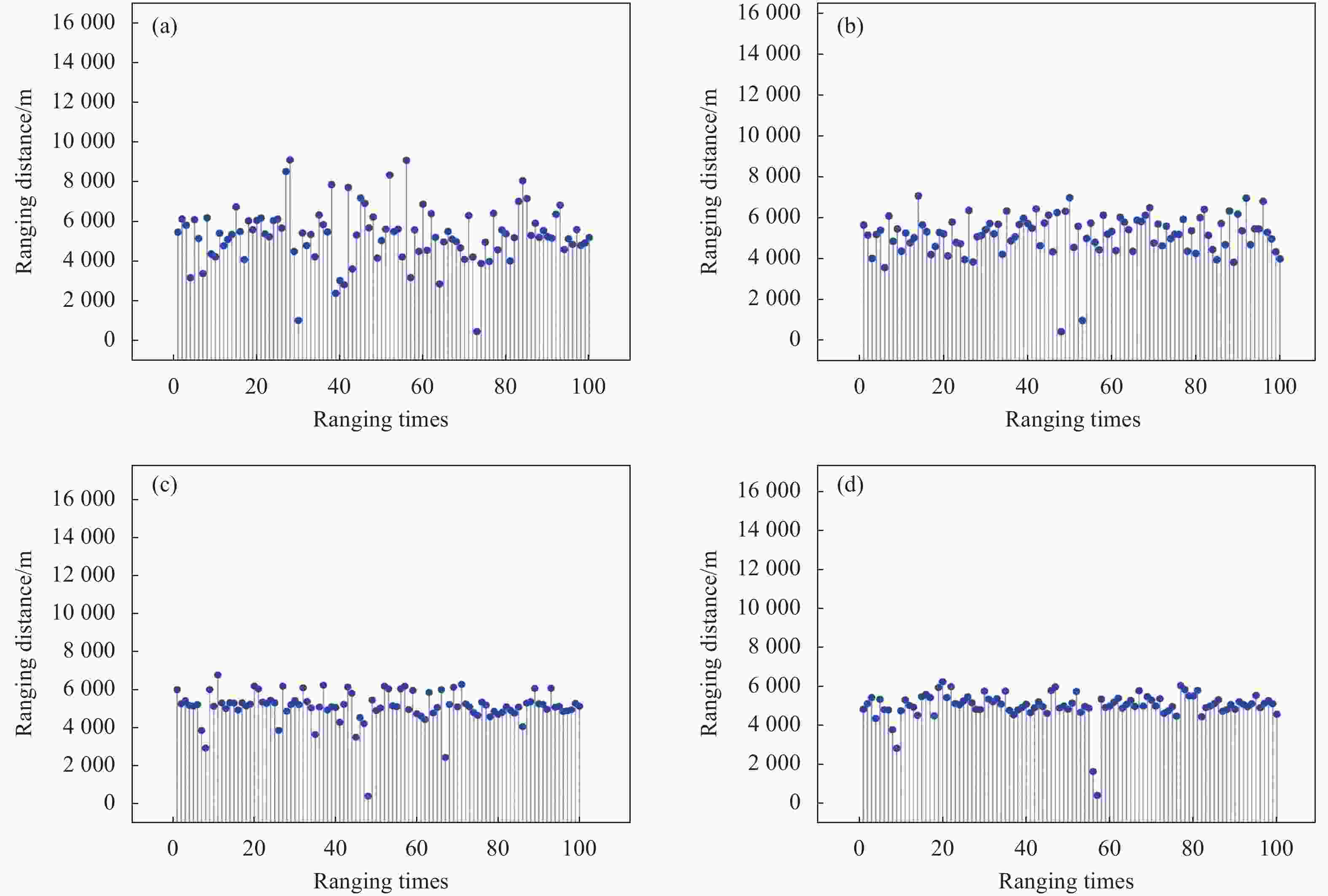
图 8 (a) 泵浦电流I=10.5 A,重复频率f=30 kHz测距结果散点图;(b) 泵浦电流I=11 A,重复频率f=30 kHz测距结果散点图;(c) 泵浦电流I=11.5 A,重复频率f=30 kHz测距结果散点图;(d) 泵浦电流I=12 A,重复频率f=30 kHz测距结果散点图
Figure 8. (a) Scatter plot of ranging result at pump power is 10.5 A, when frequency is 30 kHz; (b) Scatter plot of ranging result at pump power is 11 A, when frequency is 30 kHz; (c) Scatter plot of ranging result at pump power is 11.5 A, when frequency is 30 kHz; (d) Scatter plot of ranging result at pump power is 12 A, when frequency is 30 kHz
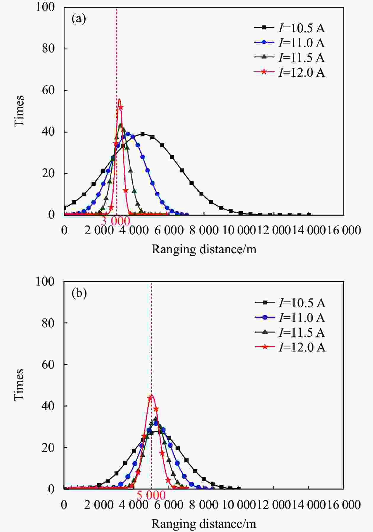
图 9 (a) f=50 kHz测距结果分布拟合图;(b) f=30 kHz测距结果分布拟合图
Figure 9. (a) Fitting diagram of ranging result distribution at f=50 kHz; (b) Fitting diagram of ranging result distribution at f=30 kHz
拟合结果均近似呈正态分布,且随着输出功率增加,正态分布的中心趋近于相应重频所对应的最小干扰距离,方差也逐渐减小至趋于稳定,与3.1小节结论相符。
在泵浦电流为12 A时,改变高重频激光的重复频率,探究不同干扰距离下的有效干扰率,试验结果如表3所示。由此可知,当实际干扰距离大于最小干扰距离时,有效干扰率为100%。当干扰激光的功率满足干扰需求时,干扰激光的重复频率越高,有效干扰距离范围越大,最小干扰距离越小;若实际干扰距离L小于最小干扰距离L0,干扰效能会降低。
表 3 不同重频的激光在不同距离下的有效干扰率
Table 3. Effective jamming rate of laser with different repetition rate at different distance
Distance/
kmf=30 kHz
effective jamming ratef=50 kHz
effective jamming ratef=150 kHz
effective jamming rate1 20% 33% 100% 3 60% 100% 100% 5 100% 100% 100% 7 100% 100% 100% 9 100% 100% 100% 当实际干扰距离小于最小干扰距离时,重频为f的干扰激光相邻两脉冲间的时间间隔为:
$$ {t_1} = \frac{1}{f} $$ (6) 光在实际干扰距离L内往返所需时间为:
$$ {t_2} = \frac{{2nL}}{c} $$ (7) 此时,有效干扰率为:
$$ P = \frac{{{t_2}}}{{{t_1}}} $$ (8) 因此,在实际应用中应尽可能增大干扰激光的重复频率以增大有效干扰率。
-
文中结合理论分析与外与场试验,将有效干扰率作为效能评估的标准,提出了一种判断高重频激光是否对脉冲式激光测距机进行了有效干扰的方法。并通过对试验数据的处理和分析,得到了不同距离下,高重频干扰激光的功率、重复频率对脉冲式激光测距机测距结果的影响规律:
1)干扰激光对应的最小干扰距离由其重复频率决定,当实际干扰距离大于最小干扰距离时,若其功率不足,则无干扰效果;
2)在干扰成功状态下继续增加干扰激光功率,测距机测得距离的最小值分布于测距机盲区附近,整体测距结果趋于正态分布,且功率越高,期望值越接近于干扰激光重频所对应的最小干扰距离;
3)当干扰激光的功率足够时,干扰激光重复频率越高,最小干扰距离越小,有效干扰范围越大。
文中工作为如何评价高重频激光对测距机的干扰是否成功提供了思路。且在试验中发现的规律对于实际工程具有一定的参考意义,成功快速干扰脉冲式测距机需要高重复频率的较强激光束,受干扰后的测距结果呈以最小干扰距离为中心的正态分布。笔者下一步工作的重点是更为深入的分析不同条件下测距机测得的虚假距离分布情况,寻找新的对抗思路,探究改变相关参数以控制敌方测距机输出结果的可行性。
Experimental study on the jamming of high-repetition rate laser to rangefinder
-
摘要: 高重频激光干扰是对脉冲式激光测距机的一种有效干扰手段,为探究高重频激光对测距机干扰效能的影响因素及规律,开展相关的理论分析与试验研究。试验研究了干扰激光的功率、重复频率及干扰距离对测距机干扰效能的影响。结果表明:存在一个与干扰激光频率相关的最小干扰距离,干扰激光的重复频率越高,最小干扰距离越小,有效干扰距离范围越大。当实际干扰距离大于最小干扰距离时,若干扰激光的功率不足,则无干扰效果;干扰成功后继续增大干扰激光功率,则被干扰后测距结果会趋于正态分布,且干扰激光功率越高,测距结果正态分布中心越趋近于最小干扰距离,但受干扰的测距结果最小值会始终分布于测距机盲区附近。Abstract:
Objective Because of the advantages of small size, fast measurement speed, low consumption and high ranging accuracy, pulsed laser rangefinder is widely used in a wide range of military equipment. Therefore, it is crucial to ensure that it is impossible to obtain the correct target distance information. Jamming methods for laser rangefinder can be divided into two kinds: deception jamming and blinding jamming. When the distance between enemy and us is far away, the blinding jamming has higher requirements on the performance of laser and the accuracy of matching tracking equipment, which will lead to an increase in cost and difficulty. So deception jamming is more used in the interference of rangefinder. And high-repetition rate laser technology is always employed in it. At present, most of research on this technology are theoretical analysis and lack of experimental verification. To fill the gap in this part, the influence of high-repetition rate laser power and frequency on jamming efficiency of pulsed laser rangefinder at a fixed distance has been explored in experiments. Meanwhile, the effective jamming rate of laser with different repetition frequency at different distances has also been researched. These studies have a certain reference value for practical engineering application. Methods The experimental device is composed of a laser rangefinder, a high-repetition rate laser jammer and a protected target (Fig.3). Because the high repetition rate laser jammers are positioned near the protected target, the distance between them and the protected target can be ignored when long-range jamming is carried out. The distance between target and rangefinder without jamming has been measured first. When the frequency of jamming laser is 150 kHz, this distance is measured at different pump currents. Above tests have been repeated respectively at frequencies of 30 kHz and 50 kHz. Effective jamming rate of laser with different frequencies and distances has also been investigated. Results and Discussions The output power and effective jamming probability can be obtained by changing the pump current when the frequency of jamming laser is 150 kHz (Tab.2). With the pump current increasing to 11.5 A and above, the effective jamming probability increases to 100%. At this time, the minimum value of ranging results is distributed near the blind area of rangefinder, and the maximum value gradually decreases with the power growing (Fig.5). By fitting the distribution of ranging results, it is found that jamming results follow a normal distribution(Fig.6). And with the increase of output power, the distribution center gradually approaches to the minimum jamming distance which is 1km. Adjust the repetition frequency of the jamming laser to 50, 30 kHz respectively to repeat the above experiments. The minimum distance is still distributed around the blind area of the rangefinder and doesn’t change with the change of frequency. But the maximum value decreases with the increase of frequency (Fig.7 & Fig.8). The distribution of jamming ranging results still follows normal distribution, and the distribution center also tends to the minimum jamming distance which corresponds to laser frequency(Fig.9). When the pump current is 12 A, the frequency of laser is changed to explore the effective jamming probability at different jamming distances. The higher repetition frequency of jamming laser is, the minimum jamming distance will be shorter and the effective jamming range will be larger (Tab.3). Conclusions Combining theoretical analysis and field test, the effective jamming probability is taken as the criterion of efficiency evaluation, and a method to judge whether high-repetition rate laser jamming interferes effectively with pulsed laser rangefinder is proposed. The influence rules of the power and repetition frequency of high-repetition rate laser on distance measurement of pulsed laser rangefinder at different distances are obtained. When the actual jamming distance is farther than the minimum jamming distance, if the power is insufficient, there won’t be any jamming effect. When we continue to increase the power of the jamming laser in the successful jamming state, the minimum measured distance is still distributed around the blind area of the rangefinder, and ranging results tend to follow a normally distributed pattern. The bigger the power is, the distribution center will be closer to the minimum jamming distance which corresponds to laser’s frequency. When the jamming power is sufficient, the higher the jamming laser’s frequency is, the effective jamming range will be larger. Therefore, in practical engineering applications, it is necessary to improve the output power and frequency of jamming laser, the aiming accuracy of jamming equipment as much as possible. -
图 2 高重频激光对测距机干扰原理图
Figure 2. Jamming principle diagram of high-repetition rate laser to rangefinder
图 4 (a) 无干扰时测距结果散点图;(b) 无干扰时测距结果分布饼图
Figure 4. (a) Scatter plot of ranging result without jamming; (b) Ranging result distribution pie diagram without jamming
图 5 (a) 泵浦电流I=10.5 A,重复频率f=150 kHz测距结果散点图;(b) 泵浦电流I=11 A,重复频率f=150 kHz测距结果散点图;(c) 泵浦电流I=11.5 A,重复频率f=150 kHz测距结果散点图;(d) 泵浦电流I=12 A,重复频率f=150 kHz测距结果散点图;(e) 泵浦电流I=12.5 A,重复频率f=150 kHz测距结果散点图;(f) 泵浦电流I=13 A,重复频率f=150 kHz测距结果散点图
Figure 5. (a) Scatter plot of ranging result at pump power is 10.5 A When frequency is 150 kHz; (b) Scatter plot of ranging result at pump power is 11 A When frequency is 150 kHz; (c) Scatter plot of ranging result at pump power is 11.5 A When frequency is 150 kHz; (d) Scatter plot of ranging result at pump power is 12 A When frequency is 150 kHz; (e) Scatter plot of ranging result at pump power is 12.5 A When frequency is 150 kHz; (f) Scatter plot of ranging result at pump power is 13 A When frequency is 150 kHz
图 6 f=150 kHz测距结果分布拟合图
Figure 6. Fitting diagram of ranging result distribution at f=150 kHz
图 7 (a) 泵浦电流I=10.5 A,重复频率f=50 kHz测距结果散点图;(b) 泵浦电流I=11 A,重复频率f=50 kHz测距结果散点图;(c) 泵浦电流I=11.5 A,重复频率f=50 kHz测距结果散点图;(d) 泵浦电流I=12 A,重复频率f=50 kHz测距结果散点图
Figure 7. (a) Scatter plot of ranging result at pump power is 10.5 A, when frequency is 50 kHz; (b) Scatter plot of ranging result at pump power is 11 A, when frequency is 50 kHz; (c) Scatter plot of ranging result at pump power is 11.5 A, when frequency is 50 kHz; (d) Scatter plot of ranging result at pump power is 12 A, when frequency is 50 kHz
图 8 (a) 泵浦电流I=10.5 A,重复频率f=30 kHz测距结果散点图;(b) 泵浦电流I=11 A,重复频率f=30 kHz测距结果散点图;(c) 泵浦电流I=11.5 A,重复频率f=30 kHz测距结果散点图;(d) 泵浦电流I=12 A,重复频率f=30 kHz测距结果散点图
Figure 8. (a) Scatter plot of ranging result at pump power is 10.5 A, when frequency is 30 kHz; (b) Scatter plot of ranging result at pump power is 11 A, when frequency is 30 kHz; (c) Scatter plot of ranging result at pump power is 11.5 A, when frequency is 30 kHz; (d) Scatter plot of ranging result at pump power is 12 A, when frequency is 30 kHz
图 9 (a) f=50 kHz测距结果分布拟合图;(b) f=30 kHz测距结果分布拟合图
Figure 9. (a) Fitting diagram of ranging result distribution at f=50 kHz; (b) Fitting diagram of ranging result distribution at f=30 kHz
表 1 激光测距机参数
Table 1. Parameters of laser rangefinder
Parameter Value Pr/W 4×10⁻⁸ ${\eta _\gamma }$ 0.7 A/mm Φ40 f1/Hz 5  下载: 导出CSV
表 2 f=150 kHz不同泵浦电流下的输出功率及有效干扰率
Table 2. Output power and effective jamming rate under different pump at f=150 kHz
Pump currents/A Output power/W Effective interference rate 10.5 0.071 16% 11.0 0.092 45% 11.5 0.368 100% 12.0 0.828 100% 12.5 1.380 100% 13.0 1.748 100%
下载: 导出CSV
表 3 不同重频的激光在不同距离下的有效干扰率
Table 3. Effective jamming rate of laser with different repetition rate at different distance
Distance/
kmf=30 kHz
effective jamming ratef=50 kHz
effective jamming ratef=150 kHz
effective jamming rate1 20% 33% 100% 3 60% 100% 100% 5 100% 100% 100% 7 100% 100% 100% 9 100% 100% 100%
下载: 导出CSV
-
[1] Titterton D H. Military Laser Technology and Systems[M]. Cheng Y, translated, Beijing: National Defense Industry Press, 2018: 243-257. (in Chinese) [2] Pan Jiong, Bai Chenyu, Zheng Qincheng, et al. Review of piezoelectric micromachined ultrasonic transducers for rangefinders [J]. Micromachines, 2023, 14(2): 374-374. [3] Li Gang, Li Li, Shen Hongbin, et al. Quantitative evaluation of high repetition rate laser jamming effect on the pulsed laser rangefinder [J]. Optik - International Journal for Light and Electron Optics, 2013, 125(10): 2450-2453. [4] Magdalena D, Pawel D. Automatic correction of an automated guided vehicle’s course using measurements from a laser rangefinder [J]. Applied Sciences, 2022, 12(24): 12826. doi: 10.3390/app122412826 [5] Wyse Sarah V, Hulme Philip E, Ethington Thomas R. Combining laser rangefinder and viewshed technologies to improve ground surveys of invasive tree distributions [J]. Methods in Ecology and Evolution, 2021, 13(3): 734-742 . [6] Luo Guoxi, He Kang, Wang Yongliang, et al. Small blind-area, high-accuracy ultrasonic rangefinder using a broadband multi-frequency piezoelectric micromachined ultrasonic transducer array [J]. Measurement Science and Technology, 2023, 34(12): 1361-6501. (in Chinese) [7] Yao Zongchen, Zhang He, Zhang Xiangjin, et al. Analysis and evaluation of detection distance effect on detection capability of laser fixed-distance fuze [J]. Infrared and Laser Engineering, 2018, 47(3): 0303005. (in Chinese) doi: 10.3788/IRLA201847.0303005 [8] Wen Xuan, Deng Jiahao, Li Yueqin. Data-processing of high accuracy pulse laser range measurement [J]. Infrared and Laser Engineering, 2007, 36(S): 150-153. (in Chinese) [9] Chen Pengfei. Research of key technologies of wide dynamic range and high precision laser distance measurement[D]. Shanghai: Shanghai Institute of Technic Physics, Chinese Academy of Sciences, 2014: 10-55. (in Chinese) [10] Koshchavtsev N F, Kolesnik A V, Sukhorukov R Y, et al. Development of a method and installation providing for the formation of the power ofpulses within the whole range of operation of rangefinders [J]. Journal of Machinery Manufacture and Reliability, 2022, 51(7): 685-688. doi: 10.3103/S105261882207010X [11] Zhao Sizeng, Kang Fei, Li Junjie. Non-contact crack visual measurement system combining improved U-Net algorithm and canny edge detection method with laser rangefinder and camera [J]. Applied Sciences, 2022, 12(20): 10651-10651. doi: 10.3390/app122010651 [12] 高卫. 对激光测距机干扰效果的评估方法研究 [J]. 兵工学报, 2005, 26(6): 33-35. doi: 10.3321/j.issn:1000-1093.2005.06.008 Gao Wei. The evaluation of electro-optical jamming effectiveness on laser rangefinder [J]. Acta Armamentarii, 2005, 26(6):33-35. (in Chinese) doi: 10.3321/j.issn:1000-1093.2005.06.008 [13] 付伟. 激光测距距离欺骗干扰技术 [J]. 红外与激光工程, 1997, 26(1):61-63. [14] Wang Xubo, He Leming, Ma Youcao, et al. Development of broadband high-frequency piezoelectric micromachined ultrasonic transducer array [J]. Sensors, 2021, 21(5): 1823-1823. doi: 10.3390/s21051823 [15] Zhou Zhiwei, Sun Xiaoquan, Fan Xiang. Jamming methods on laser rangefinder and relational counter measures [J]. Infrared and Laser Engineering, 2007, 34(6): 150-153. (in Chinese) [16] Zhao Xu, Su Zhong, Li Lianpeng, et al. Research progress of error compensation technology for pulsed laser time-of-flight ranging [J]. Progress in Laser and Optoelectronic, 2021, 58(23): 2300001. (in Chinese) [17] Yang Yuefeng, Jia Xiaodong, Liu Feng. Research on echo centroid wavelet extraction algorithm for pulsed laser ranging system [J]. Infrared and Laser Engineering, 2006, 35(S): 369-374. (in Chinese) [18] Zhang Haopeng, Chen Qingshan, Liu Yang, et al. Time-gate processing of pulse laser ranging echo signal [J]. Applied Optics, 2020, 41(6): 1284-1288. (in Chinese) doi: 10.5768/JAO202041.0607002 [19] Fu Xiaoning, Wang Bingjian, Wang Di. Electro-optic Ranging and Countermeasure[M]. Beijing: Publishing House of Electronics Industry, 2018: 267-268. (in Chinese) [20] Gao Wei, Huang Huiming. Evaluation Methods for Electro-optical Jamming Effects[M]. Beijing: National Defense Industry Press, 2006: 4-22. (in Chinese) -

 点击查看大图

计量
- 文章访问数: 16
- HTML全文浏览量: 4
- PDF下载量: 10
- 被引次数: 0

