2023 Vol. 52, No. 3

Lasers & Laser optics
Infrared technology and application
Optimal design and verification of thermal adaptive structure for infrared calibrator with large surface
Fei Zhihe, Xu Jun, Lan Shaofei, Zhou Xiaodong, Wang Xiaodong
2023, 52(3): 20220463. doi: 10.3788/IRLA20220463
[Abstract](196) [FullText HTML] (46) [PDF 1746KB](45)
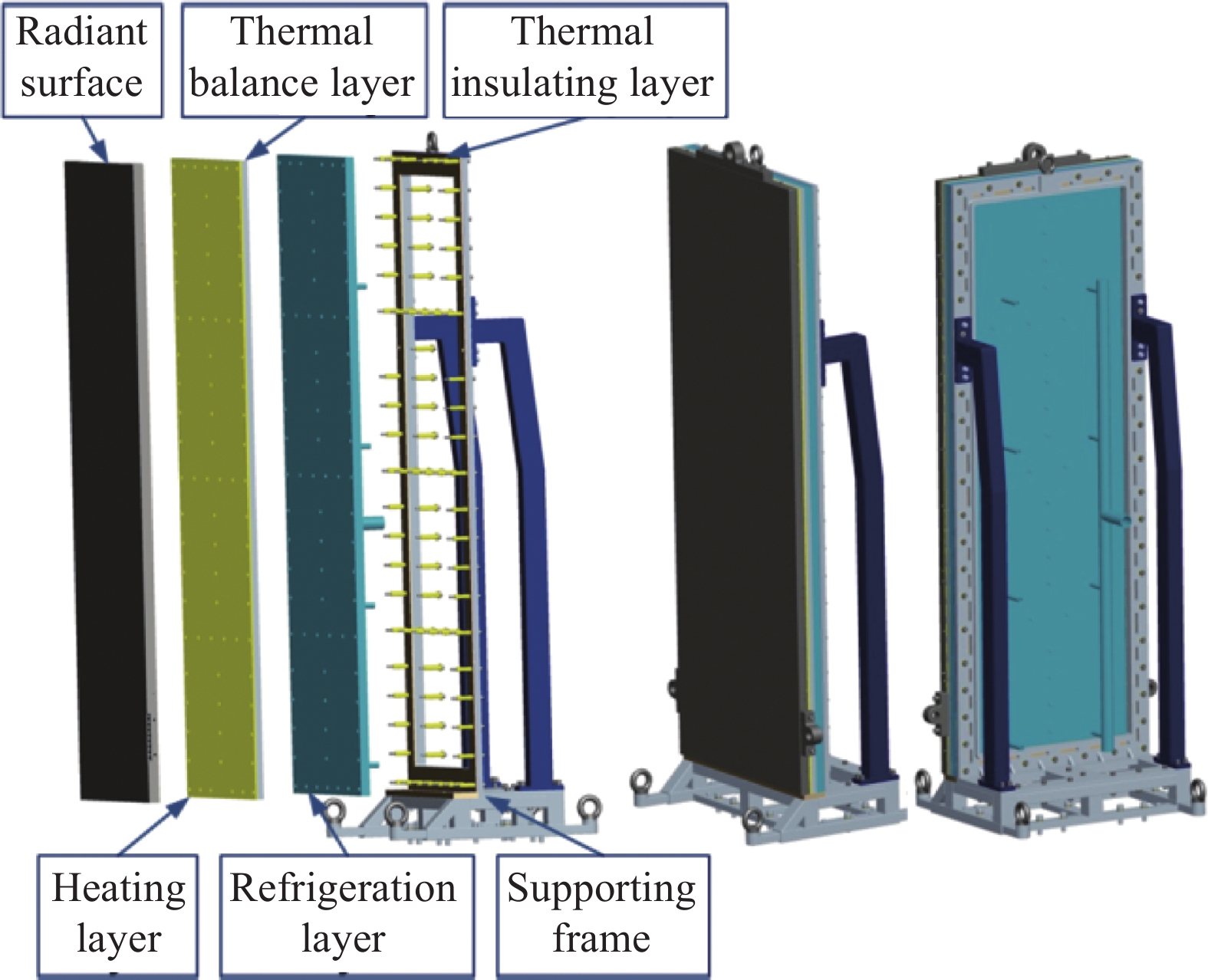
  Objective   Infrared calibrators directly determine the detection accuracy of infrared devices as the reference standard for radiation measurement of infrared devices before the satellite launching. More precise infrared calibrators with large surface are required with the development of infrared optical satellites characterized by large aperture, large field of view and high precision, which means the structure of infrared calibrators must keep stable in high and low temperatures to guarantee the high temperature uniformity of the radiant surface, high precision of temperature control and high stability of the system. In the calibration test, the structure thermal mismatch easily occurs because the multilayered structure of infrared calibrators connected with bolts usually includes a variety of different materials and the deformations become unmatched during heating and cooling process for different thermal expansivity, which can reduce the calibration accuracy and increase security risks and test cost. As a result, optimal design and verification of thermal adaptive structure for the infrared calibrator with large surface, wide temperature range and multiple materials were carried out, to solve the problems caused by structure thermal mismatch, including the loose bolts, low cooling rate and bad thermal uniformity at the low temperatures, as well as the compression failure of heat insulating mattress made of glass reinforced plastic at the high temperatures.   Methods   From the two aspects of normal preload regulation and in-plane warping deformation control, the key materials were selected, the assembly parameters were adjusted and the structure parameters were optimized. Simulation analysis and tests were combined to explore the change rules of bolts preload on multilayered structure made of different materials when the temperature changed, at the same time verify the safety and stability of the structure. Finally, the key technical indexes of infrared calibrator were verified by means of heating and cooling tests.  Results and Discussions   The calculations based on the linear elastic theory indicated that the change of preload was controlled effectively by means of choosing Teflon as heat insulation material and stainless steel as bolt material (Tab.1), which provided a smaller relative deformation between bolts and connected members caused by the temperature change. The original preload was applied between 12 N·m to 20 N·m to avoid bolts looseness at −100 ℃ and deformation failure at 140 ℃ (Tab.2). Furthermore, the diameters of mounting holes were enlarged to be greater than 25 mm to reduce the in-plane warping deformation resulting from bolts shearing (Tab.3). The tightening torque test based on multilayered structure composed of different materials discovered the rules that the tightening torque got linear relation with the deformation in the certain range. The elastic deformation occurred at the low temperatures and on the other hand the plastic deformation was more likely to occur at the high temperatures. The axial stiffness of multilayered structure could be improved by repeating heating and cooling process (Fig.4). The simulation result of the whole system suggested that the proportion of bolts with safe and effective connections had reached more than 90% under the high and low temperatures (Tab.3). The stress of bolts at the upper and lower edges of the calibrator changed more significantly than that at other positions and therefore different assembly parameters could be set according to the bolt positions. The heating and cooling test of infrared calibrator showed that the structure was safe and stable with the temperature change, the cooling time was shortened from 30 h to 4 h (Fig.7), and the temperature deviation of the radiant surface at 193 K was improved from −0.8 K/+0.9 K to −0.3 K/+0.4 K.  Conclusions   The optimal design of thermal adaptive structure can significantly increase the cooling rate of infrared calibrator and improve the thermal uniformity of radiant surface at the low temperatures. The difficulties of loose bolts at the low temperatures and compression failure of heat insulating mattress at the high temperatures were overcome at the same time. This study solved the practical problems in the calibration test and the structural safety and stability after optimal design can meet the design requirements. The optimal design methods of thermal adaptive structure can be referred for the same type of products.
Analysis of distributed detection range changes caused by infrared system self-thermal radiation
Li Baoku, Liu Le, Xu Wei, Zeng Wenbin, Hu Haifei, Yan Feng, Cai Sheng
2023, 52(3): 20220417. doi: 10.3788/IRLA20220417
[Abstract](139) [FullText HTML] (20) [PDF 1773KB](69)
  Objective   Detection range is an important evaluation index of infrared system application. Stray radiation is the main factor limiting the detection distance of infrared system, and the irradiance generated by it shows uneven distribution on the focal plane. Currently, the focal plane of the detector is regarded as a whole or the central region is extracted, and the influence factors such as self-thermal radiation and background radiation are calculated on average. The detection distance is obtained by inputting target parameters, and the overall influence of self-thermal radiation on the focal plane is considered in the cold optical design of the system. When the target imaging is in different focal plane regions, the detection range calculated by the above method is not accurate enough, and the pertinence is not strong in cold optical design. To solve the above problems, a detection range calculation formula including the system noise term is established, and a distributed detection distance analysis method is proposed, which is verified by a transmitted infrared optical system.  Methods   Based on the self-thermal radiation and the classical detection range theory, this paper deduces the calculation formula of the detection range of the infrared system including the system noise term, and proposes an analysis method of the distributed detection range. Taking the transmitted optical system as an example, the sensitivity analysis of the influencing factors is carried out. By sub-regional data processing on the detector focal plane, the main influence surfaces corresponding to the detection range are obtained. On this basis, the change of the detection range before and after the low temperature treatment of the main affected surface (cooling from 293.15 K to 173.15 K) was analyzed (Fig.10, 11).  Results and Discussions   Based on the theory of self-thermal radiation and classical detection range theory, a calculation model of detection ability including its own thermal radiation noise is given, and a direct theoretical calculation relationship is established for the influence of the self-thermal radiation on detection ability. When the target imaging is in different focal plane regions, the detection range obtained through traditional calculation is not accurate enough and the pertinence is not strong in cold optical design, and the distributed detection range analysis method is proposed (Fig.1). Under the condition of only considering its self-thermal radiation, a simple partitioning principle is discussed (Fig.2). Taking the transmitted optical system as an example, the main influence surfaces in each area of the focal plane are obtained (Fig.9) through the statistical results of the influence weights of each component's own thermal radiation in different areas (Tab.3). The detection distance of the corresponding main influence region is significantly improved (Fig.10, 11), providing a new idea for the calculation of target detection range.  Conclusions   Based on the theory of self-thermal radiation and classical detection range theory, the detection range formula directly related to the noise item of infrared optical machine system is obtained, the analysis method of distributed detection distance is proposed, and the principle of focal plane partitioning under the influence of self-heat radiation is given, and a transmitted infrared optical system is analyzed with this method. Under the premise that only the influence of self-thermal radiation is considered and the target is an ideal point target, the variation trend of detection distance along with the irradiance of image plane is given. Then, the focal plane of detector is divided into regions to obtain the irradiance ratio of different regions. Through the radiation amount generated by the surface light source of different components in different focal plane areas, the influence weight of each component self-thermal radiation in different areas was calculated, and the main influence surface of each area was obtained. On this basis, lens 7 and lens 3 were respectively treated with low temperature (293.15 K cooling to 173.15 K), and the maximum increase of detection distance in the main affected areas was 17.03% and 43.32%, with obvious improvement. It can be seen through the example verification that the proposed distributed detection range analysis method can be used as the basis for the calculation of distributed detection range and the design of cold optical index of infrared system after determining the corresponding partition principle according to the analysis environment and analysis conditions.
Development of high precision CO2 detection system based on near infrared absorption spectroscopy
Li Hengkuan, Piao Heng, Wang Peng, Jiang Yankun, Li Zheng, Chen Chen, Qu Na, Bai Huifeng, Wang Biao, Li Meixuan
2023, 52(3): 20210828. doi: 10.3788/IRLA20210828
[Abstract](177) [FullText HTML] (95) [PDF 1469KB](73)
  Objective   Crustal movement will discharge CO2 and other gases to the surface, and the surface concentration of CO2 near the fault zone will be abnormal before the earthquake. High-precision measurement of CO2 gas near the seismic zone can provide important help for the analysis of earthquake precursors. At present, the main methods for measuring CO2 concentration include non-dispersive infrared analysis technology, electrochemical technology, chromatographic analysis technology, etc. However, the above methods generally have the disadvantages of being easily disturbed by its background gas, low accuracy, and unable to achieve real-time monitoring. Tunable diode laser absorption spectroscopy (TDLAS) technology has the advantages of not being disturbed by its background gas, high accuracy, and real-time monitoring. In recent years, it has become a research hotspot at home and abroad and has been widely used in the field of gas detection. In this paper, a high-precision CO2 detection system is developed by using tunable diode laser absorption spectroscopy technology.  Methods   In this paper, a high-precision CO2 detection system for seismic monitoring is established. The tunable diode laser absorption spectroscopy technology is adopted, and the wave number 4 978.202 cm−1 is selected as the absorption spectral line of the CO2 detection system (Fig.1). A multi-channel unit with an effective optical path of 40 m is adopted, and STM32 is used as the control equipment and data processing core equipment (Fig.2). For the detector noise and optical interference fringe noise in the system, Kalman-wavelet analysis algorithm is used to filter and improve the system.  Results and Discussions   The system uses Kalman-wavelet analysis method to eliminate the influence of detector noise and optical fringe interference. The experiment shows that the second harmonic signal to noise ratio of the system at 50 ppmv CO2 concentration is 2.06 times higher than that before filtering (Fig.3). Under different CO2 concentrations (50 ppmv, 300 ppmv, 1 000 ppmv, 4 000 ppmv, 8 000 ppmv), the system error is 2.57%-2.66% (Fig.4). When the system measures CO2 at 4 000 ppmv concentration, the detection precision reaches 20.9 ppmv (Fig.5). According to Allan variance analysis, the method detection limit (MDL) corresponding to the integration time of about 61s is 5.2 ppmv (Fig.6), which realizes the high-precision measurement of CO2 gas.  Conclusions   This paper develops a high-precision CO2 detection system for seismic monitoring. The system adjusts the current injected into the DFB laser to make its output central wavelength at 2 008 nm and serve as the detection light source of CO2. In order to improve the lower detection limit of CO2 gas concentration, the system uses a self-developed cylindrical mirror multi-pass cell with an effective optical path of 40 m. The multi-pass cell can work stably in the temperature range of 0-40 ℃ and the pressure range of 1.333-101.325 kPa to ensure the reliability of the system in the field measurement process. The system control TEC realizes the temperature control of the controlled object, and the control precision of the temperature control system in the laboratory can reach 0.01 ℃. The Kalman-wavelet analysis algorithm is used to filter the system noise, and the frequency of optical fringe interference in the frequency domain is similar to that of cosine wave in the time domain, so as to separate it and remove the optical fringe interference. The experimental results show that the accuracy, precision and the method detection limit of the system are improved after filtering. The system combined with this method can make the geochemical gas measurement have a broader application prospect and provide important help for the accurate analysis of earthquake precursors.
Research on atmospheric transmission calibration method of infrared target simulator
Zhang Xinyi, Chen Zhenlin
2023, 52(3): 20220378. doi: 10.3788/IRLA20220378
[Abstract](194) [FullText HTML] (45) [PDF 2672KB](47)
  Objective   The infrared radiometer is an important device for the calibration of the infrared target simulator and is used as a measurement transfer standard during inspections. The primary calibration parameter for the IR target simulator's radiant energy is irradiance, so the role of the IR radiometer is to measure and calibrate its outgoing irradiance. In infrared transmission, the process will be affected by the atmosphere, including two aspects: One is the infrared radiation by atmospheric molecules, aerosol particles scattered or absorbed by the attenuation, the general use of atmospheric transmittance to characterize the degree of atmospheric attenuation of infrared radiation; second is the atmosphere itself emitted by the atmospheric range of radiation will be superimposed on the target radiation. Atmospheric corrections must be made to improve calibration and measurement accuracy.  Methods   An atmospheric transmission calibration method for infrared target simulators is proposed based on a wide dynamic infrared radiometry method based on a constant standard source. In the calibration of the IR target simulator with a horizontal homogeneous atmospheric approach, a network model of atmospheric transmittance and atmospheric range radiation at different wavelengths, temperatures, and distances is developed using the data analysis capability of convolutional neural networks (Fig.2). Based on the encoder-decoder structure, the detector output voltage under three wavelengths is used as the input of the convolutional neural network, and the test data are normalized and input to the encoder in batches for learning and training, with the batch size set to 8 and the test distance input directly in the embedding layer, and the network is trained according to the training process (Fig.3) to obtain the test distance and atmospheric transmittance and atmospheric range, the model of radiation is given as the correspondence between them.  Results and Discussions   A wide dynamic infrared radiometry method based on a constant standard source was used for multiple experiments to obtain multiple detector output voltage values, which were trained using a network model (Fig.2) to obtain network output values of atmospheric transmittance and atmospheric range radiation at different distances (Fig.7). To verify the improvement of IR radiation measurement accuracy, radiation inversion is performed, and the results of radiation inversion under different methods (Fig.9) can be obtained, and the corresponding IR radiation measurement error graph (Fig.10) and specific values (Tab.2) are shown. The experimental results show that the convolutional neural network algorithm based on the encoder-decoder structure can better predict atmospheric transmittance and atmospheric path radiation, the infrared radiometric average error in three bands of the proposed method is 3.0783%, 3.8186%, 5.3452%, which is far lower than the traditional method, reduces the influence of atmospheric transmittance and atmospheric path radiation, reduces the measurement error of infrared radiation, and improves the calibration accuracy.  Conclusions   The atmospheric transmission correction algorithm is proposed for the problem of atmospheric transmission influence using the direct measurement method. Based on the wide dynamic infrared radiation measurement method with a constant standard source, a convolutional neural network algorithm based on an encoder-decoder structure is used to obtain the relationship between atmospheric transmittance, atmospheric range radiation and waveband and test distance, and atmospheric correction is performed for different wavebands and different test distances. Compared with the traditional method, there is no need to use MODTRAN software to calculate atmospheric transmittance, atmospheric range radiation and atmospheric parameters of the measurement experiment environment, which improves the problem of low distance resolution and accuracy of MODTRAN software under close measurement conditions and improves the accuracy of infrared radiation measurement.
Optical devices
Enhancing broadband response of hot-electron photodetectors by Au/TiO2 composite nanostructure
Guo Sitong, Qiu Kaifang, Wang Wenyan, Li Guohui, Zhai Aiping, Pan Deng, Ji Ting, Cui Yanxia
2023, 52(3): 20220464. doi: 10.3788/IRLA20220464
[Abstract](259) [FullText HTML] (45) [PDF 1959KB](46)
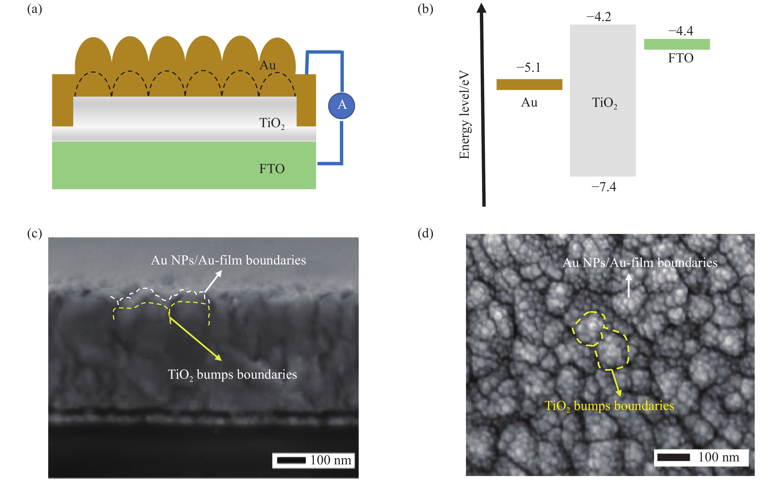
  Objective   Hot electron photodetectors (HEPDs) with wide spectrum responses are promising in the fields of image sensors and optical communications, etc. Metallic micro/nano-structures can efficiently generate hot carriers by exciting surface plasmons. It is helpful to realize low-cost and wide-spectrum response photodetectors when the heterostructures form by combining metallic micro/nano-structures with wide bandgap semiconductors. This approach can also be applied to improve the performance of HEPDs made of other semiconductors. This work contributes to the development of advanced plasmonic devices.  Methods   During the fabrication, the wet-cleaned FTO glass substrates were first subjected to the surface plasma treatment for increasing the work function of FTO substrates. Then, TiO2 and Au films were prepared by radio frequency (RF) and direct current (DC) magnetron sputtering, respectively. In detail, a TiO2 layer with a thickness of 20 nm was deposited onto the FTO substrate, followed by the deposition of an ultrathin Au film with its thickness varying from 2 nm to 8 nm. Then, the as-prepared multiplayer samples were annealed in air at 500 °C. The annealing process could, simultaneously, transform the ultrathin Au film into a layer of Au NPs, and transform the amorphous TiO2 film into its polycrystalline anatase film structure with a rough profile. After that, another thin Au film was deposited onto the annealed samples by DC magnetron sputtering. Here, the thin Au film can act as the transparent electrode with its thickness fixed to 20 nm.  Results and Discussions   The proposed hybrid plasmonic nanostructure based HEPD has an architecture as shown in Figure 1. Here, the TiO2 layer formed a concave-convex nanostructure with a scale of about 100 nm after annealing process, the nanostructure constructed by the Au nanoparticle layer and the conformal Au film used as electrode is for exciting surface plasmons. With the assistance of the Au/TiO2 composite nanostructure, the device has a wide spectrum absorption in the range of 400 nm to 900 nm, and the average absorption efficiency is 33.84%. Therefore, the proposed device can detect the incident photons outside the intrinsic absorption band of TiO2. The responsivity and linear dynamic range of the device under the wavelength of 600 nm separately are 9.67 μA/W and 60 dB (Fig.2). Besides, the corresponding rise/fall response speed are 1.6 ms and 1.5 ms respectively. (Fig.3). The finite element method is also used for simulation calculation, and the electric field distribution diagrams verify that the rich surface plasmon resonances excited in the Au/TiO2 composite nanostructure, which is the reason for realizing the wide spectrum and high efficiency detection (Fig.5).  Conclusions   In summary, we demonstrated a TiO2-based HEPD by incorporating a hybrid plasmonic nanostructure made of Au NPs together with a conformal Au film. Different from other similar approaches that were designed for high-efficiency hydrogen generation in the photocatalysts, a hybrid plasma nanostructure was used in photodetectors for realizing wide spectrum response. With the structural diversity of the hybrid plasmonic nanostructure, different surface plasmon resonances were excited, so that the device can respond to incident photons in a broadband wavelength range, covering UV-visible-NIR. The method of constructing hybrid plasmonic nanostructures has a guidance in developing high-performance optoelectronic devices.
Optical design
Error control of diffractive optical element fabricated by single point diamond turning
Huang Yuetian, Fan Bin, Li Shijie, Liang Haifeng, Cai Changlong, Liu Weiguo
2023, 52(3): 20220504. doi: 10.3788/IRLA20220504
[Abstract](85) [FullText HTML] (10) [PDF 2211KB](46)
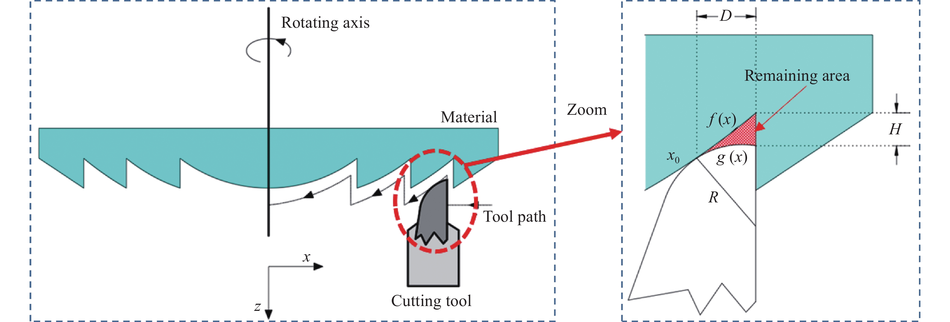
  Objective   Diffractive optical elements are more and more widely used in infrared optical system, which requires higher processing quality of diffractive structure. High-precision diffractive microstructure surface can be machined directly by single point diamond turning. However, the position error and surface quality of diffraction structure have great influence on its optical properties. The diffraction efficiency of diffractive optical element is mainly affected by surface profile quality and surface roughness. The surface profile error and roughness error will produce shadow and scattering effect, which will reduce the diffraction efficiency of diffractive optical element. In order to improve the performance of diffractive optical components, there have been many researches on improving the turning quality of diffractive optical components, but the influence of the surface morphology of the diffraction plane has been ignored. In order to improve the performance of diffractive optical elements, it is necessary to control their turning errors accurately.  Methods   The factors affecting the surface quality of the diffraction element in the process of SPDT processing were analyzed. On this basis, a mathematical model among the ring position error, diffraction surface shape and tool radius was established (Fig.1), which was used to simulate and calculate the relationship between the size of the machining residue area and the turning surface roughness and tool radius. The selection of machining parameters of diffraction optical element turning is guided. Combined with the simulation model and roughness influence parameters, the selection of turning tool radius is guided. It provides technical support for obtaining the high-precision surface topography of diffractive optical elements and is beneficial to improve the imaging quality of diffractive optical elements. Then, based on the simulation results, the machining capability of SPDT on the diffraction surface and the validity of the simulation model are verified by experiments, so as to provide technical support for the high-precision mass production of diffraction optical components.  Results and Discussions   Finally, based on the simulation results, a semi arc tool with a radius of 0.02 mm is selected for machining. The shape error of diffraction element is 292 nm (Fig.6), the maximum position error of diffraction band is 55 nm, the maximum height error is 16 nm (Fig.7), and the roughness is 5.6 nm (Fig.9). Experimental results indicate that the prediction model can guide the acquisition of high precision surface topography of diffractive optical elements, which is beneficial to improve the imaging quality of the optical system. The research results provide technical support for the development of high-precision diffractive optical elements and have a wide range of engineering applications.  Conclusions   Based on the error analysis of single point diamond turning processing diffraction structure, the diffraction element machined by semicircular arc tool has higher machining accuracy and position accuracy. Before the diffraction element is processed, the proper tool radius is selected by using the simulation model of the position error of the annular band of the diffraction structure with a semicircular tool combined with the influence factors of surface roughness. High-precision diffractive optical element can be obtained by controlling the shape of the base plane. According to the design of the diffraction structure plane shape and simulation model, the semi-circular diamond tool with the tool radius of 0.02 mm was selected for turning. The surface shape error of the diffraction element was 292 nm, the position error of the diffraction ring was less than 55 nm, the height error was less than 16 nm, and the roughness was 5.6 nm. The experimental results show that the prediction model can guide the acquisition of high-precision surface topography of diffractive optical elements and improve the imaging quality of diffractive optical elements. The results provide technical support for the development of high-precision diffractive optical elements and have a wide range of engineering applications.
Development of off-axis three-mirror system based on free-form surface
Wang Helong, Chen Jianfa, Huang Haoyang, Cui Zeyao
2023, 52(3): 20220523. doi: 10.3788/IRLA20220523
[Abstract](133) [FullText HTML] (30) [PDF 2726KB](73)
  Objective   With the development and wide application of large area array and high resolution cooled detectors, the requirements for imaging field of view and imaging performance of optical system are becoming higher and higher. Compared with rotationally symmetric spherical and aspheric surfaces, free-form surfaces have higher design degrees of freedom. At present, domestic and foreign scholars mostly use 2-3 free-form surfaces to realize the design of the off-axis three-mirror optical system of free-form surfaces. The optical system configuration is the primary imaging rectangular field of view optical path or the secondary imaging real entrance pupil linear field of view optical path. There are few reports on the design of the secondary imaging real entrance pupil rectangular field of view optical path. To meet the design requirements of wide-band and large-field airborne optical system, a set of off-axis three-mirror optical system for long-wave infrared cooled detector is developed using the form of secondary imaging optical path and XY polynomial free-form surface.  Methods   In this paper, a fast numerical iterative calculation method based on the aberration equation (Fig.1) is presented. A program is compiled using MATLAB to solve the initial structure of the central field of view based on the Tamer T. Elazary quadratic field vector aberration equation. The field of view is continuously increased for calculation, and a better initial structure is finally obtained. The node aberration optimization method is used to balance the coma and astigmatic node characteristics in the full field of view (Fig.3), and gradually reduce the number of free surfaces. The Monte Carlo algorithm is used for tolerance analysis to determine the reasonable tolerance limit distribution (Tab.1). Finally, the interferometer is used to detect the surface shape of the aspheric and free-form surface components machined by turning (Fig.9).  Results and Discussions   The optimized off-axis tri-reflector optical system contains only one free surface (Fig.4), and the efficiency of the cold diaphragm is 100%. Its field of view reaches 5.5°×4.4°, full field MTF is close to diffraction limit. The maximum RMS of full-field wave aberration is 0.06λ and the minimum value is 0.01λ. The average value of wave aberration is 0.03λ (λ=9.11 μm). The imaging quality of the system is good. The system solves the problem of cold aperture matching and the design difficulty of small meridian field of view for the cooled detector. The system is compact without central barrier. And it has technical advantages of wide band, large field of view, high transmittance, etc.  Conclusions   This paper designs an off-axis three-mirror optical system based on the 640×512@24 μm long wave infrared cooled detector. The system adopts the secondary imaging optical path and XY polynomial free surface. The focal length of the optical system is 160 mm, and the working band is 8-12 μm. The F number of this system is 2, and the field of view reaches 5.5°×4.4°. At the same time, this paper also analyzes the tolerance of the reflective free-form surface optical system. The surface shape of the parts was tested after machining. The wavefront test results of the optical system show that the full-field average value of the system wave aberration is 0.067λ (λ= 9.11 μm). The whole system has good imaging quality.
Optical system design of all-time star sensor with large field-of-view
Zhang Qiancheng, Zhong Sheng, Lv Jinsong, Li Xiancheng
2023, 52(3): 20220583. doi: 10.3788/IRLA20220583
[Abstract](264) [FullText HTML] (51) [PDF 2524KB](63)
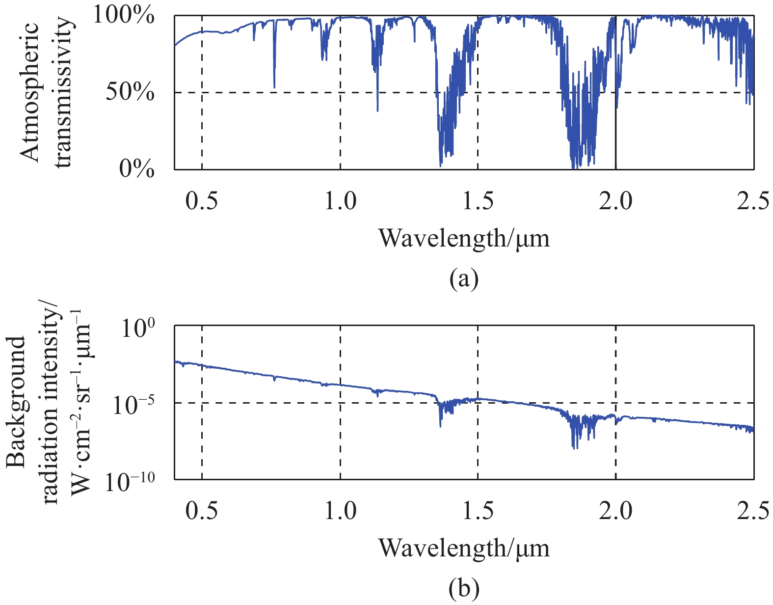
  Objective   Star sensor realizes high-precision star vector measurement or inertial attitude measurement by observing stars, which has the characteristics of high accuracy, strong anti-interference and good concealment performance. Conventional star sensors are mainly used for visible light detection. Due to the influence of sky background radiation, the star detection function can only be realized at night or outside the atmosphere. In order to meet the needs of aircraft, hot air balloons and other near-space carriers to fix the attitude and positioning under all-weather conditions, and to solve the problem of all-time star measurement by star sensors at near-space heights of 6-20 km. Aiming at the problems of small and medium field of view star sensors under all-time conditions that require multiple star observation measurements, tracking axis error has a great impact on accuracy, and large volume and weight, an optical system for all-time star measurement with large field of view at near space heights is designed.  Methods   The star sensor with large field of view optical system can obtain the result of multiple star observations of the star sensor with small field, eliminating the complex tracking axis system, and has great advantages in the accuracy of star measurement, volume and weight, service life, maintainability, and reliability. When designing the optical system, it is necessary to consider the requirements of the star sensor for lightness, miniaturization and wide temperature. According to the working principle and detection ability of the star sensor, the working band of the optical system is analyzed through the atmospheric transmittance and sky background radiation at different heights. The aperture, focal length and field of view of the optical system were analyzed through the star band, number of stars, average number of detected stars, detection probability and detector characteristics, and the working band, F/#, focal length and field of the optical system was clarified. Utilizing achromatic and athermal design, N-LASF31, N-KZFS11/N-PK51, N-LAF2, N-SF66, N-LASF31, N-LASF31, N-LAK8 and other materials are used to realize a transmissive optical system with large field of view and large relative aperture transmission that can adapt to high and low temperature environments.  Results and Discussions   In this paper, the design of a wide-spectrum, large field of view, and large relative aperture all-time athermalized star sensor lens is realized. The structure, the transfer function under different temperature conditions, the vertical axis chromatic aberration, the spot diagram and the distortion diagram of the optical system were analyzed, and all of them met the requirements. A star sensor prototype was built to test the optical system, and the daytime test imaging star was analyzed. The daytime multi-star detection was realized at an altitude of 3 100 m, and the 2 Mv star in the H-band could be stably detected one hour before the sun set.  Conclusions   The test results show that the all-weather star sensor optical system can meet the all-weather multi-star measurement requirements of the wide-field star sensor. The optical system can be adapted to a large target surface star measuring camera to increase the field of view, further increase the number of daytime star measurement, and lower the working altitude of the star sensor. The large field of view all-weather star sensor using this optical system weighs only 1.25 kg. Compared with the all-time star sensor with a small field of view, which weighs more than 10 kg, it has a greater advantage in fitability, which will have positive significance in promoting the application of all-time star sensor technology to the near space field.
Materials & Thin films
Optical communication and sensing
Research on shape sensing performance and reconstruction error of multi-core fiber grating
Zhou Yong, Hu Wenbin, Cheng Pu, Ye Hongrui, Guo Donglai, Yang Minghong
2023, 52(3): 20220485. doi: 10.3788/IRLA20220485
[Abstract](266) [FullText HTML] (45) [PDF 2678KB](43)
  Objective   At present, shape sensing technology based on multi-core fiber grating is mainly divided into two categories, one is the optical frequency domain reflectometry (OFDR) demodulation technology based on the all-same weak grating. The other is multi-core grating or integrated grating shape sensing technology based on wavelength demodulation mode, and the multi-core grating array sensing system based on wavelength demodulation mode has the advantages of small size, high signal-to-noise ratio, fast acquisition speed and high real-time demodulation. In view of the diverse shape sensing needs in the actual application, the multi-core grating array multi-core sensing system using wavelength demodulation can be flexibly configured according to the actual needs of the number and spacing of the grating, which can realize the shape monitoring of the measured object with more flexible sensing distance and more diverse shape change span, which has a wider application prospect. However, because the multi-core grating measurement point cannot be continuously in space, the shape of the blank grating area between the measurement points cannot be obtained, and there is a blind zone of the measurement point. In practical applications, in order to improve the accuracy of shape sensing, it is necessary to study the shape deformation characteristics of the object to be measured, and design a reasonable grating distribution configuration scheme under the premise of taking into account the measurable key points and the full range of measurable areas to be measured.  Methods   Based on the strain sensing characteristics of seven-core fiber gratings, this paper adopts a three-dimensional shape reconstruction method based on homogeneous transformation matrix to reconstruct the shape of two seven-core fiber gratings with different grating spacing, solve the curvature and torsion of the region where the grating measurement point is located by the relative change value of the wavelength of the grating point, and obtain the curvature and torsion of the blank grating region between the FBG measurement points by cubic spline interpolation, and finally integrate the curvature and torsion of all points into the same coordinate system. The three-dimensional shape reconstruction of the object to be measured is realized. In order to explore the influence of grating spacing on shape reconstruction accuracy, the three-dimensional shape reconstruction error under different grating spacing based on this algorithm principle is simulated by algorithm programming, and the experimental verification is completed by building a three-dimensional shape sensing system, and the rationality of the error and simulation error in the experiment is discussed.  Results and Discussions   The simulation calculation selects the raster spacing L of 12.5 cm, 10 cm, 8 cm, 5 cm and 1 cm, and plots the 3D reconstruction curve and the real curve under these raster spacing. Both the simulation assumes that the curvature and torsion measurement error of the gate measurement point is 0. The results show that when the grating spacing L is 12.5 cm, 10 cm, 8 cm, 5 cm and 1 cm, the spatial position error shows a gradual increasing trend with the length of the fiber, and the larger the grating spacing is, the larger the error is. The maximum reconstruction error falls at the end point of the analog length, which is 7.75 cm, 4.35 cm, 2.63 cm, 0.94 cm and 0.25 cm, accounting for 4.8%, 2.7%, 1.6%, 0.6% and 0.16% of the total length (Fig.4). In the experiment, a grating string with a grating spacing of 5 cm and 10 cm was selected to carry out a three-dimensional shape sensing experiment. The experimental results show that the reconstructed three-dimensional shape matches the real shape well (Fig.7). The maximum error at a raster spacing of 5 cm is 1.15 cm, accounting for 1.4% of the total length, and the average error is 0.62 cm, accounting for 0.8% of the total length. The maximum error at a raster spacing of 10 cm is 2.56 cm, accounting for 3.2% of the total length, and the average error is 1.32 cm, accounting for 1.7% of the total length (Tab.1).  Conclusions   Whether it is simulation or experimental verification, the overall trend of error value and relative length of the object to be measured is in line with the trend of linear growth. The maximum error points all occur at the end point. By establishing the variation relationship between the raster spacing and the slope of the linear fit, the correspondence between different raster spacing and the 3D reconstruction error can be explored. According to this relationship, the three-dimensional shape reconstruction error of any grating spacing and any length of optical fiber under similar shapes can be predicted, so that the appropriate grating spacing and demodulation method can be selected in combination with specific application scenarios, reasonable allocation of measurement point resources, and improvement of detection performance in a lower cost range.
Structural design of bending-resistant all-solid fiber with large mode field
Yang Song, She Yulai, Du Hao, Zhang Wentao, Rong Jianfeng
2023, 52(3): 20220551. doi: 10.3788/IRLA20220551
[Abstract](234) [FullText HTML] (39) [PDF 3433KB](25)
  Objective   Compared with traditional solid-state lasers and gas lasers, high-power lasers have a series of advantages such as high stability, flexibility, good beam quality, and energy concentration. In recent years, the output power of fiber lasers has increased to 10 kW. There are important applications in mechanical, medical, communication, sensing, and other fields. However, fiber lasers are usually limited by nonlinear effects such as stimulated Brillouin scattering, stimulated Raman scattering, and four-wave mixing with increasing output power. The massive intensity of the optical field inside the high-power fiber laser usually causes specific damage to the fiber core. Traditionally, the method to avoid core burning is to enlarge the effective mode field area by increasing the fiber diameter. However, it leads to an increase in the output modes and generates mode competition to compromise both the output quality of the beam and bending resistance. Therefore, it is necessary for fibers to achieve a large mode field area with the single-mode operation. For the purpose, a novel fiber with a large mode field area, low bending loss and symmetric is designed in this paper.  Methods   A novel fiber with a large mode field area, low bending loss and symmetric structure is designed in this paper. The proposed fiber consists of a trapezoidal refractive index ring in the core and a multi-trench in the cladding (Fig.1). COMSOL Multiphysics commercial software based on the full vector finite element method is chosen to study the bending properties of the designed fiber. Mapped mesh and free triangle mesh are used to mesh the proposed structure (Fig.2). The bending loss and single-mode operation are used to evaluate the bending properties. The numerical simulation was carried out by changing the fiber related structure, and the optimal structure is verified by thermal load.  Results and Discussions   The bending loss and electric field mode distribution of trapezoidal refractive index ring, rectangular refractive index ring and triangular refractive index ring are compared and analyzed. The experimental results show that trapezoidal refractive index ring has more advantages (Tab.1, Fig.7). The structure of multi-trench in the cladding limits the mode field in the core of fiber. When the number of trenches is greater than 2, the mode field area basically remains the same (Fig.8, Fig.9). The results show that when the wavelength is 1 550 nm and the bending radius is 20 cm, the bending loss of fundamental mode is only 0.056 868 dB/m, while that of high order modes is 3.58 dB/m. The mode field area is 2 313.67 μm2, which meets the requirements of high-power fiber laser (Fig.6). As the thermal load increases, the bending loss of fundamental mode, high order modes and effective mode field area all decrease. When Q is 9.5 W/m, the bending loss of high order modes is less than 1 dB/m, at which time the fiber cannot achieve the single-mode operation (Fig.10).  Conclusions   A novel bending-resistant fiber with large mode field area is proposed. The effects of different structural parameters on bending properties and mode properties are analyzed by the full vector finite element method. The trapezoidal refractive index ring as a resonant ring can fully couple with modes and filter out high order modes, which is beneficial to obtain a larger mode field area. The increase in the number of trenches in the cladding enhances the effective refractive index difference between the core and the cladding, which reduces proposed fiber bending loss. The results show that at a wavelength of 1 550 nm and a bending radius of 20 cm, the bending loss of fundamental mode is only 0.056 868 dB/m and the bending loss of high order modes is 3.58 dB/m, with a loss ratio of 63 and a mode field area of 2 313.67 μm2 for single-mode operation. The effects of different thermal loads on fundamental mode, high order modes and effective mode field area are analyzed. When the thermal load Q is less than 9.5 W/m, proposed fiber can achieve a stable single-mode operation. The fiber is insensitive to bending and has a broad development prospect in the field of optical communication devices such as high-power fiber laser amplifiers.
Effect of Ce doping on radiation resistance of erbium-doped fiber for space laser communication
Wen Xuan, Wang Gencheng, Gao Xin, Feng Zhanzu, An Heng, Yin Hong, Wang Jun, She Shengfei, Hou Chaoqi, Yang Shengsheng
2023, 52(3): 20220871. doi: 10.3788/IRLA20220871
[Abstract](183) [FullText HTML] (33) [PDF 1667KB](29)
  Objective   Space laser communication has the advantages of fast transmission speed, large bandwidth and good confidentiality, and is one of the key development directions of future interplanetary communication. Laser communication requires fast enough transmission rate and high enough transmission power, and erbium-doped fiber amplifier with erbium-doped fiber as the core device is widely used as a signal amplifier in the transmitter and receiver of space laser communication. However, erbium-doped fibers are inevitably affected by the irradiation of space particles in space, which can cause a large number of color-centered defects inside the erbium-doped fiber, resulting in a dramatic decrease in the gain capability and slope efficiency of the device, and then affect the smooth implementation of space laser communication missions. Cerium (Ce) doping is considered as an option to suppress the irradiation loss in optical fibers. Ce can be easily doped into SiO2 glass together with Al, and Ce can suppress the formation of color-centered defects in optical fibers by trapping carriers. Further understanding of the radiation-induced absorption mechanism of Ce doped erbium-doped fibers and enhancing the gain performance of fibers in irradiated environments is essential for the development of space laser communications.  Methods   Three kinds of erbium-doped optical fibers, namely, high Ce doped(HCe), low Ce doped(LCe) and non-Ce doped(NCe) fibers were prepared by chelate vapor deposition. The fibers were irradiated at a cumulative dose of 100 krad and a dose rate of 6.17 rad/s using a 60Co irradiation source at room temperature. The effect of Ce doping on the performance of the erbium-doped fibers under 100 krad gamma irradiation was investigated. The changes of the fiber color center defects were analyzed by absorption coefficient, loss, and Electron Paramagnetic Resonance (EPR) spectra before and after irradiation of the fiber. By testing the fluorescence lifetime and gain coefficient of the fiber, verification of Ce doping enhances the irradiation resistance of erbium-doped fibers.  Results and Discussions   The fiber loss and absorption spectra were tested and found that the loss values of all three fibers decreased gradually with the increase of wavelength after irradiation, and the loss changes in the range of 900-1600 nm showed the characteristics of short wavelength and high loss, and it was speculated that there might be higher absorption peaks before 900 nm. Through the EPR test, The paramagnetic defects are mainly Al-OHC, Ge(1), Ge(2) and other Ge/Si related defects, and the EPR test verified that the irradiation loss in the operating band of the fiber is mainly due to Al-OHC, and Ce3+/Ce4+ can effectively reduce the number of Al-OHC and Ge(1)/Ge(2) related defects number. Thus making the absorption of radiation-induced color-centered defects suppressed. The fluorescence lifetime and gain performance tests showed that the fluorescence lifetime was reduced by 1.099 ms for the NCe and 0.578 ms for the HCe, and the gain of the HCe was 4.15 dB higher than that of the NCe after irradiation. This is due to the fact that Ce doping reduces the AL-OHC defects, decreases the irradiation loss in the working band of the fiber, makes the pump light of the fiber more absorbed by rare-earth ions rather than by color-center defects, and improves the irradiation resistance of the erbium-doped fiber.  Conclusions   Ce doping can reduce the number of carriers during fiber irradiation and thus suppress the formation of color-centered defects during fiber irradiation. Three types of erbium-doped fibers containing different ratios of Ce ions were selected to study the radiation damage from both macroscopic gain performance and microstructural changes. The loss spectra and absorption spectra before and after irradiation were tested, and it was assumed that the main cause of irradiation loss was the trailing of the color-centered absorption peak before 900 nm in the infrared band. Through the EPR test, it was found that the irradiation loss of fibers with high Ce content is smaller and less color-centered defects appear. The analysis is due to the opposite change induced by the valence state of Ce3+/4+ which tends to keep the balance of the ratio of Ce3+ and Ce4+ ions in the glass, The fluorescence lifetime test before and after fiber irradiation shows that the samples with less change in fluorescence lifetime have stronger irradiation resistance, and Ce doping can suppress the shortening of fluorescence lifetime of erbium-doped fibers, which verifies that Ce doping can effectively improve the irradiation resistance of erbium-doped fibers. The gain performance of the fiber before and after irradiation shows that Ce doping can effectively reduce the number of color center defects in the fiber due to irradiation, which can improve the gain performance of the fiber after irradiation. The results of this study can be used as a reference for the subsequent spatially irradiation-resistant reinforcement technology and space applications of erbium-doped fibers.
Identification of characteristics of slip signal based on fiber Bragg grating flexible sensor
Wang Yan, Cheng Dongsheng, Jiang Chao, Ge Ziyang, Jin Ping
2023, 52(3): 20220587. doi: 10.3788/IRLA20220587
[Abstract](131) [FullText HTML] (27) [PDF 2837KB](24)
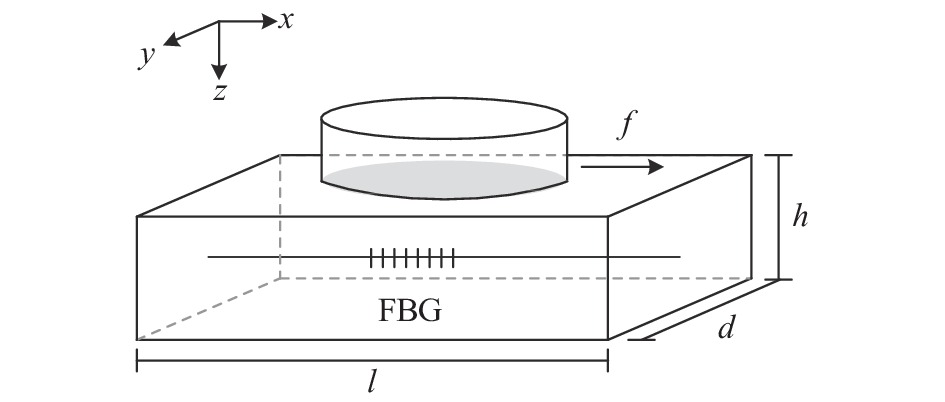
  Objective   The realization mode of robot is developing towards intelligence. In the unstructured environment, bionics need to make self-adaptive decisions on the contact physical quantities (mostly dynamic and continuously changing sliding processes) in the environment. The sliding sensor is the main means for the artificial bionics to realize the perception of the changes in the external physical quantities and make the controller conduct body feedback. Fiber Bragg Grating (FBG) sensor encapsulated by silica gel has the characteristics of high sensitivity, small size, strong anti-electromagnetic interference ability, and is an ideal model for bionic skin. At present, the relevant research at home and abroad has designed FBG flexible sensors with different numbers and array distributions, but the degree of research is still limited, and the analysis of the basic characteristics of the signal at the phenomenal level lacks the necessary quantitative support. In the aspect of feature recognition and analysis of tactile signals, even though some studies have used artificial learning networks to identify or decouple the position, load and other characteristics of tactile signals, the research level is still in the static signal of tactile sensing, and there is a lack of attempts on dynamic and continuous sliding, resulting in deficiencies in the research direction of sliding signal feature recognition. Therefore, this work designs a distributed sensor system based on FBG using PDMS material packaging, and proposes a method to predict the sliding speed and sliding load detected by the distributed grating sensor unit through artificial learning network.  Methods   The sensor array is composed of four gratings (Fig.2), and is packaged into a flexible sensor. An experimental platform is built to collect the slip signal (Fig.3). The principle of FBG wavelength shift during sliding is studied. The sliding signal is compared by EMD decomposition and wavelet analysis, and the signal-to-noise ratio is 15.99 and 16.15, respectively (Tab.1). Set up the sliding experiment system, set the extraction criteria for the sliding signal characteristic values of different speed and load scales (Fig.6), build the sliding sample set, introduce two regression models of random forest and neural network to train and predict the effect.  Results and Discussions   The wavelet function is more conducive to the fidelity of the eigenvalues than the EMD function. The average signal-to-noise ratio coefficient is 0.322 higher. The signal-to-noise ratio and the root-mean-square error of the EMD denoising 8 layers perform well, but the extreme point deviation is large. The SNR and RMSE coefficients perform best when the wavelet decomposition 7 layers, but the waveform still has noise, while the error coefficient and the extreme point of the EMD denoising 8 layers are relatively stable; The magnitude of the FBG center wavelength peak value is related to the pressure load and sliding speed of the slider on the sensor. When the sliding speed and load change, the center wavelength offset curve changes with the sliding characteristic value. In a certain parameter range, the sensor responds well to the change of these two characteristic values and has a relatively linear change rule (Fig.7); The difference between RF and BP regression algorithms in slip speed prediction is not large. RF regression performs better than BP regression in slip load prediction, and basically realizes accurate recognition of slip characteristics (Fig.13).  Conclusions   The experimental results show that the R2 coefficients of the two models are 0.9746 and 0.9681, respectively, and the average error is 5.22% and 4.31%, respectively; In the load characteristic prediction, the R2 coefficients of the two models are 0.9982 and 0.9835, respectively, and the average error is 1.12% and 3.02%, respectively (Tab.3). In the work, a detection and recognition method for the surface slip of distributed FBG flexible sensor is proposed. Through the introduction of artificial regression model, the two characteristics of sliding speed and load of sliding samples under different sliding conditions can be effectively predicted. This research method basically realizes the accurate recognition of the two characteristics of sliding samples, and has certain value in the research of sliding signal in the field of flexible bionic skin sensing.
Fiber Bragg grating temperature insensitive filter based on bimetal structure
Liao Jingjing, Zhu Lianqing, Song Yanming, Xin Jingtao, Lv Zheng
2023, 52(3): 20220505. doi: 10.3788/IRLA20220505
[Abstract](56) [FullText HTML] (11) [PDF 1363KB](25)
  Objective   Fiber optic gyroscopes (FOG) are a new class of instrument capable of accurately determining the orientation of moving objects, which have been widely used in tactical missile guidance, land traffic navigation and aerospace attitude adjustment because of their long service life, easy integration and small size, etc. However, the changing operating temperature in these application fields seriously reduces the average wavelength stability of the broad spectrum light source in the fiber optic gyroscope, thus hindering the further application of the fiber optic gyroscope. To improve the average wavelength stability of the fiber optic gyro wide spectrum light source, this study proposes a method to make a temperature-insensitive filter with a bandwidth of 11.77 nm using a 60 μm ultrashort fiber grating.  Methods   The bimetallic temperature compensation structure (Fig.1) is designed based on the thermal expansion coefficient difference between two metal materials. This structure will compress/stretch the fiber grating with the increase/decrease of temperature and effectively compensate for the wavelength change of fiber grating caused by the thermo-optic effect. The filter is fabricated by combining metal material with fiber grating in two-point packaging, and the effects of the thermal expansion coefficient of the material and the geometric parameters of the filter on the temperature sensitivity of the filter are systematically studied.  Results and Discussions   The results show that the temperature sensitivity of the filter is mainly affected by the thermal expansion coefficient and length of the substrate and the strain transfer beam. The largest adjustable range of L1/L2 (the ratio of the length between two fixed points on the substrate and the length of the filter fiber grating) is achieved as the thermal expansion coefficient difference is −5.8. Besides, the temperature sensitivity of the filter exhibits a negative linear relationship with the value of L1/L2. According to the comparison of the control variable method, it is found that the adjustable range of L1 is larger, and the value range of L1 is 7 times that of L2, which is more conducive to the packaging operation. The base of the bimetal structure is made of brass with a high coefficient of thermal expansion, and the transfer beam is made of aluminum with a low coefficient of thermal expansion. At last, the temperature-insensitive filter with a size of 74 mm×6 mm×4 mm was prepared (Fig.4). When the L1/L2 is 8.39, the base length is 67.1 mm and the filter grating length is 8 mm, the temperature sensitivity coefficient of the fiber grating is 0.15 pm/℃ and the wavelength change is only 4.5 pm in the range of 30-60 ℃, which is more than 60 times lower than that before compensation (Tab.6).   Conclusions   In this study, a bimetallic temperature compensation structure has been successfully designed, and a temperature-insensitive filter with a bandwidth of 11.77 nm has been fabricated using a 60 μm ultrashort fiber grating (Fig.3). The temperature insensitivity filter can effectively improve the temperature insensitivity of the fiber grating, which can be used as a light source filter to improve the average wavelength stability of the light source and is expected to be used in high-precision fiber optic gyroscopes.
Photoelectric measurement
Pose estimation of flying target based on bi-modal information fusion
Li Ronghua, Wang Meng, Zhou Wei, Fu Jiaru
2023, 52(3): 20220618. doi: 10.3788/IRLA20220618
[Abstract](75) [FullText HTML] (10) [PDF 7981KB](36)
  Objective   Flying target pose estimation is the key technology to realize trajectory prediction and missile guidance control. Real-time calculation of missile posture is conducive to judge whether the missile hits the target, timely detect missile failure, and carry out early destruction. The development of information and intelligent technology has led to the improvement of data acquisition accuracy of color camera, laser radar and other sensors, which has formed a technical system of data acquisition by sensors and target position and attitude estimation by relevant algorithms. Most of the existing target pose estimation methods can effectively detect and estimate the target pose. However, there are some problems in the precision prediction and guidance control of missile landing point, such as the inability to quickly and accurately extract and estimate the position and attitude of the flying target in the complex background. Therefore, on the premise of ensuring being real-time, a method for estimating the pose of flying targets based on area array lidar and bi-modal information fusion is proposed.  Methods   Firstly, the coordinate transformation model between the camera and the lidar is established to realize the pixel level matching of the two sensors, fusing the image and point cloud at the same time (Fig.2); Secondly, the ViBe (Visual Background Extractor) algorithm and depth information fusion algorithm are used to extract the moving target in the image, and select the corresponding point cloud according to the image moving target position box (Fig.5); Finally, the PnP (Perspective-n-Point) algorithm is used for rough registration of feature points (Fig.8), to obtain the initial rotation and translation matrix between point clouds. And using I-Kd Tree (Incremental K-dimensional Tree) to accelerate the search of adjacent points, the ICP (Iterative Close Point) algorithm is used for accurate registration, to improve the registration speed.  Results and Discussions   Simulation test and hardware-object simulation test are used to verify the accuracy and stability of the method. The results show that the accuracy of the two-dimensional image object detection algorithm is 97% (Tab.3), and the error classification ratio is 0.0112% (Tab.3). Compared with the traditional ICP algorithm, the accuracy of the pose estimation algorithm is improved by 53.2% (Tab.2), the single time consumption is reduced to 132 ms from 261 ms (Tab.2). Compared with other algorithms, the pose estimation algorithm also has certain advantages.  Conclusions   An algorithm for estimating the pose of flying targets based on bi-modal information fusion is proposed, which can effectively estimate the pose of flying targets on the basis of selecting appropriate parameters. The accuracy of the algorithm is verified by simulation tests. 50 frames of data are simulated and the average error is calculated under the initial condition that the initial object distance between the target and the lidar is 30 m. The simulation results show that the X-axis error is 1.06 mm, the Y-axis error is 4.59 mm, the Z-axis error is 2.07 mm, the Y-axis rotation angle error is 0.63°, the Z-axis rotation angle error is 1.01°, and the solution time is 132 ms. The accuracy of the algorithm is verified by semi-physical ground experiments, and the precision (P) in the image target extraction test is 0.97, the recall (R) is 0.844, and the percentage of wrong classification (PWC) is 0.011 2%. The statistical average error in the pose estimation test is respectively 4.9 mm for X-axis error, 2.7 mm for Y-axis error, 4.62 mm for Z-axis error, 0.97° for Y-axis rotation angle error and 0.89° for Z-axis rotation angle error. The defect that the single source data of the proposed method is difficult to describe the moving target comprehensively can be remedied, and an objective solution is provided for the position and attitude estimation of the flying target. The proposed method is applied to the accurate prediction and guidance control of the landing point of flying targets, and has high military application value.
Long and narrow trajectory measurement system based on centroid matching optimization in close-up scenes
Ai Shuangzhe, Duan Fajie, Li Jie, Wu Linghao, Wang Xiaofeng
2023, 52(3): 20220574. doi: 10.3788/IRLA20220574
[Abstract](156) [FullText HTML] (38) [PDF 2749KB](18)
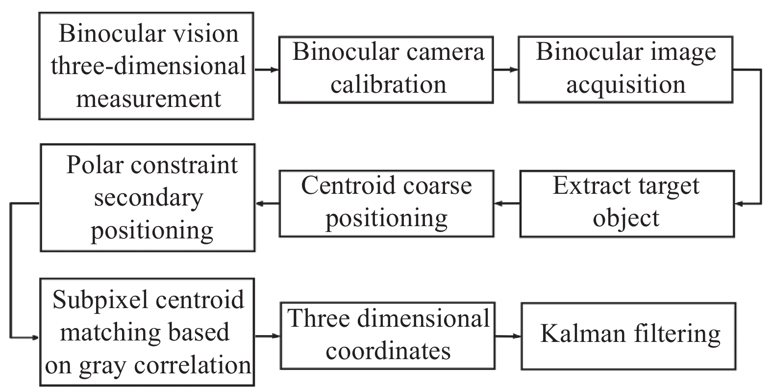
  Objective   Three-dimensional trajectory measurement is a key technology involved in intelligent monitoring, motion analysis and target tracking, which has been widely used in transportation, military and other fields. In recent years, with the rapid development of computer vision technology, imaging equipment and computers are used to replace human eyes and brains to measure the three-dimensional trajectory of target objects with high accuracy. Monocular vision mostly estimates the depth distance of the target in the three-dimensional coordinate system through the proportion of pixel area changes. When the target object rotates and deforms, the depth estimation results are greatly affected. However, binocular vision based on 3D reconstruction mathematical model and polar constraint has the advantages of reliable calculation results and relatively high measurement accuracy in 3D trajectory measurement of flying objects. In the three-dimensional trajectory measurement based on binocular vision, the high-precision matching of binocular homonymous points is the key to improve the measurement accuracy. Especially in the narrow and long space near distance measurement scene for aeroengine safety monitoring, because the binocular camera shoots the target object from different angles, especially when the included angle of the optical axis of the binocular camera is large, the trajectory measurement accuracy of only centroid positioning matching is not high. In order to solve the above problems, a near distance trajectory measurement system in narrow and long space based on centroid matching optimization is developed. In the three-dimensional trajectory measurement based on binocular vision, the high-precision matching of binocular homonymous points is the key to improve the measurement accuracy. Especially in the narrow and long space near distance measurement scene of aeroengine safety monitoring, because the binocular camera shoots the target object from different angles, especially when the included angle of the optical axis of the binocular camera is large, the trajectory measurement accuracy of only centroid positioning matching is not high. To solve these problems, a trajectory measurement system based on centroid matching and optimization is developed.   Methods   First of all, on the basis of only using the centroid method to locate and match the object, the epipolar constraint projection is used to locate the centroid of the binocular. Then, a gray cross correlation method based on distance and method weight is proposed for subpixel matching of binocular centroids. Finally, Kalman filtering is used to correct the 3D reconstructed motion trajectory of the object, in order to improve the measurement accuracy of the trajectory, the three-dimensional trajectory points with large deviation from the ideal trajectory position caused by the unstable centroid position in the extraction of the target centroid are removed from the three-dimensional trajectory. In the laboratory environment, simulate the narrow and long movement space before the bird enters the engine, build a binocular measurement system at the side close position, and carry out the narrow and long trajectory measurement experiment verification.   Results and Discussions   According to the measurement experiment results of different texture target objects (Fig.11, Fig.12, Fig.13 and Tab.1), it can be seen that the depth of the target object's imaging texture has a certain impact on the trajectory measurement accuracy of the measurement system in this paper. Because the gray value distribution of the target object with deeper texture is more abundant, the sub-pixel matching based on gray level cross-correlation has better binocular matching effect, so it has higher measurement accuracy. According to the repeatability experiment results (Fig.14), in the full range of 128 mm, the average trajectory length measurement error of the trajectory measurement system in this paper is 13.14 μm for objects with good texture. The measurement accuracy of track length is about 0.01%, and the straightness error of track is small.   Conclusions   Compared with only using centroid method for coarse positioning and matching, the trajectory length measurement accuracy and straightness of the measurement system are significantly improved, and the high-precision measurement of flying object trajectory in the narrow and long space near distance measurement scene is realized. Based on the error analysis of the measurement results, in the actual measurement, the imaging clarity of the target object texture should be improved by improving the light source illumination and optimizing the optical path design, so as to improve the measurement accuracy of the target object trajectory. The follow-up work direction is to optimize the texture of the target object through image enhancement, improve the trajectory measurement accuracy of the measurement system for the target object with poor texture, and further study the high-precision extraction method of non-rigid body and rotating target matching points, so that the entire measurement system has better stability for the trajectory measurement of different target objects in different measurement scenes.
Design of portable infrared target simulator system
Gao Hongwei, Yang Zhongming, Liu Hongbo, Zhuang Xingang, Liu Zhaojun
2023, 52(3): 20220554. doi: 10.3788/IRLA20220554
[Abstract](291) [FullText HTML] (55) [PDF 2829KB](72)
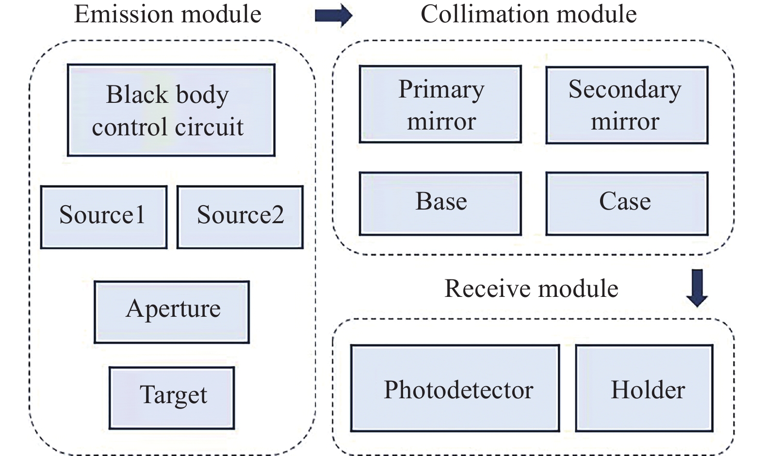
  Objective   Infrared target simulator is an important part of infrared target simulation experiment. When the outgoing pupil of the collimation system coincides with the incident pupil of the detection equipment, it can provide a stable infinitely far simulated target for infrared detection equipment, and the simulation results have the advantages of being accurate, controllable and repeatable experiments, which are used to evaluate the performance and accuracy of infrared detection equipment. It has important applications in radar testing, infrared guidance, infrared tracking, etc. With the development of photoelectric detection equipment sensor integration and miniaturization, multi-band sensors have become the standard configuration of most photoelectric detection equipment. Due to the changes in the debugging environment and the use of the environment, it is necessary to adjust it frequently, but most of the target simulators in the laboratory are only equipped with a single-band light source, large size is not convenient to carry. Therefore, it is necessary to establish multi-band and small-sized portable target simulators to meet the needs of different usage environments. For this purpose, an off-axis reflective infrared target simulator system is designed in this paper.  Methods   A portable infrared target simulator system is built in this paper. A 110 mm aperture parallel light tube of reflective structure was chosen as the collimation system (Fig.2). The optical-mechanical thermal integration analysis of the system was performed to determine the deformation variation of the primary and secondary mirrors and mechanical structure caused by temperature difference (Fig.8). The self-collimating interferometric detection method was mounted using a Zygo interferometer (Fig.11), and the mounting results were judged by the PV and RMS value results of the face shape measurement of the standard plane mirror (Fig.13).   Results and Discussions   The portable infrared target simulation system was mounted using self-collimating interferometry, with PV value of 0.356λλ=632.8 nm)and RMS value of 0.047λ (Fig.13), which is better than λ/20, and the results are excellent and meet the usage requirements. The results of Zernike coefficient analysis shows that the system aberrations are mainly out-of-focus, tilt and higher order aberrations of more than 5 levels (Tab.5), and the adjustable target disc is designed to compensate and improve the imaging quality. A portable infrared target simulator system is built in the laboratory to test the optical path and verify the imaging function of the system. The infrared camera and head were placed at a distance of 10 m from the system, and the imaging results are shown (Fig.14). The targets of different shapes can be clearly identified, and the imaging function of the system has completely satisfies the demand of simulating targets at infinity.  Conclusions   A portable infrared target simulatot system with working wavelengths of 3-5 μm and 8-14 μm is designed. The system is characterized by simple structure, adjustable wavelength, rich target and clear and stable imaging. The wavefront quality of the system was analyzed using Zemax software, and the PV value of the central field of view was 0.013 2λ and the RMS value was 0.003 8λ in the 4 μm band, and the PV value of the central field of view was 0.004 4λ and the RMS value was 0.001 3λ in the 12 μm band. An optical-mechanical thermal analysis of the collimation system was performed, and at a temperature difference of 30 ℃, the deformation caused by the mechanical structure of the displacement of the optical element is much larger than the deformation of the primary and secondary mirrors themselves, reaching the order of 10 μm, and the imaging results have obvious out-of-focus errors, which can be compensated for the out-of-focus errors introduced by the temperature change by refocusing the target disc with adjustable three-dimensional position. The imaging function of the system was tested, for different shapes of targets, the system can become a clear and identifiable image, providing a stable simulated target for infrared detection equipment.
Special issue-Advances in single-photon detection technology
Research progress of InGaAs single-photon avalanche focal plane (invited)
Cui Dajian, Ao Tianhong, Xi Shuiqing, Zhang Cheng, Gao Ruoyao, Yuan Junxiang, Lei Yong
2023, 52(3): 20230016. doi: 10.3788/IRLA20230016
[Abstract](818) [FullText HTML] (85) [PDF 2337KB](290)
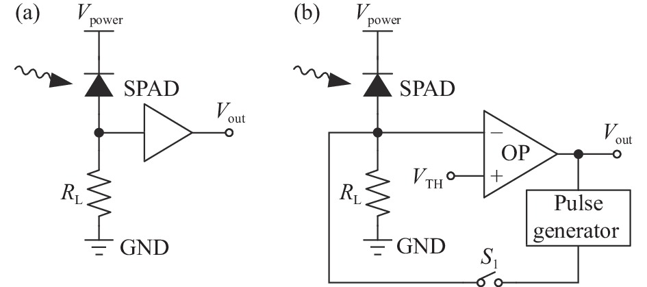
  Significance   Single photon detector is a kind of highly sensitive device that can realize single-photon-level signal detection. Compared with photomultiplier tubes (PMT) with large dark counts rate and large device sizes and superconducting single photon detectors (SSPD) with large-volume refrigeration devices and difficult integration into arrays, the single-photon avalanche photodiode (SPAD) with small size and easy integration into arrays exhibit the advantages of high speed, high sensitivity and high quantum efficiency. InGaAs has the characteristics of direct band gap, large ionization coefficient ratio and lattice constant matching with InP, which is currently the infrared detector material with the best performance in the near-infrared band. And InGaAs/InP SPAD is an ideal detector for active laser detection at 1.06 μm and 1.55 μm. Through the integrated packaging of high-efficiency InGaAs SAPD array and counting CMOS readout integrated circuit (ROIC), the obtained InGaAs SAPD focal plane detector has the characteristics of high sensitivity, high accuracy, small size, and solid-state packaging. The device has been widely used in 3D LIDAR, deep-space laser communication, sparse photon detection and other fields and a research hotspot in the field of single-photon detection in recent years.   Progress   The research progress of InGaAs SAPD focal plane detector can be illustrated by the performance improvement of SPAD array chip and the application progress of ROIC. And the research progress of SPAD array chip includes the research progress of array scale and pixel center distance, crosstalk suppression, photo detection efficiency (PDE) and dark count rate (DCR). The array scale and pixel center spacing of the SPAD array chip determine the spatial resolution of the device. In the early stage, a single CMOS ROIC and a SPAD wafer were electrically connected by face-to-face bonding with epoxy resin, but the disadvantage was that it occupied a large area. Furthermore, by optimizing the device structure and using indium column interconnection, the pixel spacing of the device can be reduced to 50 μm (Fig. 5). In China, the 64×64 InGaAs SPAD focal plane detector developed by Chongqing Institute of Optoelectronic Technology is shown in Fig. 6, which has been successfully extended to 256×64, and the performance parameters are shown in Table1. For a SPAD large array device with high gain characteristics, a very small amount of photons or drift current generated by neighboring pixels is an important factor that generates crosstalk and affects imaging quality. Effective ways to reduce crosstalk include: using planar isolation trench method, setting spectral filter layer and spatial filter layer method (Fig. 7(c)), and pixel isolation technology combined with substrate removal. Among them, the pixel isolation technology can be applied to the manufacture of avalanche focal plane devices to ensure high detection efficiency and effectively suppress array pixel crosstalk. PDE and DCR are parameters that reflect the ability of a device to detect photons correctly. The PDE can be improved by optimizing the parameters of each material layer in the SPAD device structure through the established mathematical model. And DCR can be reduced by improving the quality of the epitaxial material. InGaAs SPAD focal plane detectors have different application directions such as 3D LIDAR, deep-space laser communication, sparse photon detection, thus there are also different solutions for CMOS ROIC. The Flash laser radar system that detects the laser echo by the SPAD array chip is suitable for the application that needs to accurately quantify the "photon time of flight". At present, the mainstream process node of the CMOS ROIC used for the SPAD array chip is 180 nm, which has the characteristics of low power consumption, high time resolution and high frame frequency. The lidar system using a large array of InGaAs SPAD focal plane detector can realize wide-area topographic mapping and fast imaging with an elevation difference of 1000-2500 m, with a resolution of ten-centimeters-level (Fig. 9). The high-sensitivity InGaAs SPAD focal plane detector with small size and integrated capture, tracking and communication can also be used as a receiver for ultra-long-distance laser communication links. Currently, asynchronous readout circuit architectures are available to meet the requirements of shorter readout times and larger data volumes than lidar in optical communication applications (Fig. 11). The InGaAs SPAD focal plane detector with asynchronous ROIC has realized the two-way laser communication link between the lunar orbit and the ground (Fig. 10), with a highest uplink transmission of hundred-Mbps-level. The avalanche focal plane with high PDE and low DCR can also be used to count the number of photons arriving at each pixel. In order to satisfy the counting function requirements, a readout circuit scheme with a counter is used, including counting overflow bit (Fig. 12), multi-statistical time data superposition, etc.   Conclusions and Prospects   SPAD is a photodetection device with high sensitivity and high temporal resolution. Develop infrared high-speed, low-noise focal plane devices based on the integration of InGaAs APD arrays and CMOS timing/counting ROIC, which can be widely used in single-photon-level signal detection for 1.06 μm and 1.55 μm optical fiber communications. The core of SPAD array chip development is to improve its performance, which requires larger array scale, smaller pixel center spacing, high spatial resolution, high PDE, low DCR, time jitter, and low crosstalk to obtain clearer target information. And CMOS ROIC are developing towards large arrays, small pixels, and multi-functions. At the same time, problems such as dynamic power consumption, bias voltage of deep submicron processes, and total output bandwidth need to be solved. Due to its excellent performance, the InGaAs SPAD focal plane detector is widely used in laser three-dimensional imaging, long-distance laser communication, sparse photon detection and other fields, and will continue to expand its application range in the future.
Linear-mode HgCdTe avalanche photodiode detectors for photon-counting applications (invited)
Guo Huijun, Chen Lu, Yang Liao, Shen Chuan, Xie Hao, Lin Chun, Ding Ruijun, He Li
2023, 52(3): 20230036. doi: 10.3788/IRLA20230036
[Abstract](303) [FullText HTML] (69) [PDF 3567KB](157)
  Significance   Single-photon counting has great application prospects in weak signal detection and time ranging. Since the first photon counting system in the visible spectrum was developed in the 1970s, in order to fully amplify the photon signal and reduce the readout noise of electronic equipments, many groups in the research field are constantly developing and improving the photon counting techniques. Electron multiplying charge coupled devices (EMCCDs) can replace the traditional visible light photon counting system and have higher quantum efficiency. While due to large avalanche noise, accurate acquisition of incident photon number under multiplication is difficult. The excess noise factor of mercury cadmium telluride avalanche photodiode (HgCdTe APD) is close to 1, there is almost no excess noise. Compared with the Geiger mode avalanche photodiodes, the linear mode HgCdTe APD has no dead time and after pulse, does not need to quench the circuit, has ultra-high dynamic range and adjustable spectrum with wide response range. Its detection efficiency and false count rate can be independently optimized. It opens up a new infrared photon band counting imaging application. It is of great value in astronomical exploration, laser radar, free space communication and other applications.   Progress   Raytheon and DRS Technologies in the United States, CEA/LETI Laboratory and Lynred in France, and Leonardo in the United Kingdom have successively realized single photon counting of linear HgCdTe APD detectors. This paper summarizes the technical routes and research status of linear mode photon counting HgCdTe APD detectors in Europe and America. The performance of HgCdTe APDs, photon counting ability and the advantages and disadvantages of detector preparation with three structures, namely, separation of absorption and amplification (SAM), planar PIN type and high density vertically integrated photodiode (HDVIP), are analyzed. Raytheon Company has prepared SAM short-wave HgCdTe APD detectors with hole multiplication mechanism by molecular beam epitaxy (MBE), with gain of 350, photon detection efficiency of more than 95% and operating temperature of more than 180 K. DRS Technologies has prepared an electron-multiplication HDVIP medium wave HgCdTe APD detector using liquid phase epitaxy (LPE) material. The detector can respond in the visible to mid-infrared band from 0.4 μm to 4.3 μm, with the highest gain up to 6100 and the photon detection efficiency greater than 70%. It can realize free space communication of 110 Mbps data transfer. CEA/LETI Laboratory and Lynred Company have prepared PIN-type short-wave and medium-wave HgCdTe APD detectors with electron multiplication mechanism by molecular beam epitaxy or liquid phase epitaxy. The gain of short-wave detector is up to 2 000, the maximum gain of medium-wave is up to 13000, the internal photon detection efficiency is up to 90%, the free space communication of 80 Mbps data transfer is realized, and bandwidth up to 10 GHz is achieved at 300 K and gain of 1. British Leonardo Company has prepared SAM type HgCdTe APD detector with electron multiplication mechanism by metal organic vapor deposition (MOVPE). The detectors were named Selex Avalanche Photodiode HgCdTe Infrared Array (SAPHIRA), the device gain can reach 66@14.5 V, single photon detection efficiency is more than 90%. A 24 μm pitch 320×256 array SAPHIRA detectors were supplied to First Light Imaging Company in France to develop a C-RED ONE camera. The C-RED ONE camera was successfully applied to the Michigan Infrared Combiner (MIRC) for astronomical exploration in the United States, which reduced the system noise of MIRC by 10 to 30 times and greatly improved the signal-to-noise ratio of fringe detection. The research on HgCdTe APD detectors started relatively late in China. The main research institutions include Shanghai Institute of Technical Physics, Chinese Academy of Sciences, Kunming Institute of Physics and North China Research Institute of Electro-Optics. Limited by chip preparation technology and circuit technology of HgCdTe APDs, the ability of photon counting has not been realized at present, but some progress has been made in the development of focal plane at home. The single element, 128×128 array and 320×256 array medium wave HgCdTe APD detectors with PIN structure are developed by Shanghai Institute of Technical Physics, Chinsese Academy of Sciences. The gain of the detectors can reach more than 1000, the gain normalized dark current density is less than 1×10⁻⁷ A/cm2 within the gain of 100, and the excess noise factor is less than 1.5 within the gain of 400. At the gain of 133, the noise equivalent photon number is 12, and the short integration time fast imaging is demonstrated. Bandwidth of single element detector is up to 300-600 MHz. The single element and 256×256 array medium wave HgCdTe APD device with PIN structure are developed in Kunming Institute of Physics. The gain of the single element detector can reach more than 1 000. When the bias voltage is less than 8.5 V, the average gain normalized dark current of focal plane is 9.0×10⁻¹⁴-1.6×10⁻¹³ A, and the excess noise factor F is between 1.0 and 1.5.  Conclusions and Prospects   In China, HgCdTe APD devices with planar PIN structure are mainly developed, and the technical path is basically the same as that of France. Therefore, our country can learn from the successful experience of CEA/LETI Laboratory and the business model of Lynred Company, and continue to promote research on HgCdTe APD detectors in order to reach the international advanced level as soon as possible, and realize single-photon detection and photon counting application.
Advancement of shortwave infrared single-photon detectors (invited)
Shi Yanli, Li Yunxue, Bai Rong, Liu Chen, Ye Haifeng, Huang Runyu, Hou Zepeng, Ma Xu, Zhao Weilin, Zhang Jiaxin, Wang Wei, Fu Quan
2023, 52(3): 20220908. doi: 10.3788/IRLA20220908
[Abstract](426) [FullText HTML] (36) [PDF 3486KB](251)
  Signifacance   InP/InGaAs shortwave infrared single-photon avalanche diodes (SPADs) have proved to be the most practical tool for the detection of near-infrared single-photon because of their small volume, near-room-temperature operation, and ease of integration and fabrication of a focal plane array based on the conventional semiconductor manufacturing process. They have achieved wide application including quantum secure communication, spectrum analysis, weak signal detection, Light Detection and Ranging (LiDAR), as well as self-driving vehicles considering the eye-safe laser requirement. etc. The further mass application depends on the performance and price of the SPADs, so the issues about the avalanche diode design and processing, as well as the solution are very important for accelerating the practical application. The review and analyses about the advancement of the shortwave infrared SPDs is very essential for both the academic research and application.  Progress   The separate absorption, grading, charge, and multiplication (SAGCM) structure has been used for InP/InGaAs SPADs since it was designed. This ensures the low electrical field in InGaAs absorption layer and high field in multiplication layer, then tunnelling current arising from high electrical field in absorption layer is remarkably suppressed, so the dark counts. Except for the essential material structure design, the electrical field uniformity in the multiplication layer also influences the performance such as the dark counts of the SPADs. The afterpulsing problem is another issue limiting the maximum count rate of the SPD in the current period. Focusing these issues of InP/InGaAs SPADs, solutions for them are concluded from the long-term study of InP/InGaAs SPADs.The high detection efficiency SPADs, room-temperature SPADs, and high count rate SPADs reported in the past decade by various institutions at home and abroad are summarized in detail. The typical performance parameter detection efficiency is improved by increasing the quantum efficiency via integrated absorption enhancement structure, the reported maximum value for 1 550 nm is 60%. The room temperature operation SPADs was carried out by both decreasing dark counts and sine-wave gated-quenching technology. About 20% detection efficiency and kHz dark counts at 293 K are acceptable for the practical application. Besides, the especial promising result for the room temperature SPDs is the reduced afterpulsing owing to the shortened carrier lifetime under the high temperature. The GHz SPDs benefit from the high and narrow sine-wave gate, as well as the simple harmonic wave noise out of the sine-wave gated-quenching technology. The typical performance parameter of high detection efficiency, room-temperature and high count rate InP/InGaAs SPDs are shown (Tab.1-Tab.3).Moreover, the InP/InGaAs SPAD focal plane arrays (FPAs) and the performance are concluded (Tab.4). The issues for the SPAD FPAs are mainly optical and electrical crosstalk between the adjacent pixels, solution such as mesa separation, microlens and optical filter, etc. are applied for decreasing the crosstalk. The clear three-dimensional image coded distance information was presented (Fig.13). The three-dimensional imaging with high sensitivity and long-distance detection ability attracts the enormous application requirement in both military and civil field. Finally, this paper introduces the novel SPDs technology including addition ionization engineering to the SPADs multiplication layer or using InAlAsSb digital alloys materials to further improve the performance. In0.52Al0.48As with smaller noise factor, wider band gap and matching the InGaAs lattice of the absorbing layer is used as the multiplication layer for electron ionization. Multiple layer ionization is applied to SPADs for increasing the ionization rate and detection efficiency.  Conclusions and Prospects   During the last decade the InP-based shortwave infrared single-photon detectors (SPDs) has gained the dramatic progress, the typical detection efficiency of the InP/InGaAs SPADs has been increased from 20% to 30%, and the dark count rate has been reduced to less than kHz. The high temperature SPADs up to room temperature operation, high speed SPADs up to GHz has appeared owing to the improvement of both avalanche diode and quench circuit. The single-photon focal plane arrays of 256×64 have also presented the clear three-dimensional image.The foreign countries including the United States, Switzerland, Italy, South Korea and Japan, etc. have performed long-term research on InP/InGaAs SPADs, and developed commercial self-products. Domestic research groups have successively prepared InP/InGaAs SPAD chips, and the performance is comparable to foreign reports. Furthermore, single-photon detector arrays have made certain progress, but the device format and performance need to be improved. Novel SPDs technology such as low noise factor material and ionization engineering are expected to further improve the performance. The high performance and low cost shortwave SPDs will further facilitate the quantity application including weak signal detection, LiDAR and digital imaging etc.
Key technologies and development trends of SPAD array readout circuit (invited)
Zheng Lixia, Wu Jin, Sun Weifeng, Wan Chenggong, Liu Gaolong, Wang Jiaqi, Gu Bingqing
2023, 52(3): 20220903. doi: 10.3788/IRLA20220903
[Abstract](295) [FullText HTML] (115) [PDF 1253KB](182)
  Significance   In recent years, the Single Photon Avalanche Diode(SPAD) with single-photon detection capability has been widely used in weak light detection fields such as laser radar, quantum communication, fluorescence spectrum analysis and so on because of its advantages of high sensitivity, fast response, strong anti-interference ability and small size. As a new nonlinear device, SPAD detector has complex manufacturing process. In addition, various applications of SPAD array need readout integrated circuits (ROIC) for detecting sensing signals to be matched with them to achieve the extraction and processing of SPAD detector avalanche signals. Various applications have increasingly high requirements for array size, detector signal extraction and processing capabilities. At the same time, the parasitic effect, power consumption, area and other problems caused by large-scale array are becoming more and more prominent, which seriously affects the imaging quality. The design of array-type SPAD readout circuit is facing great challenges.   Progress   The readout circuit of SPAD array is mainly composed of interface circuit and signal processing circuit. The interface circuit realizes the quenching and extraction of avalanche signal, and the switching between the cut-off and the state to be measured of SPAD. It is a dynamic bias circuit. With the expansion of the array scale, it is required to add SPAD anti-bias voltage adjustable circuit in the interface circuit, realize pixel-by-pixel or regionally adjustable bias of SPAD, and SPAD high-voltage breakdown protection circuit. At present, such technology is only used in small-scale, linear array and some applications, but still cannot be realized in the application of large area array. The main difficulty is that complex circuits cannot be used due to the limitation of pixel area. According to the application of SPAD, the signal processing circuit is divided into photon timing circuit and photon counting circuit. The photon timing circuit is used to measure the flight time of photons. In the circuit, the array-type time-to-digital conversion circuit (TDC) is used. Because the arrival time of each pixel is different, each pixel needs an independent TDC, and the circuit power consumption is very high. This is also one of the reasons that limit the scale expansion of SPAD array. A related research team has proposed a TDC sharing structure, such as the Lausanne Institute of Technology in Switzerland, which proposed a TDC sharing structure (Fig.3). At the same time, because the pixel area is not limited by sharing, multi-segment TDC can be used, and the time resolution of the circuit is less than 100 ps. Compared with the photon timing circuit, the structure of the photon counting circuit is relatively simple. It only needs to record the number of photons detected in a frame. The difficulty of this kind of circuit is to effectively adjust the dead time of the SPAD detector to achieve the best compromise between the detection rate and the dark count.   Conclusions and Prospects   With the demand for SPAD large arrays and the development of readout circuits, the following development trends have emerged in relevant readout circuits in recent years: on-chip data storage, multiple echo detection of returned photon events, and free detection mode. With the further development of the application requirements of SPAD array, the readout circuit will integrate more functions, further develop towards the integration of sensing, memory and computing, and finally truly realize single-chip imaging.
Evaluation and application of HgCdTe linear avalanche focal plane devices (invited)
Zhang Yingxu, Chen Xiao, Li Lihua, Zhao Peng, Zhao Jun, Ban Xuefeng, Li Hongfu, Gong Xiaodan, Kong Jincheng, Guo Jianhua, Li Xiongjun
2023, 52(3): 20220698. doi: 10.3788/IRLA20220698
[Abstract](258) [FullText HTML] (29) [PDF 2696KB](117)
  Significance   The HgCdTe linear avalanche focal plane detector has the characteristics of high gain, high bandwidth and low excess noise, and has shown great application potential in the field of aerospace, astronomical observation, military equipment and geological exploration. Based on their own HgCdTe infrared FPA detector technology, Leonardo, Raytheon, DRS and Sofradir have developed HgCdTe APD focal plane devices. The demonstration of active gating imaging, active/passive dual-mode imaging and 3D imaging have been completed, showing attractive application prospect of HgCdTe APD. However, the research on HgCdTe APD detector technology is still at the initial stage in China, and its application is still in the exploration stage due to the lack of evaluation method.   Progress   The parameters of the HgCdTe infrared focal plane array cannot completely cover the characterization of HgCdTe APD. According to the characteristics and application requirements of HgCdTe APD, in order to accurately characterize the performance of HgCdTe APD focal plane devices, it is necessary to introduce parameters such as gain, excess noise factor, noise equivalent photon number and time resolution. The gain of the APD is used to measure the amplification ability to the input, which is defined as the ratio of the response of the device with gain to the response without gain. The test method of the gain is given and the gain for an APD FPA prepared by Kunming Institute of Physics is shown (Fig.1, Fig.2). The average gain of the APD FPA has an exponential relationship with the bias. When the bias is −8 V, the gain of the FPA is 166 and the gain nonuniformity does not exceed 3.4%. The randomness of the carrier multiplication of the APD introduces excess noise, which makes the SNR of the output deteriorate when the input is amplified. Usually, excess noise factor is used to describe the deterioration of SNR, which can be calculated by the ratio of the device output SNR without gain to the device output SNR with gain. It's worth noting that the conditions need to be consistent during the test, otherwise, the change of the bandwidth will cause the test data not to reflect the true excess noise factor level of the device. The result is shown (Fig.1, Fig.3). Similar to noise equivalent temperature difference, noise equivalent photon number (NEPh) is used to evaluate the sensitivity of APD device in active imaging mode, which is mainly determined by the device gain, dark current level, background flux and readout circuit noise. Generally, NEPh refers to the limiting performance of the device, which is generally tested under the non-background limit (the optical current caused by the background flux should be less than the dark current). In the same conditions, the NEPh of APD device in high gain state decreases with the decrease of integration time (Fig.4). Coupling the APD device with the ROIC with timing function, the distance information can be obtained, which can be evaluated by time resolution. The time resolution reflects the minimum time interval of the pulse laser reaching the focal plane which can be distinguished by the APD, representing the minimum distance that can be distinguished. Finally, combined with the application of HgCdTe linear avalanche device and its characteristics, its application in active/passive infrared imaging and fast infrared imaging is discussed in detail, which can be used as a reference for the application of the HgCdTe APD FPA.   Conclusions and Prospects   Firstly, the key parameters that characterize the performance of HgCdTe APD focal plane chip are analyzed. Secondly, based on the characteristics of HgCdTe linear avalanche focal plane devices, the applications of HgCdTe avalanche focal plane devices in active/passive imaging, fast imaging and 3D imaging are discussed. Finally, the future development of HgCdTe avalanche focal plane devices is prospected. With the development of HgCdTe material growth, fabrication of devices, readout circuit design and processing and testing technology, there will be HgCdTe APD focal plane products with better performance, larger area, smaller pixel center distance and higher frame rate, which meet the demands of high-performance detectors in various applications such as 3D imaging, active/passive dual-mode imaging and single-photon detection.
Low-noise GHz InGaAs/InP single-photon detector (invited)
Long Yaoqiang, Shan Xiao, Wu Wen, Liang Yan
2023, 52(3): 20220901. doi: 10.3788/IRLA20220901
[Abstract](286) [FullText HTML] (51) [PDF 1844KB](141)
  Objective  With the development of quantum information science, laser radar and deep space detection, the traditional linear photoelectric detection technology has been unable to meet the needs of sensitive optical signal detection. The single-photon detection technology has gradually become an important research in the fields of weak light detection. InGaAs/InP avalanche photodiodes (APDs) are widely used in near-infrared single-photon detection due to the small size, low power consumption and fast response. The detection rate of most commercial InGaAs/InP detectors is at the level of 100 MHz, which cannot meet the application requirements for high counting rate. Meanwhile, low noise of the APD will bring smaller false counts to the system and further improve the performance. Therefore, a low-noise InGaAs/InP single-photon detector operating at the repetition frequency of GHz was demonstrated. Furthermore, the whole detector is evaluated with the quantum detector tomography technology, providing support for its application in quantum information technology such as quantum communication and quantum computation.   Methods  In order to determine the detection frequency of gating signals, the response bandwidth of the APD is analyzed in the linear mode, and the bandwidth range is calculated to be 1-2 GHz. The spectral distribution characteristics of APD avalanche and noise signals are analyzed in the Geiger mode. It could be figured out that the noise is mainly distributed in the gating frequency and its harmonic frequencies, while the avalanche signal is mainly distributed below 1 GHz. Therefore, a cascade scheme of sine wave gating combined with low-pass filtering is proposed (Fig.3). The detector comprises high-speed gate generation and delay regulation module, temperature feedback control module, etc. Sine wave gating could be precisely controlled from many parameters which include frequency, amplitude, delay in a wide range. Feedback is added in the temperature control module to improve the stability of the detector. In addition, quantum detector tomography (Fig.2) is introduced to calibrate the detector, which is regarded as a "dark box". The positive operator-value measuring matrix can fully characterize the detector, which is obtained from input states and output results. The Wigner function is employed to describe whether the detector has quantum properties at high input photons.   Results and Discussions   Sine wave gating combined with low-pass filtering is designed in the system, and signal-to-noise ratio is over 40 dB. The relationship between the detection efficiency and the afterpulse probability at the frequencies of 1-2 GHz is recorded. When the working rate is 1.5 GHz and the detection efficiency is set to be 20.0%, the afterpulse probability is 6.6% with the dark count rate of only 6.7×10⁻⁷ per gate (Fig.4). At constant detection efficiency of 20.0%, the DC bias voltage of the APD increases with temperature, showing a linear trend. While the afterpulse probability decreases, showing a contracting trend. The dark count rate degrades with the decrease of temperature and the trend is reversed at −30 ℃ (Fig.5), which might be related to high afterpulse or the intrinsic defection of APD. During the 12-hour test period, the detector performs perfectly stable and the variance of detection efficiency is 1% (Fig.8). Quantum detector tomography technology is employed to verify that high background noise does not affect the quantum properties (Fig.7).   Conclusions  A GHz low noise InGaAs/InP detector is designed, and its detection efficiency, false count, saturation count rate and stability are explored. Based on the analysis of the response bandwidth of APD, a cascade scheme of sine wave gating combined with low-pass filtering is determined, realizing a low noise single photon detection below 2 GHz. In addition, quantum detector tomography technology is employed to calibrate the detector and verify its quantum properties. The structure of the detection technology is simple and the detector can run stably in the long term, which provides strong support for the practical application of single photon detector in deep space communication, laser mapping, optical time domain reflection and other fields.
Miniaturized free-running InGaAs/InP single-photon detector (invited)
Jiang Lianjun, Fang Yuqiang, Yu Chao, Xu Qi, Wang Xuefeng, Ma Rui, Du Xianchang, Liu Ming, Wei Ta, Huang Chuancheng, Zhao Yukang, Liang Junsheng, Shang Xiang, Shentu Guoliang, Yu Lin, Tang Shibiao, Zhang Jun
2023, 52(3): 20230017. doi: 10.3788/IRLA20230017
[Abstract](311) [FullText HTML] (49) [PDF 4957KB](134)
  Objective  Single-photon detectors have the highest sensitivity of light detection. The utilization of single-photon detectors in LiDAR system can greatly improve the comprehensive performance of the system. Laser in the second near-infrared region (1.0-1.7 μm) has the advantages of high atmospheric transmittance, weak scattering and weak solar background radiation, which is the ideal working band of aerosol remote sensing and three-dimensional imaging LiDAR system. Therefore, a high-performance miniaturized free-running single-photon detector is designed in this paper.   Methods  The single-photon detector is based on InGaAs/InP negative feedback avalanche photodiode (NFAD), allowing it to operate in the free-running mode (Fig.1). A precise bias circuit and a precise temperature control circuit provide the bias voltage and cooling for the NFAD, respectively (Fig.2, Fig.3). In order to meet the needs of photon time-of-flight measurement for LiDAR system, the time-to-digital converter (TDC) function is realized by FPGA based on carry delay chain (Fig.4). Through the built-in micro controller unit (MCU) with integrated counting rate and afterpulse correction algorithm, it can make real-time correction of TDC data and output via USB interface.   Results and Discussions   The detector has dimensions of 116 mm×107.5 mm×80 mm (Fig.5). The maximum detection efficiency is more than 35% at 1.5 μm (Fig.6), and the time jitter (full width at half maxima, FWHM) is as low as 80 ps (Fig.7). The time measurement accuracy of internal TDC can reach 100 ps. The miniaturized LiDAR product using this single-photon detector can detect up to 15 km with a range resolution of less than 30 m (Fig.8).   Conclusions  The QCD600 series miniature free-running InGaAs/InP single-photon detector provides a compact and real-time data post-processing single-photon detection solution for LiDAR systems in the near infrared band with high efficiency, low noise, low time jitter. In the future, free-running single-photon detector will be developed in the direction of miniaturization using integrated refrigeration technology and ultra-low noise using deep refrigeration technology, which will provide more powerful technical support for LiDAR, QKD and other applications.
Integrated low-noise near-infrared single-photon detector based on InGaAs NFAD (invited)
Dong Yakui, Liu Junliang, Sun Linshan, Li Yongfu, Fan Shuzhen, Gao Liang, Liu Zhaojun, Zhao Xian
2023, 52(3): 20220907. doi: 10.3788/IRLA20220907
[Abstract](203) [FullText HTML] (20) [PDF 1753KB](121)
  Objective  Single-photon detection technology has attracted attention of researchers increasingly in recent years. The development of negative feedback avalanche diode (NFAD) which integrates a quenching resistor for fast quenching has greatly lessened the afterpulsing effects in InGaAs/InP based near-infrared single-photon detectors. Moreover, the integration of the thermal-electric cooler (TEC) with the NFAD has made the detector small in size and low in power consumption. However, the integration of the quenching resistor with large resistance reduces the amplitude of the avalanche current output to tens of μA. Though it can be read out using a broadband pre-amplifier, the long bonding wire of the TEC-integrated NFAD makes it prone to electro-magnetic interference. In addition, the large parasitic inductance and capacitance of the long bonding wire, combined with the low amplitude of the avalanche signal, makes it hard to cancel the noise induced by the capacitive response of the recovery signal of the NFAD, and hence it is difficult to use active-quenching circuits for better performance. Therefore, it is required to design a sophisticated circuit to solve the problems above to facilitate the application of the NFAD-based single-photon detector.   Methods  An integrated free-running InGaAs near-infrared single-photon detector was developed based on negative feedback avalanche diode (NFAD). In order to tackle with the problem that the readout of the avalanche current is prone to interference when using an amplifier, a high-impedance differential circuit without pre-amplifier was proposed for avalanche signal extraction. By introducing a specially designed resistive-capacitive network and signaling, the active-quenching technique was successfully combined with NFAD and was able to work stably. In addition, shielding material was applied to the amplifier-free readout circuitry for further interference shielding. The design above enhanced the quenching performance and stability of the detector at the same time. Moreover, in order to lower the dark-count rate, the circuit and the heat-dissipation structure of the detector was optimized to maximize the thermal contact area, and hence the high heat from the integrated thermal-electric cooler of the NFAD and the high-speed quenching circuit can be quickly dissipated to achieve lower cooling temperature.   Results and Discussions   The performance of the quenching circuit, the thermal design, and the anti-interference were verified through experiments. Waveforms at the inputs of the comparator (in Fig. 3) showed that the performance of the detector without pre-amplifier was stable. The maximum detection efficiency for 1550 nm wavelength reached 33%, and the minimum dead time available was 120 ns at the detection efficiency of 10%, at −50 ℃, where the dark-count rate and afterpulse probability were as low as 890 Hz and 10.6%, respectively. The heat-dissipation performance was good enough to maintain the temperature of the NFAD at −58 ℃ with fan cooling when the ambient temperature was 20 ℃. At −30 ℃, the afterpulse probability was approximately 70% of the value at −58 ℃, at the cost of a higher dark count rate of 13.2 times of the value at −58 ℃.   Conclusions  The proposed amplifier-free avalanche extraction and active-quenching circuit was able to work with the NFAD stably with a threshold of 9 mV, showing an excellent anti-interference performance. The afterpulse probability was as low as 10.6% at 10% detection efficiency, 120 ns dead time, −50 ℃, indicating that the hybrid quenching performance of the active-quenching circuit with NFAD was sufficient for low-dead-time free-running operation of the detector. In addition, good heat-dissipation performance was achieved by the large-thermal-contact-area design, where the temperature of the NFAD reached −58 ℃ with fan cooling at an ambient temperature of 20 ℃. It is indicated that this highly integrated low-noise near-infrared single-photon detector for communication wavelengths is especially suitable for use in the applications where high performance and minimum space usage are required.
Lasers & Laser optics
Review on laser intersatellite link: Current status, trends, and prospects
Li Rui, Lin Baojun, Liu Yingchun, Shen Yuan, Dong Mingji, Zhao Shuai, Kong Chenjie, Liu Enquan, Lin Xia
2023, 52(3): 20220393. doi: 10.3788/IRLA20220393
[Abstract](583) [FullText HTML] (69) [PDF 1361KB](205)
  Significance   The high directionality and short wavelength of laser transmission in space make it a promising direction for the next generation of satellite laser communication. The laser intersatellite communication can achieve high quality-of-service satellite communication with high transmission speed, wide bandwidth, and high security, which can even improve the precision of satellite ranging in space. The establishment of a satellite backbone network with laser intersatellite links can achieve global management and control of satellites, greatly improve its independence from the ground system, and expand the communication capacity. Due to its advantages in improving the survivability, autonomy, mobility and flexibility of satellite networks, the domestic "Star Network", "Hongyan", "Hongyun", "Xingyun" and "Space-Earth Integration" constellations and foreign "Kuiper", "Telesat" and "Starlink" networks have integrated laser intersatellite links as one of its core transmission link methods, laser communication terminals also become one of the standard spacecraft payloads. It is foreseeable that intersatellite communication will continue to develop and transform from the radio wave era to the laser era, which makes the survey on laser intersatellite links meaningful.   Progress   This paper first introduces the technical fundaments, including the link establishment modes, link modulation modes, and wavelengths. The intersatellite laser link establishment mainly relies on three steps of pointing, acquiring, and tracking, comprehensively called PAT system. The link modulation modes include non-coherent and coherent communications. Compared with the non-coherent system, the coherent system has the advantages of high spectral efficiency. For medium and high-orbit satellites that need to carry more complex and sophisticated communication tasks, the laser intersatellite link is mostly modulated by the coherent communication system. Conversely, low-orbit satellite laser communication and deep space exploration projects mainly use non-coherent modulation mode. To reduce the impact of the solar background and solar scattering, the current laser communication mainly considers the selection in the range of 500 nm to 2 000 nm. Since ground industrial-grade laser components mostly use 1 550 nm wavelength laser as the standard preparation, the communication technology can be migrated to the satellite network at a relatively low cost. With the development of technology, the communication systems of various countries are developing in a more compatible direction, that is, compatible with both 1 064 nm and 1 550 nm wavelengths. Countries have successfully carried out a number of on-orbit technology verifications in the field of inter-satellite laser communication, and have entered the stage of large-scale application. The survey finds that the current on-orbit technology verification uses customized laser terminals to meet the specific needs of various tasks. Companies such as Mynaric, Hyperion Tech, Thales Alenia Space, and NICT have begun to launch laser terminal products with higher speed, smaller mass and volume, and lower power consumption. These terminal products can adapt to the universal requirements of similar multi-task. According to the different mission requirements of different orbit heights, this paper summarizes the current development status and plans of laser communication achievements since 2015 (Tab.1). Through the comprehensive survey, this paper reveals the flexibility and modularity trends of laser communication terminals, and four development trends of satellite laser communication: standardization, compatibility, networking, and commercialization. In addition to being used as a carrier for information interaction, laser ranging can obtain more accurate intersatellite ranging values, stronger anti-interference and anti-eavesdropping capabilities compared to traditional RF ranging solutions. The end of this paper surveys on prospects of satellite laser ranging applications, which intends to provide reference to the domestic development and research of laser-based satellite technology.  Conclusions and Prospects   The laser intersatellite link is developing vigorously. At the same time, the mission requirements of the satellite network are complex and diverse. For satellites of different orbits and mission types, the selection of the communication system, wavelength, and access mode of the laser intersatellite link needs to be analyzed in detail according to each situation. The research aims to provide some reference for the design and optimization of laser inter-satellite links in the future. It is expected that building a standardized, compatible, networked and commercialized laser intersatellite link will help maximize space resources and interconnection of satellite networks.
Influence of output mirror free external cavity spectral beam combining structure on feedback efficiency
Jin Zhuang, Li Jing, Jiang Menghua, Liu Youqiang, Qin Wenbin, Cao Yinhua, Wang Zhiyong
2023, 52(3): 20220446. doi: 10.3788/IRLA20220446
[Abstract](171) [FullText HTML] (36) [PDF 1776KB](32)
  Objective   The external cavity spectral beam combining technology has two structures of open loop (without output coupler) and closed loop (with output coupler). The main difference between them is that the wavelength locked feedback beam of each light-emitting unit is different. Among them, the output coupler free external cavity spectral beam combining structure uses the beam returning from re-diffraction along the 0th-order and 1st-order diffraction direction as the feedback light, which avoids the waste of the beam and overcomes many problems of the feedback locking of the −1st order diffraction beam, and realizes the high-efficiency wavelength beam combination. For spectral beam combining technology, the feedback efficiency of the external cavity determines the stability of wavelength locking and even the success or failure of beam combination. Compared with the general closed-loop structure, the output coupler free external cavity spectral beam combining structure can only obtain enough feedback beams to achieve wavelength locking by controlling the parameters of the external cavity, and this external cavity structure is relatively complex, and the feedback efficiency variation caused by some factors in the external cavity are more obvious than the closed-loop structure. Therefore, for this structure, a simulation system is established to study the influencing factors of the external cavity feedback efficiency.  Methods   The efficiency model of output coupler free external cavity spectral beam combining structure is constructed, and the expression of spectral beam combining efficiency is deduced. According to the expression, the length of the external cavity, the telescope filtering system and the "Smile" effect have great influence on the feedback efficiency of this structure. The output coupler free external cavity spectral beam combining structure in Zemax is established, and the level of the feedback quantity of the two diffraction cavities in this system and the change in feedback quantity caused by changing the cavity length, the influence of the 1st-order diffraction cavity added to the telescope system on the feedback efficiency and quality of the combined beam, and the influence of the "Smile" effect on the feedback beam intensity are studied respectively.   Results and Discussions   According to the output coupler free external cavity spectral beam combining simulation system, the 1st-order diffraction light feedback power accounts for 2.73% of the output power, while the 0th-order diffraction light feedback power only accounts for 0.15% of the output power (Fig.3). As the distance of the external cavity increases from 27 mm to 558 mm, the feedback power decreases from 1.76 W to about 1.45 W (Fig.4), and the feedback beam crosstalk will occur (Fig.5); When different telescope filtering systems are inserted into the 1st-order diffraction cavity, the feedback power of the external cavity remains basically unchanged and the size of the slow-axis beam spot remains about 4 mm (Fig.8); The feedback power steadily diminishes and the combined spot size gradually increases as the degree of "Smile" effect rises from 0 μm to 1 μm. The feedback power of the 500-mm long focal length cylindrical lens inserted in the fast axis direction under the impact of the "Smile" effect at 1 μm is essentially the same as that without the "Smile" effect, which lessens the influence of the "Smile" effect on the feedback power.  Conclusions   The factors impacting on the external cavity's feedback efficiency are analyzed using the output coupler free external cavity spectral beam combining efficiency model. The effects of the external cavity length, the filter structure of the telescope, and the "Smile" effect on the feedback efficiency of the 0th-order and 1st-order diffracted beams are studied, respectively, using the output coupler free external cavity spectral beam combining simulation system built in Zemax. The results show that: (1) The feedback beam is dominated by the 1st-order diffracted beam, and wavelength locking of the external cavity is essential. As the length of the external cavity rises, the feedback power falls and the beam crosstalk increases; (2) The telescope filter structure can effectively filter the stray beam with large deflection angle and accurately feed back the beam to the original light-emitting unit; (3) The degree of "Smile" effect has a particularly negative influence on feedback efficiency and output beam quality. Although the "Smile" effect can be lessened by inserting a long focal length cylindrical lens in the fast axis direction, the beam quality after beam combination won't be noticeably enhanced. The research on the feedback efficiency of the external cavity can be used as a guide when designing the parameters for the output coupler external cavity spectral beam combining structure.
Research on laser melting deposition forming process and accuracy of thin-walled hollow bending and torsion structural parts with variable cross-section
Cai Jiaxuan, Shi Tuo, Shi Shihong, Zhang Rongwei, Liu Guang, Wang Yu, Zhuang Rui
2023, 52(3): 20220436. doi: 10.3788/IRLA20220436
[Abstract](175) [FullText HTML] (30) [PDF 4190KB](19)
  Objective   Variable cross-section thin-walled hollow bending and torsion structural parts have been widely used in aerospace, machinery, shipbuilding and other fields, such as propeller structure, hollow blades in steam turbines, etc. These parts generally have the characteristics of twisting and overhanging, free change of section, etc. Its profile is a variable cross-section for bending and torsion, belonging to a relatively complex free surface, which requires high geometric accuracy in production and application. Traditionally, CNC milling, precision casting, special machining and other processing methods are mainly used, but these processing methods have problems of low material utilization, long production cycle and high processing costs, and in some cases can not meet the actual use requirements. Laser melting deposition (LMD) technology is a new rapid prototyping technology, which has the advantages of complex structure of forming parts, near net forming without mold, and simple process. Based on the technology of laser melting deposition (LMD), the laser melting deposition of thin-walled hollow bending and torsion structure with variable cross-section is studied in this paper.  Methods   Variable cross-section thin-walled hollow bending and twisting structural parts are three-dimensionally twisted in space, with the characteristics of twisting, overhanging and free change of cross-section. Based on the technology of laser melting deposition (LMD) with optical powder feeding, this paper proposes the discrete layered method of space trajectory element to complete the forming trajectory planning (Fig.5), and proposes the compensation technology of base point offset of space variable attitude to compensate the position offset of the actual attitude change base point (Fig.10). Finally, the laser melting deposition forming of the bending and twisting structural parts with variable cross-section was realized and the dimensional error was effectively controlled.  Results and Discussions   In view of the difficulties of forming trajectory planning of such complex structural parts, the discrete layered method of space trajectory element is proposed to layer the structural parts and generate discrete deposition units, and each discrete deposition unit is deposited according to the designed path. In view of the error caused by the smooth curve movement of the manipulator using line segment element fitting in the actual forming process, the space variable attitude base point offset compensation technology is proposed to compensate the position offset of the actual attitude change base point in the forming process, so as to realize the effective control of the size error (Fig.13).  Conclusions   Through the above methods, the forming dimensional error is effectively controlled, the forming accuracy is improved, and finally the laser melting deposition forming of thin-walled hollow bending and torsion structural parts with variable cross-section is realized. The dimensional accuracy of the formed structural parts is relatively high, the shape dimensional error is between −0.44% and 1.83%, the average thickness of the structural parts is between 5.9 and 6.19 mm, the microhardness of the structural parts is between 269 and 282.2 HV, and the surface and interior of the structural parts are dense and uniform, without obvious pores, cracks and other defects.
Study on light source of low jitter excimer laser amplifier
Wang Yizhe, Yu Xuehao, Liu Molin, Zhu Nengwei, You Libing, Fang Xiaodong
2023, 52(3): 20220468. doi: 10.3788/IRLA20220468
[Abstract](149) [FullText HTML] (37) [PDF 1938KB](23)
  Significance   The study of ultrashort pulse laser and its interaction with matter is one of the most popular research fields at present. In order to obtain laser pulse output with higher energy and higher quality, it is needed to make continuous breakthroughs in the research on pulse energy and peak pulse power. Compared with the solid-state laser, excimer laser with the inert gas as the gain medium has its unique advantages in the amplification of the deep ultraviolet femtosecond pulses. Using femtosecond laser pulse as the seed light source, the seed source sends the working signal through the signal controller, and the excimer laser amplifier correspondingly receives the trigger signal sent by the signal controller for pulse amplification, which can obtain high power ultraviolet ultra-short pulse laser. However, in practical application, the pulse repetition rate of seed light under the action of signal controller is unstable and time jitter occurs. Therefore, in order to improve the time synchronization between femtosecond seed light and excimer laser amplifier, the effects of three factors, namely, operation repetition rate, working voltage and gas state, on the luminescence delay time and luminescence time temperature drift of excimer laser amplifier with hydrogen thyratron as high voltage switch were studied in this paper.  Progress   The alignment molecular laser amplifier is designed in a low-jitter working mode with the hydrogen brake tube as a high-voltage switch (Fig.1). A thyratron trigger circuit with a jitter less than 4 ns is used to trigger the on-off hydrogen thyratron (Fig.5), which in the external design can produce an external charging signal and light signal circuit board and can get rising along the range of about 5 ns light signal (Fig.4). From the external trigger signal to the excimer light signal there is a certain delay time (Fig.5). Before realizing the low jitter light output, there will be a certain light output delay drift phenomenon in the thermal equilibrium process of the excimer laser amplifier system (Fig.6). In the laboratory, the PLD20 Excimer Laser was used to study the time synchronization characteristics of excimer amplifier, and the influence of laser operation repetition rate (Fig.7), operating voltage and gas state on the temperature drift and thermal equilibrium state (Fig.8) was discussed, which realizes the excimer light pulse signal in low jitter within 5 ns at different repetition frequencies, and provides a reference for the effective synchronous operation of seed light and excimer amplifier laser.  Conclusions and Prospects   A low-jitter excimer laser amplifier system with the hydrogen switch as a high voltage switch is designed. The trigger circuit with a jitter less than 4 ns is used to trigger the hydrogen gate to obtain the light signal along the range of about 5 ns. Experimental results show that the stable delay time increases with the increase of laser repetition frequency under the same operating voltage. The higher the operating voltage is, the greater the increase of the stability delay time becomes. After gas deterioration, the delay time of optical pulse stability decreases. The higher the laser operating voltage and repetition rate is, the greater the delay drift time becomes. After a certain temperature drift, the internal system of the excimer laser reaches thermal balance. Based on the external trigger signal, the excimer optical pulse signal achieves low jitter output within 5 ns at the repetition rates of 5 Hz, 10 Hz and 15 Hz.
Damage effect of pulsed laser on Ta2O5/SiO2 filter film on quartz substrate
Wang Yunzhe, Zhang Luwei, Shao Junfeng, Qu Weidong, Kang Huachao, Zhang Yin
2023, 52(3): 20220482. doi: 10.3788/IRLA20220482
[Abstract](175) [FullText HTML] (25) [PDF 3309KB](40)
  Objective   Studying the interaction process and damage mechanism between optical films and laser is of great significance for clarifying the effect of laser on imaging devices when films is damaged or not, improving the design and preparation technology of imaging devices and anti-laser hardening technology, and laying the application foundation for related industries and national defense. Over the past few decades, optical films have been widely used in high-energy laser systems, and their ability to resist laser damage is critical to the operation of the whole laser system. The first step to improve the film damage threshold is to accurately measure the damage threshold of the films. At present, the main factors affecting the damage threshold of optical films include the physical properties of the film material, the processing technology of optical films and the laser output parameters. Among these factors, the preparation method, processing technology and physical properties of the optical films have certain effects on the damage threshold of the films, but the output parameters of the pulsed laser are decisive. As a key optical component in multispectral cameras, multilayer filter is often designed according to the actual needs of the suitable medium multilayer film. The study of the interaction process and damage mechanism between the multilayer film and pulsed laser is of great significance for the improvement of the design and preparation of the multilayer film and the anti-laser hardening technology of multispectral camera.  Methods   In the experiment, a Ti: sapphire pulse amplification system, EKSPLA picosecond pulse system and Nimma-900 nanosecond pulse system were used to output laser. The laser damage threshold of Ta2O5/SiO2 multilayer films plated on quartz substrate by electron beam evaporation was measured by 1-on-1 test method. The experimental setup diagram for femtosecond, picosecond and nanosecond laser damage to the multilayer films is shown (Fig.2). The metallographic microscopy is used to observe the damage morphology of the film. We aim to analyze the "pulse width effect" of the damage threshold through the morphological method, and to lay a foundation for the subsequent damage mechanism analysis.  Results and Discussions   The results show that laser-induced damage threshold of the multilayer film by the 800 nm femtosecond laser (1.67 J/cm2), 532 nm/1 064 nm picosecond laser (1.08 J·cm−2/1.98 J·cm−2) and 532 nm/1 064 nm nanosecond laser (9.39 J·cm−2/21.57 J·cm−2). The laser-induced damage threshold of the multilayer film by the femtosecond laser is equivalent to that by the picosecond laser, and the laser-induced damage threshold of the nanosecond laser is one order of magnitude higher. The laser-induced damage threshold outside the transmission passband is about twice that of the laser-induced damage threshold inside the passband. It is verified that the relationship between the material surface damage threshold and the laser pulse width obeys the law of under the thermal damage mechanism. Observing the damage morphology, it is found that with the increase of energy density under femtosecond laser, the film material is ionized, which leads to the obvious delamination spalling phenomenon, and the damage region outline is complete and clear. There are significant differences in the size and density of initial damage points and the thermal damage traces in severe damage although films are damaged by defects under nanosecond and picosecond laser.  Conclusions   The damage characteristics of the multilayer film induced by femtosecond, picosecond and nanosecond pulsed lasers are studied, and the damage morphology and mechanism of the filters under different pulse widths are mainly discussed. Different pulse width lasers have different mechanisms of damage to the multilayer film, that is, the damage mechanism of femtosecond laser is mainly the ionization effect. In contrast, the damage mechanism of picosecond and nanosecond laser is mainly thermal effect. It is concluded that the difference of laser damage between picosecond and nanosecond laser is caused by the difference of laser sensitivity to different pulse widths. This study has certain reference value for the application of the multilayer film in laser application system and high power laser system.
Research on linear array scanning lidar and photon signal processing technology based on InGaAs single-photon detector
Zhang Xiaoyu, Wang Fengxiang, Guo Ying, Wang Wenjuan, Luo Yongfeng, Wu Wen, Hou Jia, Jiang Ziqing, Peng Ziqiang, Huang Genghua, Shu Rong
2023, 52(3): 20220474. doi: 10.3788/IRLA20220474
[Abstract](265) [FullText HTML] (35) [PDF 7306KB](82)
  Objective   With the development of the detection system, the photon-counting imaging lidar based on single-photon detection technology has greatly improved the detection sensitivity of the echo optical signal, effectively reduced the demand of the system for laser power, and made it possible for miniaturized, long-distance, high-resolution, and high-precision laser 3D imaging equipment, which is widely used in the field of long-distance ranging and imaging and has become a research hotspot.Since the number of echo photons in long-distance laser detection is only the order of single photons, the detection performance of the detector is highly required. So at present, most photon-counting lidar remote imaging generally adopts the method of area array staring detection or unit micro-mirror scanning to accumulate the fixed target for a long time to improve the signal-to-noise ratio, which is not conducive to real-time dynamic measurement of large-scale and large-range targets.Although there are many schemes using SPAD (Single-photon Avalanche Diode) to carry out ranging and imaging experiments at home and abroad, Si-based SPAD in the visible band is mainly used. Compared with InGaAs/InP SPAD, the dark count, detection efficiency, afterpulse probability, dead time and other indicators are not ideal. In order to achieve higher single-photon detection performance in near-infrared band, InGaAs/InP SPAD mainly adopts gated quenching mode, which is more suitable for the situation where the target distance is known, while not suitable for the situation where the target range is large, and the relevant research on the range measurement and imaging experiment using the active quenching mode InGaAs/InP SPAD of the free-running system is less, which is only at the stage of principle prototype. Therefore, this study proposes a linear array imaging lidar scheme based on InGaAs/InP single-photon detector.  Methods   Aiming at the working requirements of the eye safety band, based on the free-running mode InGaAs/InP SPAD, a set of remote linear array photon-counting lidar scanning imaging prototype system with multiple transceivers is designed, 128 units of InGaAs/InP SPAD are spliced into a linear array arrangement, the working band of the system is 1 550 nm, the laser repetition frequency is 20 kHz and the laser scanning imaging in the horizontal 200° range is realized through scanning in 2 seconds (Fig.3, Tab.5).At the same time, the factors affecting the detection probability of the detector in the sunlight background are analyzed, and the optimal working point of the system is obtained by combining with the active quenching circuit design (Fig.1) and the adjustment of the working temperature and bias voltage. Point cloud filtering and afterpulse preprocessing algorithms are used to reduce the original data rate of a single receiving channel and characterize isolated targets in the scanning field of view (Fig.2).  Results and Discussions   By analyzing the characteristics of afterpulse and noise, it can be seen that the background noise signal, including the background noise and the dark count signal, is randomly distributed in the whole space. With the increase of the number of echo statistics per unit ranging period, the background noise will increase. Behind the light count signal, there are two levels of obvious afterpulse signal, and the afterpulse caused by the dark count will also lead to the increase of the background noise (Fig.5). After the processing of the point cloud filtering and afterpulse preprocessing algorithm, the original data rate of a single receiving channel is reduced from 200 kbps to less than 1 kbps, and the obvious afterpulse signal behind the target point cloud is removed. Compared with recording single echo, recording four echoes in a single ranging cycle can increase the effective data volume by about 5%. After the processing of the imaging algorithm, the system successfully realizes three-dimensional imaging of multi-range targets under daylight conditions, the maximum detection distance is more than 3 km, and the imaging targets are clear (Fig.7).  Conclusions   In this study, a long-distance imaging lidar system based on photon-counting detection technology is designed, and the detection performance of single-photon detector is studied. After that, the noise and after-pulse characteristics, imaging clarity, and other indicators of the lidar are verified by fixed-point ranging experiments and scanning imaging experiments. The experimental results show that the system can successfully detect multi-range target information, and can detect long-distance targets of more than 3 km. The final reconstructed image is clear, and the noise suppression effect is perfect. The system is suitable for three-dimensional point cloud imaging of long-distance targets. However, due to the significant after-pulse effect of InGaAs/InP SPAD, the increase of dark count will seriously affect the detection performance. The afterpulse and background noise can be significantly filtered by point cloud filtering and afterpulse preprocessing algorithm, and the point cloud data can be compressed for subsequent processing.
Polarization lidar system for smoke and dust monitoring and experimental research
Xu Wenjing, Xian Jinhong, Sun Dongsong
2023, 52(3): 20220508. doi: 10.3788/IRLA20220508
[Abstract](104) [FullText HTML] (15) [PDF 2695KB](42)
  Objective   The fires in forests, wetlands, grasslands and other natural areas are characterised by their sudden and destructive nature, and it is important to reduce the damage caused by fires through early detection and fighting. Traditional fire monitoring methods such as manual inspections and cameras do not allow for 24/7, wide-area monitoring, and there is a lag in detecting fires. Therefore, the use of lidar with high precision, high resolution, long detection distance and sensitivity to changes in aerosol particle concentration, etc., can play an important role in the field of smoke and fire monitoring, to achieve early detection and early warning of fire. Researchers have made some explorations in this area. However, for lidar detection distance of 2 km or more, the single pulse energy of the laser was on the order of millijoule, and there is a human eye safety risk for outdoor use. Moreover, the researchers have not given an analysis of the measurement and application in a multi-obstacle environment. Therefore, a polarimetric lidar system with a day and night detection, and detection distance of more than 6 km and the single pulse energy of the laser on the order of microjoule is proposed.  Methods   Laser wavelengths adapted to outdoor long-range detection are obtained through simulations. The lidar scanning strategies are designed for different installation scenarios, for flat environments and for environments with many obstacles, respectively. As the lidar measurement areas are at a certain height from the ground, correction for fire point positioning errors is based on a Gaussian plume model. A portable lidar system with polarization channels was built to further validate the simulation results, scanning control strategies and inversion algorithms through field experiments.  Results and Discussions   By simulating the detection distance of lidar with different wavelengths, the results show that the detection distance of lidar with 1 064 nm wavelength is 1.3-1.4 times of 532 nm wavelength (Fig.2). By optimizing the scanning strategy and algorithm (Fig.4), the influence of fixed obstacles and temporary moving obstacles can be eliminated. In order to avoid obstacles of similar height around the installation site, a certain elevation angle is usually set for the lidar, and the horizontal distance deviation and vertical height measurement deviation resulting from the existence of the detection elevation angle are calculated. When the elevation angle of lidar detection is 2°, the measured height deviation at 6 km is 209.397 m. The Gaussian plume model is used to simulate the soot concentration distribution. When the atmospheric stability is B and the average wind speed is 1 m/s, the high value point of soot concentration distribution at 200 m height is ≥1 km from the ground fire point, it provides a correction basis for accurate location of fire point. Outfield measurements by using 1 064 nm polarization lidar in both mountainous and plain environments can quickly and accurately identify fire points, which demonstrate the feasibility of using lidar for smoke and fire monitoring.  Conclusions   A scanning polarization lidar can rapidly identify fire smoke and dust. The field experiments were conducted in Panshan County, Panjin City, Liaoning Province, around Yanghu Scenic Area, and Guanyin Mountain Forest Park, Dongguan City, Guangdong Province, respectively. The polarization lidar was able to identify the smoke and dust quickly under the open area and multi-obstacle mountainous area. Observational data will be accumulated in subsequent experimental tests to verify the optical properties of various types of soot particles and further improve the identification efficiency.
Method and experiment of laser detection and tracking of ship wake
Zong Siguang, Zhang Xin, Cao Jing, Liang Shanyong, Li Bin
2023, 52(3): 20220507. doi: 10.3788/IRLA20220507
[Abstract](98) [FullText HTML] (12) [PDF 3937KB](47)
  Objective   Ship wake laser detection and tracking is a new method for underwater vehicles to detect, identify and track ships. Due to the cavitation effect of the propeller, the breaking of the sea waves and the large amount of air involved in the waterline part of the ship during navigation, the air curtain belt containing a large number of bubbles, namely the ship wake, has formed at the ship's tail, which has very different optical characteristics from the surrounding water environment. Through the study of the laser characteristics of the ship wake, the characteristics of the ship's navigation path and speed in the ocean can be further judged, and then the precise guidance and damage attack of underwater vehicles such as the detection system can be realized. Ship wake is a dynamic changing environment, and the distribution characteristics of ship wake and bubble target characteristics are different in different ships and different environments. To achieve accurate attack on ships, it is necessary to study the distribution characteristics of ship wake and bubble target characteristics. By simulating the changing trend of echo signals under different ship wake conditions, it provides theoretical and simulation support for the ship wake in lakes, ocean and other outfield tracking and detection.  Methods   The simulation environment is established based on the ship wake distribution characteristics and bubble target characteristics (Fig.1). The Monte Carlo method is used to simulate the multi-scale, wide-number density and large-thickness ship wake bubble group. Through the analysis of the ship wake backscattering echo signal under different conditions, the real state of the detection system under the characteristics of the ship wake target can be effectively simulated. The signal changing trend of the detection system in the search and tracking phase and the echo signal change intensity of different target ships are obtained (Fig.4-7). The experiment of laser tracking and detection of ship wake in lake environment is carried out, and the simulation results are verified (Fig.9-12).  Results and Discussions   Through the in-depth study of ship wake distribution characteristics and bubble target characteristics, the laser backscattering echo characteristics of different bubble size, bubble number density, bubble layer thickness, and bubble distance are verified by simulation (Tab.1,2). Based on the horizontal/vertical distribution characteristics of bubbles in the wake of ships with different tonnage and speed, the detection ability and tracking method of underwater vehicles at different distances from the wake are studied (Fig.3). The outfield lake test of the laser detection prototype is carried out (Fig.8). The detection device is arranged at different depths to detect the wake of large sand carriers and yachts, which realizes the detection of the wake target under dynamic conditions, and verifies the system detection ability of the underwater vehicle at different distances from the wake (Fig. 9-12).  Conclusions   Based on the engineering application of laser detection of ship wakes, the manuscript establishes a simulation environment based on the distribution characteristics of ship wakes and target characteristics, and uses the Monte Carlo simulation method to simulate the multi-scale, wide-number density, and large-thickness ship wakes bubble groups. By summarizing and analyzing the backscattering echo signals of ship wakes under corresponding conditions, the real state of the detection system under the characteristics of ship wakes target can be effectively simulated. It is obtained that when the laser detection system is located under the wake, the bubble echo amplitude of large ships slowly rises, the bubble pulse width significantly broadens, and the closer to the ship target, the more obvious the bubble echo changes. When the laser detection system is in the wake, the bubble echo amplitude gradually decreases and the pulse width gradually narrows. When the laser detection system is under the wake and the detection system is in the wake, the signal changes are opposite. The signal changing trend of small ships is basically consistent with that of large ships, but the echo intensity of wake laser detection is lower. An outfield laser backscattering echo experimental system is built to verify that when the detection system is under the wake, the bubble echo signal changes to a slow increase in bubble amplitude and a significant broadening of bubble pulse width. When the detection system is in the wake, the bubble echo amplitude gradually decreases and the pulse width gradually narrows. It can provide support for ship wake detection in practical engineering applications.
Materials & Thin films
Regulation of ratio of absorptivity to emissivity of composite thermal control coating via orientation of aluminum flakes
Fei Tianhao, Zhang Wenjie, Zheng Chong, Dong Jian, Liu Linhua
2023, 52(3): 20220532. doi: 10.3788/IRLA20220532
[Abstract](108) [FullText HTML] (28) [PDF 5852KB](24)
  Objective   Metal particle pigmented coatings play a vital role in the thermal control of spacecraft. The ratio of absorptivity to emissivity of coating is one of the important properties of thermal control performance. Besides the conventional factors of particle material, size, volume fraction, morphology and coating thickness, particle orientation is also an important factor in the regulation of radiative properties of the coating. It is important to study the regulation method of the ratio of absorptivity to emissivity of the coating for the design of thermal control coating. The orientation of the particles can be adjusted by operating parameters or alignment agents. The effect of particle orientation on the ratio of absorptivity to emissivity of coating is not thoroughly explored yet. Moreover, the scattering in two-flux theory is usually assumed to be isotropic in the literature. Therefore, it is necessary to investigate the regulation of the ratio of absorptivity to emissivity of the coating by flake orientation.  Methods   As the commonly applied heat dissipation coating, the composite coating pigmented with large-size aluminum flakes was studied. The flakes were assumed to be randomly distributed and identically oriented. Due to the limitation of computer resources, it is infeasible to calculate the radiative properties of randomly distributed non-spherical large particles through strict solution of electromagnetic theory. The radiative properties of aluminum flake at different orientation angles were calculated by geometrical optics considering diffraction, and then the radiative transfer of the coating was solved by two-flux theory considering anisotropic scattering. The geometrical optics and the two-flux theory are suitable for the rapid calculation and analysis of the radiative properties of composite coating pigmented with large-size particles. The effects of orientation angle of aluminum flake, volume fraction and coating thickness were investigated.  Results and Discussions   The spectral radiative properties of aluminum flake at different orientation angles were calculated by geometrical optics considering diffraction (Fig.5), which indicated the variation of absorption cross-section, scattering cross-section, and the asymmetry factor of aluminum flake with orientation angle. The spectral absorptivity (Fig.7) and spectral emissivity (Fig.8) of coatings at different orientation angles were calculated by the two-flux theory considering anisotropic scattering, which revealed the trends at different volume fractions and orientation angles. The regulation of the ratio of absorptivity to emissivity of the coating by flake orientation was investigated. The dependence of average absorptivity, average emissivity, and ratio of absorptivity to emissivity of the coating on the flake orientation angle and volume fraction was illustrated (Fig.9). And the dependence of radiative properties of the coating on the coating thickness was also studied (Fig.10). The ratio of absorptivity to emissivity can be effectively regulated by particle orientation, volume fraction, or coating thickness.  Conclusions   The regulation of the ratio of absorptivity to emissivity of the thermal coating by flake orientation was systematically studied by modeling the coating pigmented with randomly distributed and identically oriented aluminum flakes. The results show that with the increase of orientation angle, the absorption cross-section and scattering cross-section of aluminum flake decrease, and the asymmetry factor increases. The ratio of absorptivity to emissivity of coating can be regulated in the range of 0.48-1.69 by adjusting the flake orientation. The average absorptivity and emissivity of the coating increase significantly when the orientation angle of aluminum flakes exceeds 45°, and increase first and then decrease with the increase of the volume fraction of aluminum flake. The ratio of absorptivity to emissivity reaches a minimum value at the orientation angle of around 45°. And the ratio decreases with the increase of the volume fraction of aluminum flakes. The coating thickness has greater effects on the average emissivity and the ratio of absorptivity to emissivity when the orientation angle of aluminum flake is larger. The ratio of absorptivity to emissivity decreases with the increase of coating thickness. The spectral absorptivity and spectral emissivity of the coating are small and vary little with orientation angle when the orientation angle of aluminum flake is less than 45°, and increase obviously when the orientation angle is greater than 45°, and then decrease with the continued increase of orientation angle. This work demonstrates that the ratio of absorptivity to emissivity can be effectively regulated by adjusting the particle orientation, providing a new method for the design and preparation of thermal control coating.
Rapid quantitative analysis of ZnGa2O4(GZO) thin films using picosecond laser induced breakdown spectroscopy
Dong Lili, Gao Qing, Wu Jiasen, Xia Xiangyu, Liu Shiming, Xiu Junshan
2023, 52(3): 20220470. doi: 10.3788/IRLA20220470
[Abstract](156) [FullText HTML] (34) [PDF 1764KB](18)
  Objective   In recent years, with the rapid development of the research on nanomaterials, transparent conductive oxide nanofilms have been widely used in many fields such as flat display, liquid crystal display screen and thin film solar cell due to their good conductivity and high transmittance in visible light range. ZnGa2O4 (GZO) nanofilms are prepared by doping gallium elements in zinc oxide thin films, and its performance is close to that of traditional tin doped indium oxide (ITO) thin films. Radio frequency (RF) magnetron sputtering, as a mature preparation method for thin film materials, has been widely used in scientific research and industrial fields due to its advantages of stability and high film forming quality. However, in the preparation process of GZO thin film materials, changes in magnetron sputtering parameters often lead to differences in the composition ratio, resulting in different performance of the samples. Therefore, it is necessary to quickly analyze the composition ratio of the prepared GZO films, so as to analyze the performance of the sample and optimize the process parameters of magnetron sputtering. For this purpose, an available and effective analytical method was used to achieve the detection of the composition ratio of the prepared GZO films by radio frequency magnetron sputtering at different sputtering powers.  Methods   During the deposition process of the GZO thin film, the sputtering powers affected the composition ratio of the samples, resulting in a difference in the performance of the GZO thin film, such as the transmittance (Fig.1) and optical band gap widths (Fig.2) of GZO films. In this work, the GZO thin films were analyzed by picosecond laser induced breakdown spectroscopy (PS-LIBS), and the critical element concentration ratios of GZO films were quantitatively analyzed.  Results and Discussions   PS-LIBS experimental setup (Fig.3) and the corresponding LIBS spectroscopy of GZO thin film (Fig.4) were shown. Moreover, the plasma temperature and electron density produced by picosecond laser ablation of GZO film were calculated as 5 426.8 K and 4.2×1 016 cm−3, which satisfied the local thermodynamic equilibrium condition (Equ.4) so as to achieve the quantitative analysis. The results obtained by PS-LIBS showed that there is a certain relationship between the optical properties of the GZO thin films and the intensity ratios of the element spectral lines. With the increase of the sputtering power, the Zn/Ga spectral line intensity ratios and the concentration ratios show a consistent change (Fig.8). Taking the Zn/Ga ratio of the key component of the GZO thin films as the main analysis target, rapid quantitative analysis was carried out on the change of the ratios under different sputtering parameters. The calibration curves of GZO thin films were established with the Zn/Ga spectral line intensity ratios and its energy dispersive spectrometer (EDS) values (Fig.9), and the corresponding linear fitting coefficient was greater than 0.99 which showed good fitting results.  Conclusions   In this study, PS-LIBS technology was used to analyze the Zn/Ga component ratios of GZO thin films deposited by RF magnetron sputtering under different sputtering powers. The linear fitting coefficient of calibration curve was up to be 0.998. The calculated plasma temperature (T=5 426.8 K) and electron density (Ne=4.2×1 016 cm−3) ensured the accuracy of quantitative analysis. The Zn/Ga intensity ratios detected by PS-LIBS under different sputtering powers were closely related to the optical properties of the GZO samples. Both the Zn/Ga intensity ratios and atomic content ratios decreased with the increase of sputtering power. Moreover, the corresponding optical band gap widths increased with the increase of gallium content in the GZO thin films, reaching the maximum value at the sputtering power of 95 W. It indicates that the PS-LIBS method has positive significance for the fast performance analysis of GZO thin films with its advantages of fast, real-time, in situ and micro-damage analysis, and it can also achieve real-time optimization of preparation parameters for GZO films deposited by radio frequency magnetron sputtering.