


-
激光探测由于精度高、方向性好、抗电磁干扰能力强,常用于近炸引信实现高精度定距和方位识别[1-2]。周视激光引信能探测360°范围内的目标,测量目标距离、识别目标与引信的相对方位。若将周视激光引信配装于定向战斗部,可在最佳时机向最佳方位起爆战斗部,实现目标的高效毁伤,其中起爆时机和方位的解算结果将直接影响战斗部的毁伤效果[3-8]。与此同时,由于激光探测本身不具备识别目标特性的能力,激光引信探测过程中易受干扰目标的影响,发生“虚警”或误炸。
文中针对脉冲激光同步扫描体制的周视激光引信,基于在探测过程中获取的多个目标探测点的距离和方位信息,建立目标速度模型,通过对目标速度进行估算,以辨别目标真伪。同时综合目标上多探测点信息,预估目标特征几何中心位置,解算引信最佳起爆时间和方位角,使战斗部获得最大毁伤效能。
-
以弹丸发射点
${o_0}$ 为原点,建立大地坐标系${o_0}{x_0}{y_0}{z_0}$ ,${x_0}$ 轴在水平面内沿弹丸发射方向,${y_0}$ 轴铅直向上,${z_0}$ 轴与${x_0}$ 轴、${y_0}$ 轴构成笛卡尔坐标系。以激光探测系统的发射中心${o_m}$ 为原点,建立弹体坐标系${o_m}{x_m}{y_m}{z_m}$ ,${x_m}$ 轴沿弹丸轴线指向其前进方向,${y_m}$ 轴沿弹轴垂直方向指向上,${z_m}$ 轴与${x_m}$ 轴、${y_m}$ 轴构成笛卡尔坐标系。以目标的几何特征中心${o_t}$ 为原点,建立目标坐标系${o_t}{x_t}{y_t}{z_t}$ ,${x_t}$ 轴沿目标轴线并指向其头部,${y_t}$ 轴沿目标轴线垂直方向,${z_t}$ 轴与${x_t}$ 轴、${y_t}$ 轴构成笛卡尔坐标系。若弹丸和目标的俯仰角为
${\beta _m}$ 和${\beta _t}$ ,偏航角为${\psi _m}$ 和${\psi _t}$ ,所有角度以逆时针方向为正,可得三个坐标系之间的转换关系。弹体坐标系到大地坐标系的转换关系为:式中:
$C_0^m$ 表示弹体坐标系到大地坐标系的方向余弦矩阵。大地坐标系与目标坐标系的转换关系为:
式中:
$C_t^0$ 表示从大地坐标系到目标坐标系的方向余弦矩阵。则弹体坐标系与目标坐标系之间的转换关系为:
假设在周视激光引信探测过程中次序接收到目标表面
${F_1}$ 、${F_2}$ 、…、${F_k}$ 点反射的光脉冲信号,并解算出上述各探测点在弹体坐标系中的距离和方位角,从而能够获得各点在弹体坐标系中的三维坐标。图2表示探测点${F_k}$ 在弹体坐标系${o_m}{x_m}{y_m}{z_m}$ 中的位置。
Figure 2. Location diagram of target detection point
${F_{{k}}}$ in missile coordinate system${o_m}{x_m}{y_m}{z_m}$ 图2中,光束倾斜角
${\alpha _t}$ 表示激光束与弹体坐标系${x_m}$ 的夹角,探测点${F_k}$ 到原点${o_m}$ 的距离为${R_k}$ ,方位角φ为原点${o_m}$ 和探测点${F_k}$ 的连线在${y_m}{o_m}{z_m}$ 平面上的投影与${y_m}$ 轴的夹角。根据投影定理和三角形法则,可知探测点${F_k}$ 在弹体坐标系中的坐标$ ({}^{{m}}{{{x}}_k},{}^{{m}}{{{y}}_k},{}^{{m}}{{{z}}_k})$ 为: -
在大地坐标系
${o_0}{x_0}{y_0}{z_0}$ 中激光探测系统探测目标如图3所示。
Figure 3. System detecting target in geodetic coordinate system
${o_0}{x_0}{y_0}{z_0}$ 在图3中,定义激光坐标系
${o_l}{x_l}{y_l}{z_l}$ ,坐标系原点${o_l}$ 与${o_m}$ 重合,激光出射方向为${x_l}$ 轴。激光坐标系${o_l}{x_l}{y_l}{z_l}$ 可以看作先将弹体坐标系${o_m}{x_m}{y_m}{z_m}$ 绕${z_m}$ 轴逆时针旋转${\alpha _t}$ ,再绕${y_m}$ 轴旋转$\varphi $ 形成的,令$C_m^l$ 为激光坐标系${o_l}{x_l}{y_l}{z_l}$ 和弹体坐标系${o_m}{x_m}{y_m}{z_m}$ 之间的方向余弦矩阵,则有:故激光坐标系与弹体坐标系之间的转换为:
联立公式(1),得激光坐标系与大地坐标系之间的转换关系为:
图3中,
${{{r}}_t}$ 为探测点在大地坐标系上的位矢,${{{r}}_{{m}}}$ 为弹体坐标系和激光坐标系原点的位矢,${{{r}}_{mt}} = {{{r}}_t} - {{{r}}_m}$ 为探测点在激光坐标系上的位矢。根据速度的定义,可知在大地坐标系下目标的速度矢量${{{v}}_t}$ 、弹丸的速度矢量${{{v}}_{{m}}}$ 和目标与弹丸的相对速度矢量${{{v}}_{{{mt}}}}$ 分别为:将
${{{{v}}}_{{{mt}}}}$ 在激光坐标系上投影,可得式中:左上标表示其所处的坐标系,其中
根据探测点
${F_k}$ 的回波信号,可得点${F_k}$ 到弹体坐标系原点${{{o}}_{{m}}}$ 的距离${R_{{k}}}$ 。由多个探测点的距离${R_{{k}}}$ ,求解出${}^l{{{v}}_{{{mt}}}}$ 中的第一个元素${}^l{{{v}}_{{{mtx}}}}$ ,即在激光坐标系下弹丸与目标之间的相对速度${{{v}}_{mt}}$ 在${x_l}$ 轴上的投影。由于采样频率较高,相邻探测点探测间隔时间短,可以计算相邻探测点的平均速度代替目标瞬时速度,已知$\left| {{{{r}}_{{\rm{mt}}}}} \right| = {R_k}$ ,可得:式中:
$\Delta {{t}}$ 表示探测相邻点${F_{{k}}}$ 和${F_{{{k}} + {{1}}}}$ 的时间间隔,一般情况下即为探测系统的脉冲周期${T_{{m}}}$ 。为提高目标运动速度的计算精度,通过探测目标上多个相邻点来计算${}^l{{{v}}_{{{mtx}}}}$ 的平均值。令
联立公式(12)~(14),得:
提取公式(15)中的第一个方程:
仅考虑目标做平面运动,其绝对速度矢量为
$^0{{{v}}_t}$ ,而在公式(16)中包含$^0{v_{tx}}$ 、$^0{v_{t{{y}}}}$ 、$^0{v_{t{{z}}}}$ 三个未知量,可联立三个探测点信息的计算方程构成方程组:根据公式(17),通过三个探测点的回波信息即可求解目标运动速度的各个分量,从而计算出目标速度矢量
$^0{{{v}}_t}$ ,采用多次测量求平均的方法可进一步提高测量精度。当弹药被用于攻击某一特定目标时,可预先在周视激光引信中装定攻击目标的速度范围,在激光探测目标过程中,通过目标上多探测点信息估算目标速度,并与既定目标速度范围进行比较,实现真伪目标的辨别,避免引信发生“虚警”或误炸。 -
对于爆破战斗部,为实现最大毁伤效能,应使爆炸最大密度破片恰好攻击目标的易损部位[10]。通常简化认为目标几何中心为其易损部位,则要求引信能够在探测过程中尽可能准确地估计出目标的特征几何中心位置。
在大地坐标系中,系统对目标的探测过程如图4所示。

Figure 4. Diagram of start detection point and end detection point on target surface
图4中的
${F_1}$ 、${F_2}$ 分别表示目标的起始探测点和终止探测点,对应在大地坐标系中的位矢分别为${{{r}}_{t1}}$ 和${{{r}}_{t{{2}}}}$ ,两点间的距离为$\left| {{{{r}}_{t{{2}}}}{{ - }}{{{r}}_{t{{1}}}}} \right|$ ,探测两点的时间间隔为t,则有:公式(18)中L表示目标体的特征长度,由于
$\left| {{}^0{{{v}}_t}} \right|$ 、t和$\left| {{{{r}}_{t{\rm{2}}}}{\rm{ - }}{{{r}}_{t{\rm{1}}}}} \right|$ 均已知,则根据公式(18)即可求解出L,从而计算探测结束时刻目标几何中心点${F_c}$ 的位矢${{{r}}_c}$ :假设弹丸静止时,爆炸后的破片以速度v沿垂直弹轴方向飞散,作用半径为R,且在飞散过程中速度不衰减。探测结束ΔT时间后起爆弹丸,破片与目标交会模型如图5所示。

Figure 5. Fragment and target intersection model. (a) Intersection process of fragments and targets in the geodetic coordinate system; (b) Initiation azimuth in the projectile coordinate system
在图5(a)中点
${M_2}$ 和${M_3}$ 分别为弹丸探测结束和最终起爆位置,${{{r}}_{m2}}$ 和${{{r}}_{m3}}$ 分别表示点${M_2}$ 和${M_3}$ 的位矢,${{{v}}}$ 和${{{v}}_{{m}}}$ 分别表示破片静态飞散速度矢量和弹丸运动速度矢量。考虑弹丸速度,战斗部爆轰后破片作用范围如图5(a)中阴影部分所示,则破片的绝对速度${{{{v}}}_{{h}}}$ 可表示为:如图5(b)所示,起爆方位角
${\alpha _{{m}}}$ 为弹体坐标系中破片静态飞散速度矢量v与${y_m}$ 轴之间的夹角,则有:最佳起爆条件应使弹丸起爆
$\Delta {T_h}$ 时间后破片恰好击中目标的易损部位即其特征几何中心点,此时距探测结束已历经了Δt=ΔT+ΔTh的时间,目标的特征几何中心点的位置为:最佳起爆条件满足:
其中,
联立公式(19)、(23)、(24),得:
式中:
${{{{r}}}_{m{{t}}2}} = {{{{r}}}_{t2}} - {{{{r}}}_{m2}}$ ,表示探测结束时刻的弹目距离,其值可以通过探测点回波脉冲信号直接得到。在大地坐标系下,弹丸速度${{{{v}}}_m}$ 为:公式(25)中,
${{{{v}}}_m}$ 、${{{{v}}}_t}$ 、$\left| {{{v}}} \right|$ 、${{{r}}}_{{{mt2}}}^{}$ 、L可以通过多探测点数据,基于目标速度模型求解,代入即可求解同步扫描周视激光脉冲探测系统的最佳起爆时间$\Delta T$ 、最佳起爆方位角${\alpha _{{m}}}$ 和起爆后破片击中目标时间$\Delta {T_h}$ 。 -
根据上述建立的最佳起爆模型可知,最佳起爆时间
$\Delta T$ 和最佳起爆方位角${\alpha _{{m}}}$ 与弹丸自身俯仰角${\beta _{{m}}}$ 、偏航角${\psi _{{m}}}$ 、速度大小$\left| {{{{{v}}}_{{m}}}} \right|$ 、破片静态飞散速度大小$\left| {{{v}}} \right|$ 、目标速度${{{{v}}}_{{t}}}$ 、弹目距离${{{r}}}_{mt2}^{}$ 以及目标特征长度L有关。 -
假设已知
${\psi _{{m}}} = - \dfrac{\pi }{4}$ ,$\left| {{{{{v}}}_{{m}}}} \right|$ =500 m/s,${{{r}}}_{mt{\rm{2}}}^{}$ =$[{\rm{3}}\quad{\rm{5}}\quad{\rm{6}}]^{\rm{T}}$ m,R=10 m,L=2.5 m,${{{{v}}}_{{t}}}$ =700$\left[{ - \dfrac{{\sqrt 3 }}{6}}\quad { - \dfrac{{\sqrt 3 }}{2}}\quad { - \dfrac{1}{3}}\right]^{\bf{T}}$ m/s,代入公式(25),可得最佳起爆时间和方位角与破片飞散速度$\left| {{{v}}} \right|$ 的变化关系如图6所示。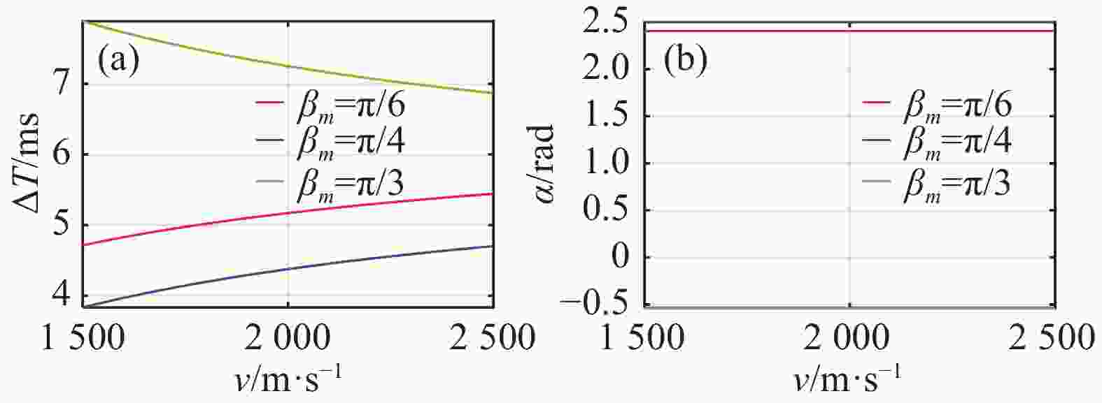
Figure 6. Relationship between the optimal initiation time, initiation azimuth and the fragment speed. (a)Optimal initiation time vs fragment speed; (b)Optimal initiation azimuth vs fragment speed
由图6可知在既定破片作用范围内,弹丸俯仰角
${\beta _m}$ 为$\pi /6$ 、$\pi /4$ 时,破片飞散速度越大,最佳起爆时间越长,${\beta _m}$ 为$\pi /3$ 时,破片飞散速度越大,最佳起爆时间越短;弹丸俯仰角确定时,最佳起爆方位角为定值,不随破片飞散速度发生变化;同一破片飞散速度情况下,${\beta _m}$ 为$\pi /3$ 时,最佳起爆方位角最小,${\beta _m}$ 为$\pi /4$ 时,最佳起爆方位角最大。 -
假设已知
${\psi _{{m}}} = - \dfrac{\pi }{4}$ ,$\left| {{{v}}} \right|$ =2 000 m/s,${{{r}}}_{mt{\rm{2}}}^{}$ =$[{\rm{3}} \quad{\rm{5}}\quad{\rm{6}}]^{\rm{T}}$ m,R=10 m,L=2.5 m,${{{{v}}}_{{t}}}$ =700$\left[ { - \frac{{\sqrt 3 }}{6}}\quad{ - \frac{{\sqrt 3 }}{2}}\quad{ - \frac{1}{3}}\right]^{\bf{T}}$ m/s,代入公式(25),可得最佳起爆时间和方位角与弹丸速度$\left| {{{{{v}}}_{\rm{m}}}} \right|$ 的变化关系如图7所示。
Figure 7. Relationship between the optimal initiation time, initiation azimuth and the projectile speed. (a)Optimal initiation time vs projectile speed; (b)Optimal initiation azimuth vs projectile speed
由图7可知在既定破片作用范围内,
$ {\beta _m}$ 为$ \pi /6$ 、$ \pi /4$ 、$ \pi /3$ 时,弹丸速度越大,最佳起爆时间越短,最佳起爆方位角越小;弹丸自身俯仰角越大,最佳起爆方位角变化越缓慢。相同目标特征长度情况下,$ {\beta _m}$ 分别为$ \pi /6$ 、$ \pi /4$ 、$ \pi /3$ 时,弹丸俯仰角越大,最佳起爆时间越短,最佳起爆方位角越大。 -
假设已知
${\psi _{{m}}} = - \dfrac{\pi }{4}$ ,$\left| {{{v}}} \right|$ =2000 m/s,$\left| {{{{{v}}}_{{m}}}} \right|$ =500 m/s,${{{r}}}_{mt{{2}}}^{}$ =$\left| {{{{{r}}}_{{{mt2}}}}} \right|$ $\left[ {\dfrac{3}{{\sqrt {70} }}}\quad{\dfrac{5}{{\sqrt {70} }}}\quad{\dfrac{6}{{\sqrt {70} }}} \right]^{\bf{T}}$ m,R=10 m,${{{{v}}}_{{t}}}$ =700$\left[ { - \dfrac{{\sqrt 3 }}{6}}\quad{ - \dfrac{{\sqrt 3 }}{2}}\quad{ - \dfrac{1}{3}}\right]^{\bf{T}}$ m/s,代入公式(25),可得最佳起爆时间和方位角与弹目距离$\left| {{{{{r}}}_{{{mt2}}}}} \right|$ 的变化关系如图8所示。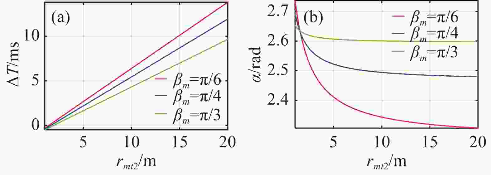
Figure 8. Relationship between the optimal initiation time, initiation azimuth and the distance between the projectile with the target.(a)Optimal initiation time vs the distance between the projectile and target;(b)Optimal initiation azimuth vs the distance between projectile and target
由图8可知在既定破片作用范围内,弹丸俯仰角
${\beta _m}$ 为$\pi /6$ 、$\pi /4$ 、$\pi /3$ 时,令最佳起爆时间为0时弹目距离为临界弹目距离,弹目距离小于临界弹目距离时,最佳起爆时间为负值,表示探测结束时已错过最佳起爆时机,此时应立即起爆战斗部;弹目距离大于临界弹目距离时,最佳起爆时间越短,最佳起爆方位角越大,最佳起爆时间随弹目距离变化呈线性关系;弹丸自身俯仰角越大,最佳起爆方位角变化越缓慢。相同目标特征长度情况下,${\beta _m}$ 分别为$\pi /6$ 、$\pi /4$ 、$\pi /3$ 时,弹丸俯仰角越大,最佳起爆时间越短,最佳起爆方位角越大。 -
假设已知
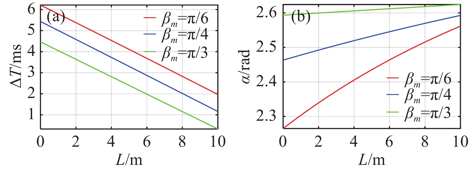
${\psi _{{m}}} = - \dfrac{\pi }{4}$ ,$\left| {{{v}}} \right|$ =2 000 m/s,$\left| {{{{{v}}}_{{m}}}} \right|$ =500 m/s,${{{r}}}_{mt{\rm{2}}}^{}$ =$[3\;\; 5\;\; 6 ]^{\rm{T}}$ m,R=10 m,${{{{v}}}_{{t}}}$ =700$\left[{ - \dfrac{{\sqrt 3 }}{6}}\;\;{ - \dfrac{{\sqrt 3 }}{2}}\;\;{ - \dfrac{1}{3}} \right]^{\bf{T}}$ m/s,代入公式(25),可得最佳起爆时间和方位角与目标特征长度L的变化关系如图9所示。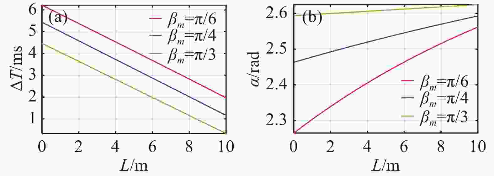
Figure 9. Relationship between the optimal initiation time, initiation azimuth and the target characteristic length.(a)Optimal initiation time vs the target characteristic length;(b)Optimal initiation azimuth vs the target characteristic length
由图9可知在既定破片作用范围内,弹丸俯仰角
${\beta _m}$ 为$\pi /6$ 、$\pi /4$ 、$\pi /3$ 时,目标特征长度越大,最佳起爆时间越短,最佳起爆方位角越大,最佳起爆时间随目标特征长度呈线性关系;弹丸自身俯仰角越大,最佳起爆方位角变化越缓慢。相同目标特征长度情况下,${\beta _m}$ 分别为$\pi /6$ 、$\pi /4$ 、$\pi /3$ 时,弹丸俯仰角越大,最佳起爆时间越短,最佳起爆方位角越大。 -
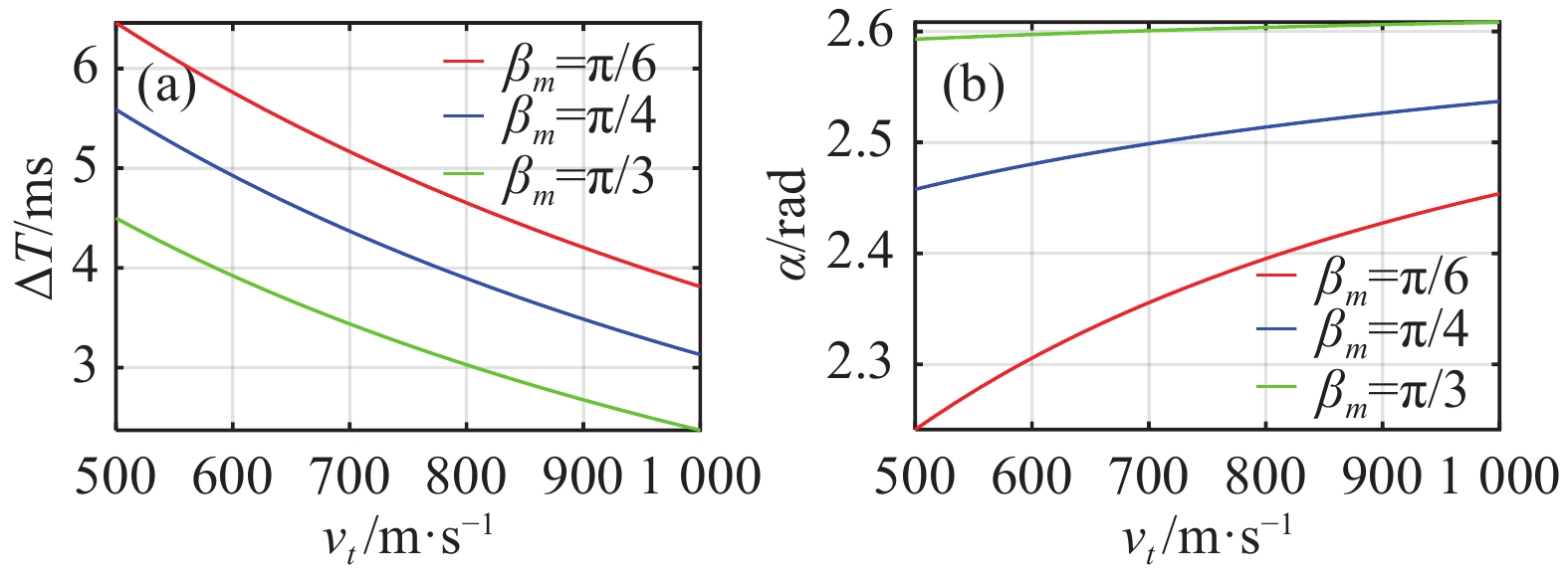
若已知
${\psi _{{m}}} = - \dfrac{\pi }{4}$ ,$\left| {{{v}}} \right|$ =2 000 m/s,$\left| {{{{{v}}}_{{m}}}} \right|$ =500 m/s,${{{r}}}_{mt{\rm{2}}}^{}$ =$\left[3\;5\;6\right]^{\rm{T}}$ m,R=10 m,L=2.5 m,${{{{v}}}_{{t}}}$ =$\left| {{{{{v}}}_{{t}}}} \right|$ $\left[{ - \dfrac{{\sqrt 3 }}{6}}\;{ - \dfrac{{\sqrt 3 }}{2}}\;{ - \dfrac{1}{3}}\right]^{\bf{T}}$ m/s。代入公式(25)可得最佳起爆时间和方位角与目标速度的变化关系如图10所示。
Figure 10. Relationship between the optimal initiation time, initiation azimuth and the target speed. (a)Optimal initiation time vs target speed; (b)Optimal initiation azimuth vs target speed
由图10可知在既定破片作用范围内,弹丸俯仰角
${\beta _m}$ 为$\pi /6$ 、$\pi /4$ 、$\pi /3$ 时,目标速度越大,最佳起爆时间越短,最佳起爆方位角越大;弹丸自身俯仰角越大,最佳起爆方位角变化越缓慢。目标速度相同情况下,${\beta _{\rm{m}}}$ 为$\pi /6$ 、$\pi /4$ 、$\pi /3$ 时,弹丸俯仰角越大,最佳起爆时间越短,最佳起爆方位角越大。 -
文中阐述了同步扫描周视脉冲激光引信的工作原理,分析了目标探测过程中可探测的多个目标位置点,计算了各探测点在弹体坐标系中的位置坐标。根据各探测点的距离和方位信息,建立了基于多探测点的目标速度模型,通过目标速度模型对目标速度进行解算,与攻击目标正常速度范围进行比对,来辨别目标真伪。在目标速度模型的基础上,以破片攻击目标特征几何中心为目的,求解出引信最佳起爆时间和方位角,并分析了最佳起爆模型的影响因素及其对最佳起爆时间和方位角的影响。
Modeling and simulation of multi-detection point optimal initiation of synchronous scanning panoramic pulse laser fuze
doi: 10.3788.IRLA202049.0403001
- Received Date: 2020-02-10
- Rev Recd Date: 2020-03-26
- Publish Date: 2020-04-24
-
Key words:
- panoramic laser fuze /
- target detection /
- aimed warhead /
- optimal initiation model
Abstract:
Panoramic laser fuze usually calculates the optimal initiation time and initiation azimuth only based on single measured target direction and distance, the calculation accuracy is low. On the other hand, fuze can not distinguish the authenticity of targets, it is easy to cause "false alarm" or accidental bombing. Based on the working principle of the synchronous scanning panoramic pulse laser fuze, the direction, distances and position coordinates of multiple detection points were analyzed. The target velocity model based on multiple detection points were established, which can calculate the target speed and judge whether the target was true. The geometric center position of the target feature was solved, and the optimal initiation time and azimuth calculation model were established to obtain the maximum damage effectiveness of the warhead. The influence factors of the optimal initiation time and azimuth were analyzed. The research can provide a reference for the target identification and directional initiation of the panoramic laser fuze.


 DownLoad: