


-
激光跟踪仪因其高精度以及便携等优势,在大尺寸坐标测量中有着十分广泛的应用[1]。但相较测距精度,其测角误差较大[2~3],且由于角度误差的放大作用,所测目标距跟踪仪越远,角度误差带来的影响越明显。多边法坐标测量系统是一种利用多台激光跟踪仪组成测量网,只利用激光跟踪仪测得的距离数据对三维坐标进行解算的一种方法,能够避免激光跟踪仪角度测量带来的误差,提高激光跟踪仪三维坐标测量的精度。日本的Toshiyuki Takatsuji,Mitsuo Goto等利用激光干涉测距设备进行了早期的多边法测量网研究[4-5];天津大学的张国雄团队针对激光跟踪干涉仪进行了跟踪结构、自标定方法以及布局方式等方面研究[6-8];合肥工业大学胡进忠基于绝对测距式激光跟踪仪建立了多边法模型,并研究了无目标点自标定方法以及系统的最佳布局[9-10]。此外,信息工程大学的范百兴、王罗刚等对激光干涉测距三维网加权秩亏自由网平差进行了研究[11-12]。
以上研究中除无目标点自标定模型外均至少需要四站进行多边法组网,而无目标点自标定模型最少需要三站即可进行多边法组网,但其要求跟踪仪之间能够互相测得测量原点之间的距离,实现困难,因而早先的研究只进行了仿真来推断方案的可行性[13]。文中基于无目标点自标定模型进行了进一步的研究,设计了一种夹具,通过夹具能够将靶球固定在跟踪仪测头上,通过跟踪仪跟踪机构两轴良好的正交性,使得跟踪仪测头转动时,靶球始终位于以测量原点为球心的球上,通过对球心坐标进行拟合间接实现对测量原点坐标进行测量的目的,同时分析了系统的误差并进行了实验验证系统的性能。
-
多边法三维坐标测量系统常由测量基站、待测目标和数据处理环节组成。
多边法是通过多个测量基站对同一待测目标进行测量获得基站与待测点间的距离,使用距离公式组成方程组,求解方程组达到对三维坐标进行解算的目的。测站之间的相对位置需要已知,即完成自标定,才能利用方程组计算空间坐标,因而需要找到方便、高精度的自标定方法。
-
自标定的目的是要得到测站间的位置关系,具体来说是测站的测量原点之间的位置关系,若能直接测得各测站测量原点之间的距离,就可以不通过测量目标点也达到自标定的目的。
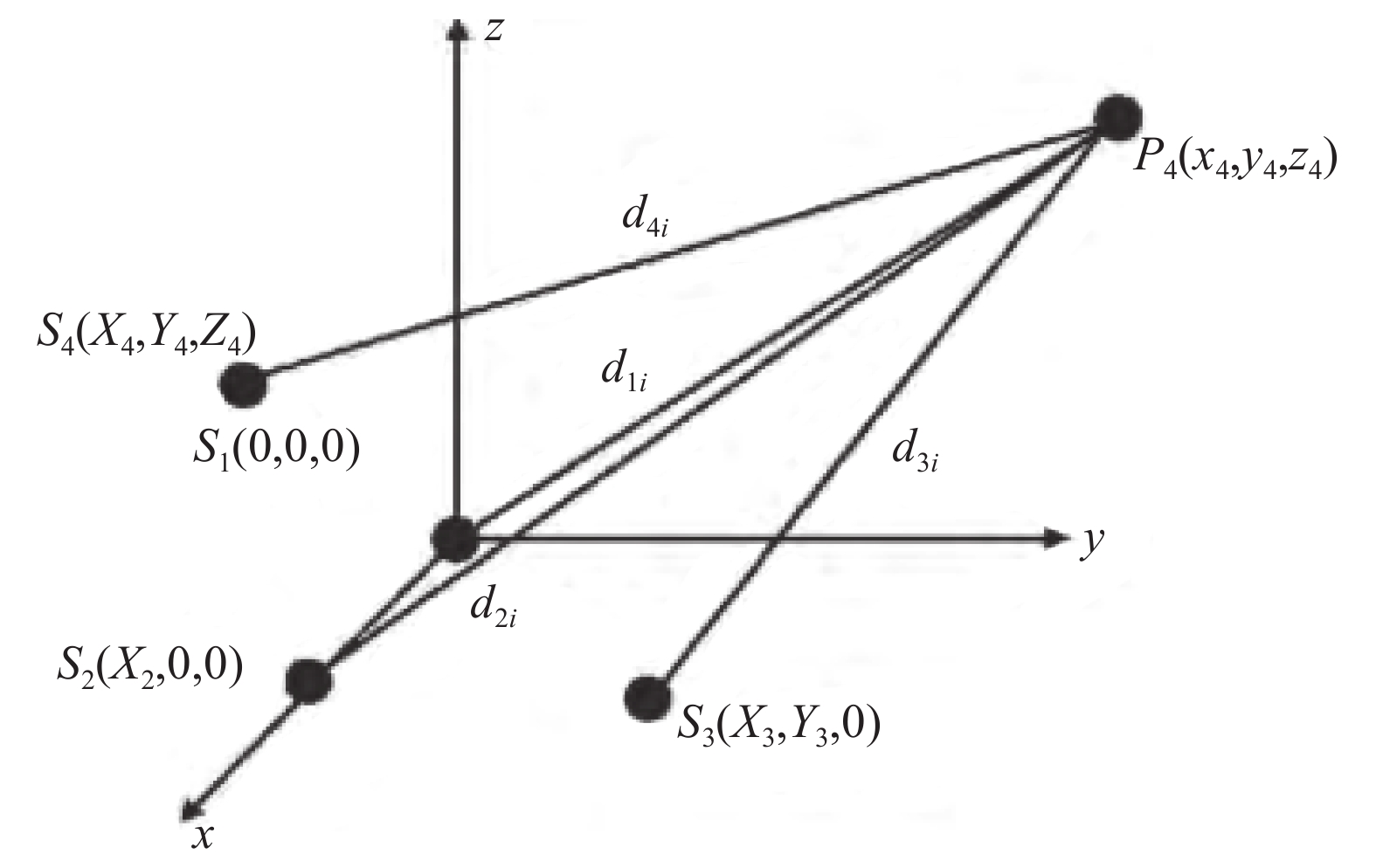
如图1所示,自标定时按照第一测站在原点,第二测站在
$x$ 轴上,第三测站在$xoy$ 平面内,其余测站在空间随意分布的方式建系。
Figure 1. Self-calibrated layout of four-station
由于多边法测量三维坐标至少需要三站,而多边系统通常使用四站组建,因而在无目标点自标定方案下,可以构建四站模型与三站模型,四站模型在合肥工业大学的相关研究中已经提及[13],文中将列出三站模型的推导。
三站自标定解算按如下方程组进行:
第i站的坐标为
$\left( {{x_i},{y_i},{z_i}} \right)$ ,i=1,2,3。该方程可以直接求解得到公式(2):
正负值根据实际测量环境确定,得到自标定结果即三测站的坐标分别
$(0,0,0),({x_2},0,0),({x_3},{y_3},0)$ 。 -
激光跟踪仪是一种建立在球坐标基础上的测量仪器,通常都具有偏摆和俯仰两个自由度的转轴,两个转轴间具有良好的正交性,其交点即为跟踪仪的测量原点,测量原点通常位于测头内部,难以直接测量得到其坐标。因而文中设计了一种如图2所示的夹具,夹具下方的螺纹孔用来将夹具安装在测头上后进行固定,上方螺纹孔可连接带有螺纹的靶座,用于吸附靶球。这样就可以通过夹具将靶球刚性固连在跟踪仪测头上。因跟踪仪两转轴良好的正交性,无论测头如何转动,夹具末端的靶球始终都在一个以跟踪仪测量原点为球心的球上运动。
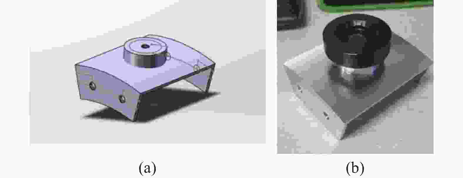
Figure 2. Design drawing and physical drawing of the fixture
通过另一台跟踪仪对被挂载的靶球坐标进行测量,并将测量点坐标按照最小二乘原理得到待求的测量原点坐标,进而得到两测站测量原点间的距离。
-
传统激光跟踪仪多边法至少需要四台激光跟踪仪进行测量,而激光跟踪仪价格高昂,所以在构建多边测量系统时常采用移站的方式,即采用一台激光跟踪仪,在不同的位置分别对所有目标点进行测量。这种方式虽然能降低成本,但每一次移站就要将全部测量点测量一遍,成倍增加工作量的同时引入每个目标点测量时的重复性误差,对测量结果精度造成影响。而对于无目标点自标定模型,由于不存在目标点,省去了大量的目标点测量工作;由于需要使用一台激光跟踪仪对另一台激光跟踪仪的位置进行测量,所以需要两台跟踪仪。
综合测站位置互测和移站的需求,现采用一种两台四站的球心拟合无目标点自标定方法,其中一台激光跟踪仪位置固定作为“原点跟踪仪”,另一台激光跟踪仪作为“移站跟踪仪”,按照如下步骤进行测量:
(1)将一台跟踪仪固定在某一位置,并以该跟踪仪测量中心为坐标原点,将这台激光跟踪仪称为“原点跟踪仪”,并使用“原点跟踪仪”对待测目标点进行测量。
(2)在另一台跟踪仪测头上连接夹具、挂载靶球,将此跟踪仪称为“移站跟踪仪”,并将其放置在位置1,使用“原点跟踪仪”对位置1的“移站跟踪仪”进行球心拟合测量,得到“原点跟踪仪”与“移站跟踪仪”测量原点间的距离。
(3)拆下夹具,使用“移站跟踪仪”在现位置对待测目标点进行测量。
(4)移动“移站跟踪仪”至位置2,重新连接夹具并重复步骤(2)、(3)。
(5)移动“移站跟踪仪”至位置3,重新连接夹具并重复步骤(2)、(3)。
(6)按无目标自标定方法进行自标定解算,并按前方交会解算待测点坐标。
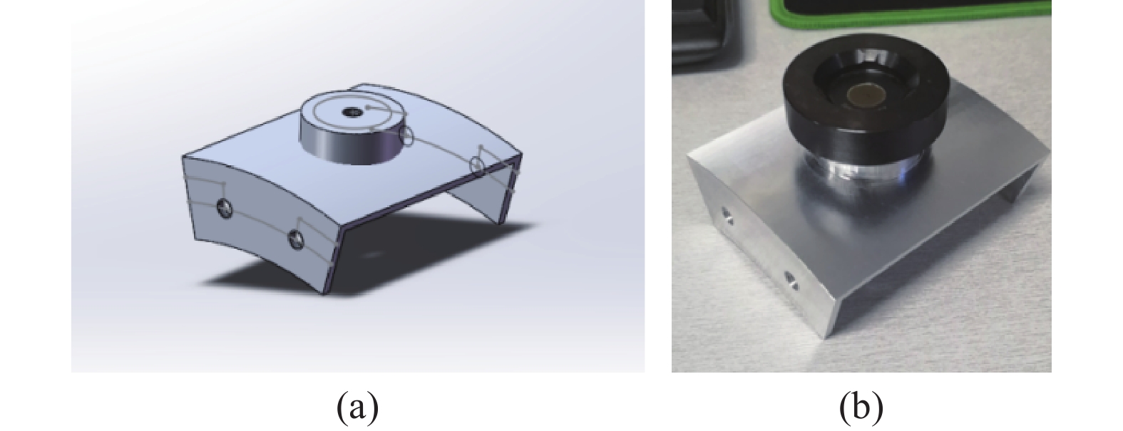
系统构建如图3所示。

Figure 3. Construction of spherical center fitting self-calibration system for four-station model using two laser trackers
构建由三站构成的多边系统时,只需在上述环节上去除掉最后的位置3即可。三站模型与四站模型的区别在于,在自标定后,使用激光跟踪仪测长结果对待测点坐标进行解算时,三站模型建立的方程组为恰定方程组,四站模型建立的方程组为超定方程组。
-
由于该方案在跟踪仪测头上挂载了器件,包括夹具、靶座以及靶球,这会造成跟踪仪测量原点位置的偏差,但由于需要挂载器件的只有“移站跟踪仪”,即在每个测站位置,挂载器件的是同一台跟踪仪,保证挂载位置基本不变的前提下,可认为各测站受挂载影响而造成的测量原点位置偏移大小相同。
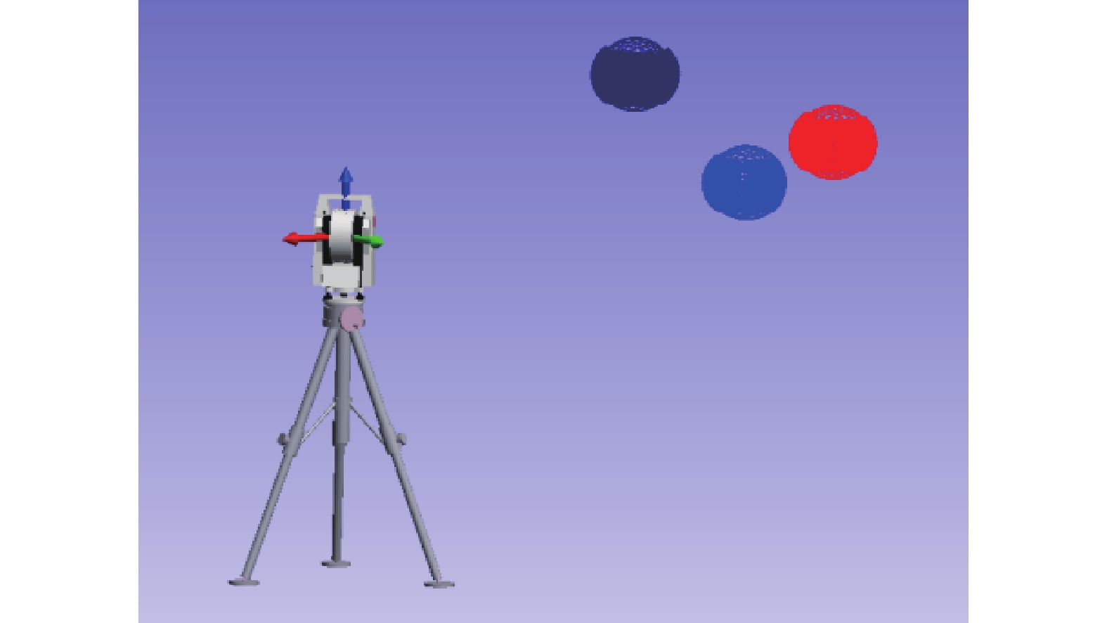
对于激光跟踪仪这类二维转轴结构,挂载带来的位置偏移如图4所示,在重力作用下,主要的偏移方向应为Z轴方向,X轴和Y轴方向的偏移误差相对Z轴方向较小且会在球心拟合的测量过程中以对称的方式得到一定的消除。由于对球心的拟合是尽量均匀覆盖以测头中心为球心、靶球中心到测头中心距离为半径的球面,X轴和Y轴的偏差会由于对称性而消去。

Figure 4. Position error of original point
为探究测量原点位置偏移对测量结果的影响,可在自标定结果中对移站跟踪仪坐标添加适当大小的“误差”,观察标准尺长度的测量结果变化,若测量结果变化不明显,证明测量原点位置偏移带来的误差对测量结果影响不大,文中提出的球心拟合方案可以接受。
除去测量原点偏移对测量中心自标定造成的影响以外,激光跟踪仪单点坐标测量误差以及测量过程中的重复性误差的存在也会对球心拟合结果造成影响。
在测量过程中,为准确拟合球心坐标,对球面上多个位置都进行了测量,尽可能地覆盖了整个球面,测量点数达到上千个,这样一来,测量点的重复性误差可以视为已消去。
“移站跟踪仪”与原点跟踪仪之间的距离大概在3 m以内,由于距离较短,点位测量精度较高,对球心拟合造成的误差影响也较小。
-
为验证文中方法的可行性与有效性,利用该方法进行了自标定实验和测量精度验证实验,并对误差进行了分析。
-
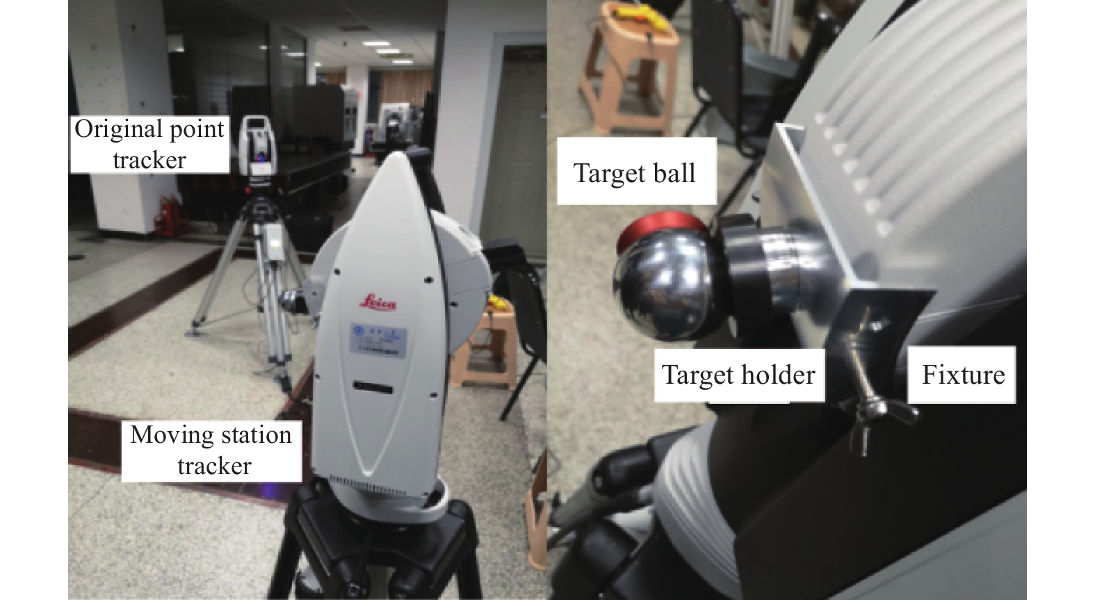
根据前文介绍的系统构建方式,采用LEICA AT403激光跟踪仪作为“原点跟踪仪”,采用LEICA AT960激光跟踪仪作为“移站跟踪仪”,两种型号的跟踪仪具有相同的标称测距精度和点位测量精度,将夹具固定在LEICA AT960的测头上连接靶座与靶球,如图5所示。

Figure 5. Schematic of self-calibration and fixture connection
由“原点跟踪仪”分别对三个位置的“移站跟踪仪”上挂载的靶球坐标进行连续测量,得到三组点云,对该三组点云分别进行球心拟合,拟合时将公差设置为0.02 mm,拟合情况如图5所示,拟合结果如表1所示。
Position Position 1 Position 2 Position 3 Number of points 1 000 1 000 1 000 Common difference/mm 0.020 0.020 0.020 Number of effective point 646 617 469 Spherical center coordinate/mm X Y Z X Y Z X Y Z –2 212.401 –952.396 –29.726 –3 132.017 –1 866.354 –33.046 –4 084.727 –4 692.426 –151.759 Radius/mm 134.669 134.662 134.526 Table 1. Spherical center fitting data and result
由拟合得到的球心坐标计算得到两台四站跟踪仪间的距离分别为
${d_{21}} = {\rm{2\;408}}{\rm{.871\;mm}}$ ,${d_{{\rm{3}}1}} = {\rm{3\;646}}{\rm{.080\;mm}}$ ,${d_{{\rm{4}}1}} = {\rm{6\;223}}{\rm{.093\;mm}}$ ,${d_{{\rm{32}}}} = {\rm{1\;296}}{\rm{.543\;mm}}$ ,${d_{{\rm{42}}}} = {\rm{4\;184}}{\rm{.295\;mm}}$ ,${d_{{\rm{43}}}} = {\rm{2\;984}}{\rm{.700\;mm}}$ ,将该组数值代入到四站无目标点自标定模型完成自标定,结果为${x_2} = {\rm{2\;408}}{\rm{.871}}$ ,${x_{\rm{3}}} = {\rm{3\;614}}{\rm{.875}}$ ,${x_{\rm{4}}} = {\rm{5\;608}}{\rm{.691}}$ ,${y_{\rm{3}}} = {\rm{476}}{\rm{.022}}$ ,${y_{\rm{4}}} = {\rm{2\;692}}{\rm{.132}}$ ,${z_{\rm{4}}} = - {\rm{147}}{\rm{.995}}$ 。 -
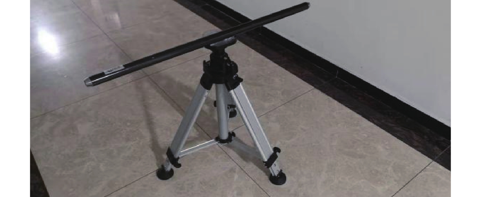
在得到测站间相对位置即完成自标定后,通过对空间中一定长度的标准尺两端距离进行测量来验证系统的测量精度。实验中使用标称长度1 000.943 mm的标准尺,如图6所示。将标准尺放置在距“原点跟踪仪”约20 m的位置上,使用“原点跟踪仪”对标准尺两端点进行测量,使用“移站跟踪仪”在位置1、位置2、位置3分别对标准尺两端点进行测量,得到标准尺两端点的三维坐标。被测标准尺如图7所示。

Figure 6. Spherical center fitting

Figure 7. Scale bar to be measured
按照多边法原理解算得到端点坐标,再根据距离公式得到标准尺的长度。另外通过保存的激光跟踪仪笛卡尔坐标,可以得到三站跟踪仪每一站测得的包含角度误差影响的标准尺长度。两者的数据及比较如表2所示。
Point 1 Point 2 Length /mm Absolute value of
difference/μmX/mm Y/mm Z/mm X/mm Y/mm Z/mm Original point tracker –15 546.039 –15 248.192 –649.910 –14 824.764 –15 942.233 –659.255 1 001.008 65 Moving station tracker 1 17 834.335 –7 998.228 –672.218 18 258.769 –7 091.881 –664.588 1 000.833 110 Moving station tracker 2 –1 628.084 –18 162.704 –1 013.202 –633.001 –18 269.683 –1 029.440 1 000.949 6 Moving station tracker 3 –9 217.2173 –12 558.486 –580.287 –8 375.950 –13 100.796 –594.329 1 001.013 70 Multilateral 20 315.755 7 843.199 –586.987 19 928.030 8 764.959 –630.0941 1 000.915 28 Table 2. Comparison of scale bar length measured by four-station multilateral method and single station
两种型号的激光跟踪仪标称点位误差均为±(15 μm+6 μm)/m,则在20 m的距离上,标称点位误差约为135 μm。标准尺标称长度为1000.943 mm,由数据处理得到的四站单台激光跟踪仪对标准尺长度的测量误差绝对值分别为65 μm,110 μm,6 μm,70 μm,平均值为62.75 μm,而由多边法计算得到的标准尺长度误差绝对值为28 μm。
-
除四站模型外,也可以构建三站模型,在文中所述系统构建方案的基础上减掉一站,得到三站系统,用相似的方式对三站系统的性能进行验证,由于可预见的三站系统相对于四站系统的性能下降,验证三站系统时在约7.5 m的距离上放置标称长度为969.045 mm的标准尺,得到结果如表3所示。
Point 1 Point 2 Length/mm Absolute value of
difference/μmX/mm Y/mm Z/mm X/mm Y/mm Z/mm Original point tracker 4 869.88 5 909.79 –451.91 5 284.89 5 034.15 –439.30 969.164 119 Moving station tracker 1 4 869.82 5 909.84 –452.02 5 284.76 5 034.17 –439.39 969.095 50 Moving station tracker 2 4 869.77 5 909.93 –452.01 5 284.81 5 034.32 –439.41 969.076 31 Multilateral 5 507.68 –5 324.49 –400.97 4 601.88 –5 668.67 –393.14 969.024 21 Table 3. Comparison of scale bar length measured by three-station multilateral method and single station
在7.5 m距离上的跟踪仪标称点位误差为60 μm,三单站对标称969.045 mm标准尺长度进行测量时的长度误差为119 μm,50 μm,31 μm,平均值为67 μm,而由三站系统按多边法结算得到的标准尺误差为21 μm。
-
如前文设想,通过人工在自标定结果坐标的X,Y,Z三个方向上添加“误差”并观察结果的改变,若结果变化有限,则可证明该方案的主要误差对测量结果影响较小。
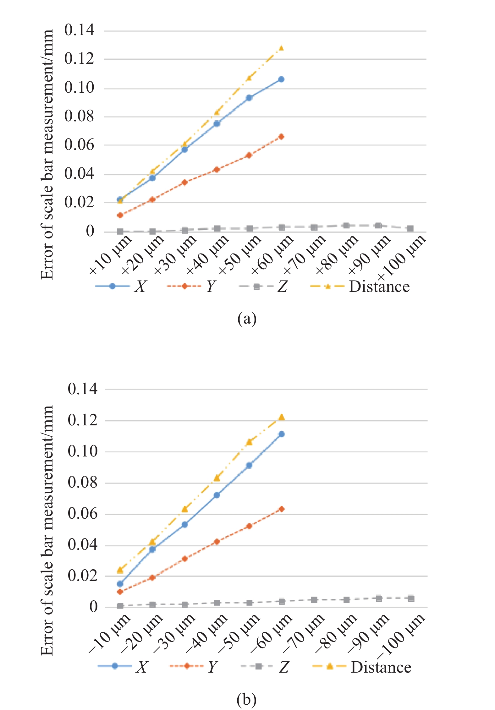
现对四站模型的自标定结果添加误差,在X,Y方向上分别添加±10 ~ ±60 μm的误差,在Z方向上添加±10 ~ ±100 μm的误差,为观察各方向误差影响的严重程度,同时在测站的距离测量结果上添加误差,得到同等大小的测距误差造成的测量结果变化。得到的测量结果与不添加误差时的测量结果的差的绝对值如图8所示,其中图8(a)为添加正向误差时的结果,图8(b)为添加负向误差时的结果。

Figure 8. Influence of original point error on measurement result
可知X,Y方向上误差引起的结果改变相对较为明显,但也与相同大小的测距误差引起的结果改变相当。而如上文分析,文中方案中主要误差方向Z方向上的误差引起的结果改变很小,在添加+100 μm误差时,测量结果改变最大只有3 μm,添加–100 μm误差时,测量结果改变只有6 μm,可认为Z方向上的误差对测量结果几乎无影响。进而得到结论,在测头上挂载重量引入的误差,Z方向对测量结果几乎不产生影响,而X,Y方向的误差自身很小,即使产生影响也与跟踪仪本身的测距误差的影响量级相当,可证明文中方案可行。
-
文中出于提高激光跟踪仪三维坐标测量精度的目的,提出了一种基于无目标点自标定模型的采用球心拟合的多边法系统构建方案。与传统方案相比,文中方案无需在空间中布置目标点,而是通过设计一种轻质的夹具,将靶座与靶球固定在跟踪仪测头上,实现了对跟踪仪测量原点坐标的间接测量,再由无目标点自标定模型即可完成多边系统的自标定。
根据所设计的方案进行了自标定实验以及多边法的精度验证实验,通过对标准尺两端点标准长度的测量实验验证了方案的精度。精度验证试验的结果表明:球拟合多边法方案,四站模型将20 m距离上对标称长度1 000.943 mm标准尺长度的测量误差由单台跟踪仪的最大110 μm减小至28 μm,三站模型将7.5 m距离上对标称长度969.045 mm标准尺长度的测量误差由单台激光跟踪仪的最大119 μm减小至21 μm。另外对文中方案的误差进行了分析,通过数据分析证明了方案引入的误差对测量结果几乎没有影响。文中方案提高精度的同时只使用了两台激光跟踪仪,降低了传统多边法使用四台以上跟踪仪的成本。
Multilateral laser tracking system self-calibration method based on spherical center fitting
doi: 10.3788/IRLA20190438
- Received Date: 2019-11-20
- Rev Recd Date: 2019-12-19
- Available Online: 2020-09-22
- Publish Date: 2020-08-28
-
Key words:
- multilateral /
- laser tracker /
- spherical center fitting-self-calibration /
- coordinate measurement
Abstract: With the increase of precision requirements for manufacturing, processing and assembly of large scale workpieces and equipment, high precision measurement system is needed to measure the machining and assembling process of workpiece. Multilateral laser tracking 3D coordinate measuring system measures the distance data to solve the space point coordinates which can avoid the error caused by the angle measurement of laser tracker. Based on non-target self-calibration model, a spherical center fitting-self-calibration method for multilateral laser tracking 3D coordinate measuring system was constructed in this paper. By mounting an fixture to the laser tracker and moving station, a four station laser tracking 3D coordinate measuring system can be constructed. In addition, a three station system was also constructed. The experimental results show that the error of distance between the two ends of the scale bar with nominal length 1000.943 mm measured by three-station system is reduced from 110 μm to 28 μm at the distance of 20 m, and the distance error between the two ends of the scale bar with nominal length of 969.045 mm measured by four-station system is reduced from 67 μm to 21 μm at the distance of 7.5 m. Compared with single-tracker measurement, the precision is improved, the number of station and the cost for the system are reduced compared with traditional multilateral measurement system. The system can realize high precision for 3D coordinate measurement in industrial field.


 DownLoad: