


-
Currently, there are mainly three types of imaging devices to acquire the three dimensional (3D) information of the static and dynamic world around us, which are structured light cameras, time-of-flight cameras and multiple synchronous cameras [1-4]. However, these imaging devices all suffer from complicated configurations and high costs. The newly-developed portable plenoptic camera can also be used to record the 3D information of the objects [5-9]. Generally, a plenoptic camera can be constructed by inserting a microlens array (MLA) between the main lens system and the imaging sensor in a conventional camera. However, the rendered images restored from plenoptic cameras have a disappointingly low resolution because a large proportion of the sensor for direction resolving is already taken up. Boominathan
et al. showed a hybrid imaging system consisting of a plenoptic camera and a traditional digital single lens reflex camera to achieve high-resolution digital refocusing, but the hybrid system is not portable [10]. Generally, typical plenoptic cameras mentioned above utilize traditional MLA. In recent years, liquid-crystal microlens arrays (LCMLAs) have sprang up as a potential substitution for MLA [11-13]. So far, nematic LC materials have been widely used in LC lens applications. Nematic LC molecules are rod-like and their long molecule axis can be preferably oriented in a special direction. The nematic LC materials sealed in two electrodes will reorient their directors along the electric-field direction stimulated in LC layer. If the stimulated electric-field is nonuniform radially, a gradient index lens can be shaped due to the variance of the tilting angles of LC molecules.
In this paper, a dual-mode plenoptic camera (DMC) used for 3D reconstruction of static scene based on the LCMLA is proposed. When a voltage signal with needed RMS value is applied between the electrodes of the LC device, the DMC will present a plenoptic imaging mode for acquiring 3D radiation parameters of objects. If the voltage signal is turned off, the DMC will be a traditional camera so as to exhibit a dual-mode imaging feature. Through fusing the 3D plenoptic data and corresponding high-resolution planar data of the same objects, a high-resolution 3D reconstruction can be achieved effectively so as to highlight a way to remarkably increase the 3D imaging resolution based on the LCMLA-sensor chip with a dual-mode imaging ability.
-
The LCMLA is the key component of the DMC. In plenoptic mode, it acts as the microlens array which can focus the incident rays onto the sensor. Moreover, it must permit the transmittance of the rays in the planar mode. The appropriate materials are chosen and the structure is designed as shown in Fig.1(a). It includes two glass substrates with a thin indium tin oxide (ITO) layer on them as the electrodes. The thicknesses of the glass substrate and the ITO layer are ~500 μm and ~50 nm separately, and the square resistance of the ITO film is ~200 Ω. The ITO layer of the top substrate is etched with an array of circular holes with the diameter of 128 μm and the hole pitch of 160 μm via UV-photolithography and wet etching, whereas the bottom substrate is not etched. Both the top and the bottom substrates are coated with a polyimide (PI) layer by spin-coating. The PI layer of the electrodes are rubbed antiparallel to make the nematic LC molecules instilled align in the same direction in the natural state. The electrodes are sealed face to face with an adhesive mixed with a number of 20-μm-diameter microspheres along the edges to form an inner 20-μm-thick microcavity for LC materials. Figure1(b) shows an actual LCMLA developed by ourselves.
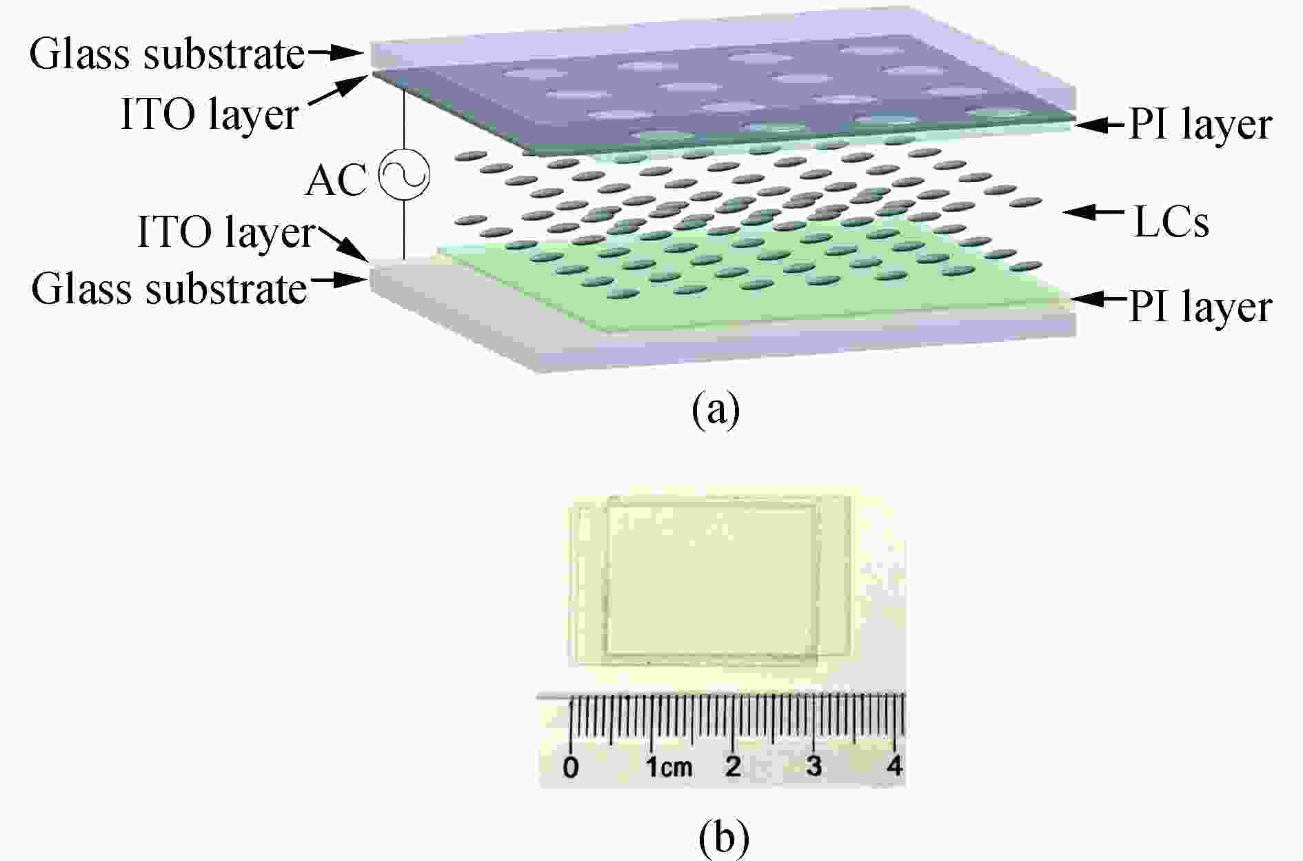
Figure 1. LCMLA device. (a) 3D structure (not in scale) and (b) an actual LCMLA with two conductive tapes
Generally, LC materials present obvious birefrigent. The angle between the optic axis and beam propagation direction determines the refractive index ne with respect to extraordinary rays, but does not affect the refractive index no of ordinary rays (usually ne > no). When a voltage signal is applied between two electrodes of the LCMLA constructed, a radially nonuniform electric-field will be generated in each microlens, which means that the electric-field intensity will be increased gradually from the center to the edge, and then the reorientation of LC molecules will also present a similar variance trend. If an appropriate signal voltage is applied, the refractive index for extraordinary rays will decrease from ne at the center to no nearing the edge in each microlens. Therefore, an array of gradient index microlenses is formed to converge incident extraordinary rays.
As shown in experiments, the variance of the electric-field stimulated in LC layer will result in a change of the focal length in a relatively small range. The LC material used by us is E44 from Merck, and their indexes are no=1.523 and ne=1.778. An experimental relation between the focal length and the applied RMS voltage is shown in Fig.2. A square-wave signal with a frequency of 1 kHz is employed to drive the LCMLA. Their focal length can be shifted in a range of ~1.55 mm to ~2.15 mm when the voltage signal is in the range from ~3.0 Vrms to ~15.0 Vrms. If the voltage signal is more than a value of ~15.0 Vrms, the electric-field intensity will be too strong to generate an effective spatial refractive index distribution. It should be noted that not all voltage signal between ~3.0 Vrms and ~15.0 Vrms can lead to an ideal imaging quality. According to our experiments, ~7.0 Vrms is a typical RMS value for generating a fairly sharp object image. Since the aim of performing electrically tuning focal length is only to acquire an ideal imaging quality, the voltage signal of ~7.0 Vrms is chosen as a common RMS value for driving our DMC in experiments. Thus the focal length of the LCMLA in our DMC is ~1.55 mm.
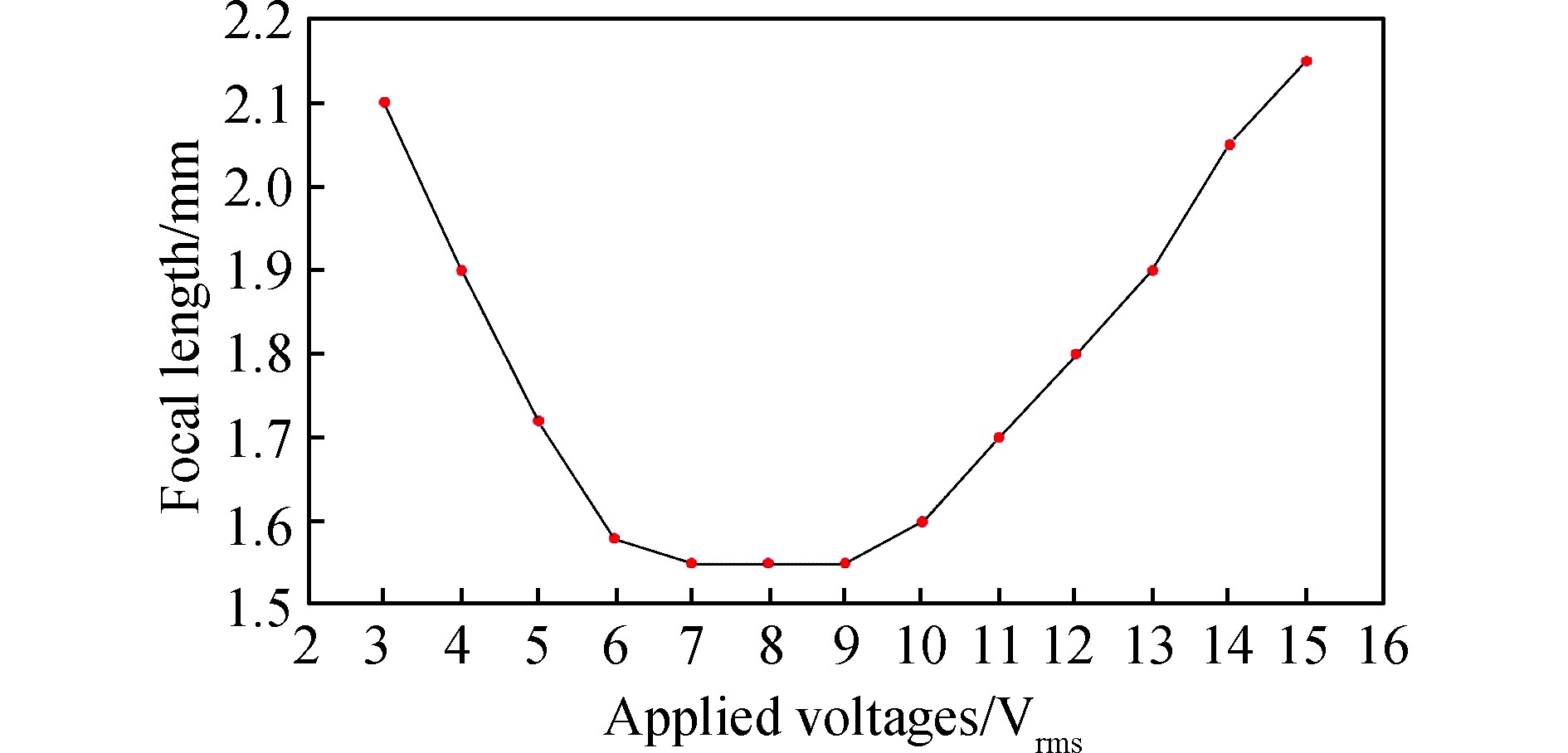
Figure 2. Focal length vs the signal voltage applied over the LCMLA fabricated by us
-
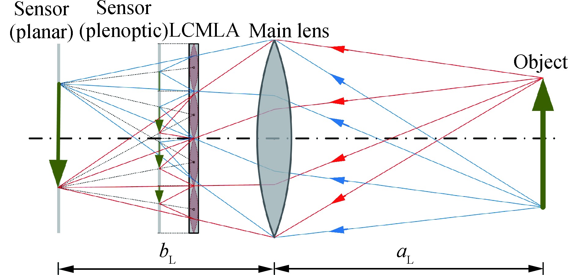
The schematic layout of the DMC is shown in Fig.3. It principally includes three components, the main lens system, the LCMLA, and the imaging sensor. Incident rays coming from objects are converged firstly by the main lens system. In the planar imaging mode, beams passing through the LCMLA will maintain their propagation directions but still experience a very small phase delay in the optical axis direction. A real image will be formed at the imaging plane through the main lens system. The sensor should be positioned at the imaging plane for capturing sharp images. Considering an ideal lens system, a relationship between the object distance aL and the image distance bL satisfies a common thin lens equation as the following.
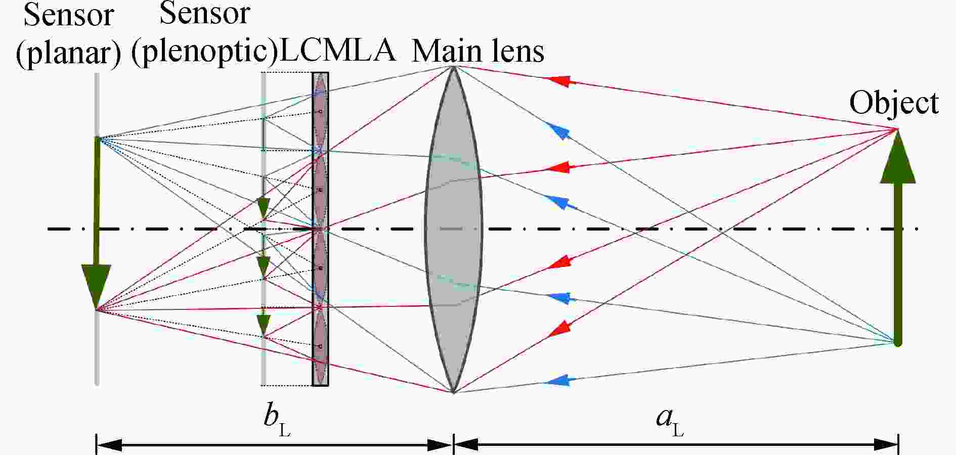
Figure 3. Layout of the DMC (not in scale)
where fL represents the focal length of the main lens system.
In the plenoptic imaging mode, incident rays passing through the LCMLA will be bent and then focused onto the plenoptic imaging plane before reaching the real imaging plane of the main lens system. In this occasion, the sensor should be moved towards the main lens system to acquire raw imaging data of the object. It is obvious that the rays from the same object point are split by several adjacent LC microlenses and then generate several image points on the sensor. A pinhole model is used to determine the exact positions of these points. Thus, each microlens can image the whole or part of the real object. The micro image generated by each microlens is called an elemental image. It is evident that the elemental images are overlapped and then the overlapping extent is determined by the triangulation of the DMC and the distance of the object point from the DMC. It is obvious that one object point is projected as one image point in the planar imaging mode, whereas multiple image points in the plenoptic imaging mode. Thus, the resolution of the rendered image restored from raw imaging data obtained in the plenoptic imaging mode is reduced sharply than that captured in the planar imaging mode.
It should be noted that the LCMLA and the sensor in our model is all set before the real image plane of the main lens system, and then the LCMLA will project a virtual object into a real image. However, they can also be put at an appropriate position behind the real image plane of the main lens system, which means that a real image can be formed before the relay imaging. Its theoretical model is almost the same as our model, and only our model is discussed carefully in the following.
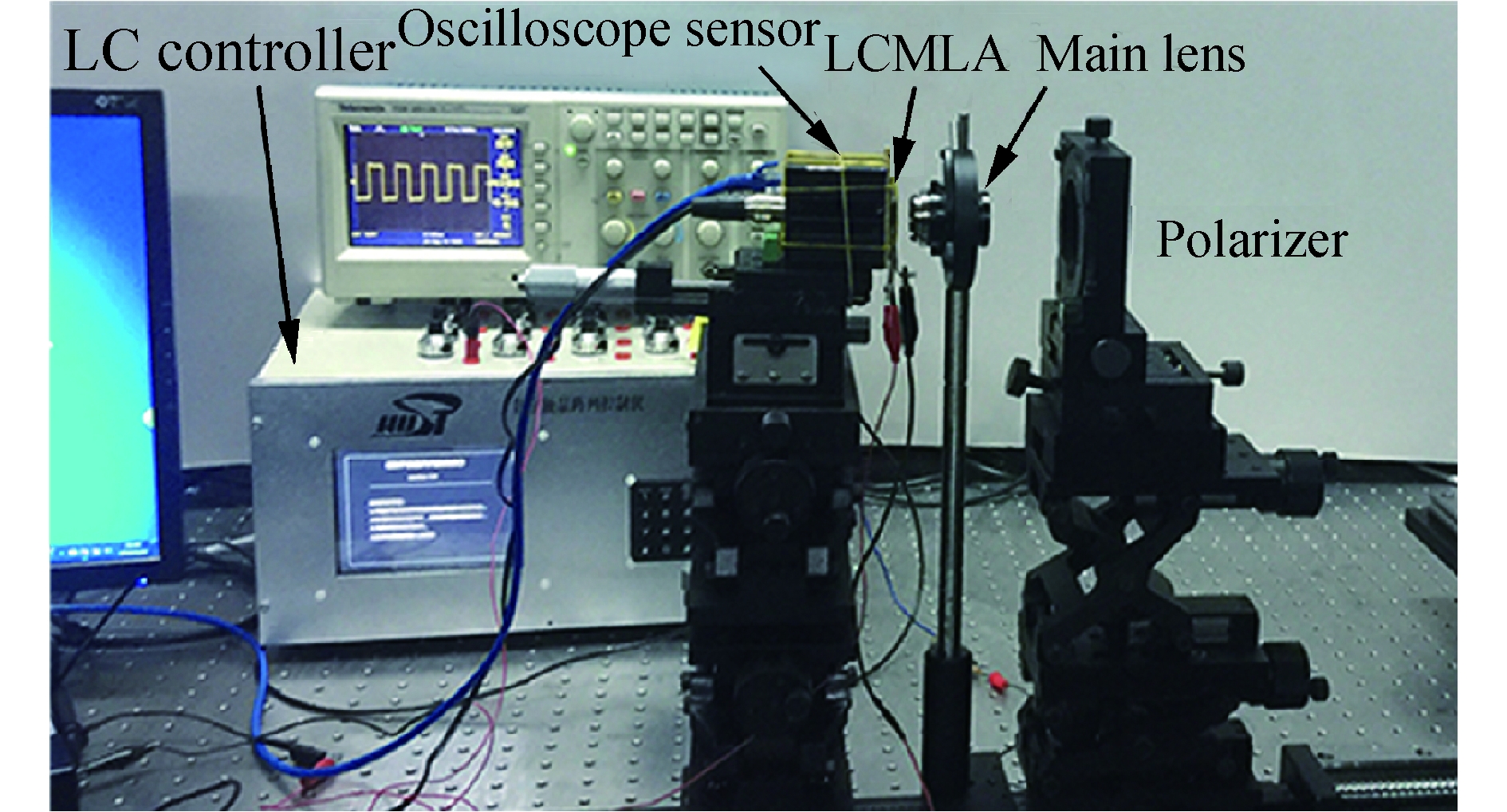
Figure 4 shows the DMC prototype constructed for 3D high-resolution reconstruction. The size of the sensor is 4 384×3 288 with a pixel pitch of 1.4 μm, which is connected with a computer to save the raw image data acquired. The LCMLA is powered by a LC Controller developed by ourselves, which provides a stable square-wave voltage signal with an RMS value ranging from 0 to 30.0 Vrms and a frequency of 1 kHz. An oscilloscope is adopted to monitor the applied voltage signal. The LCMLA is coupled tightly onto the surface of the protecting window of the sensor, and the distance between the LCMLA and the photosensitive surface of the sensor is ~1.3 mm. The LCMLA-sensor are fixed onto a three-dimensional stage. The main lens system with a focal length of 35 mm is just located before the LCMLA-sensor so as to construct a DMC prototype. To filter the ordinary rays of incident beams, which will bring relatively strong noise into plenoptic imaging signals, a polarizer is inserted in the measured light-path.
-
In the plenoptic imaging mode, the aperture of the main lens system is a determinant factor for the size selection of elemental images. Figure 5 shows several typical cases when the size of elemental images is changed with the aperture of the main lens system. As shown in Fig.5(a), the sensor coupled with the microlenses are not fully utilized because the aperture is too small. To utilize the sensor to the maximum, adjacent elemental images should be tangent without any overlapping, as shown in Fig.5(b). If the aperture of the main lens system is too large, adjacent elemental images will overlap as shown by Fig.5(c).

Figure 5. Elemental images acquired when the aperture is, (a) small, (b) suitable, and (c) large
As shown in Fig.6, the rays propagating towards the virtual image point I are converged by several microlenses of the LCMLA in the image space of the main lens. If the cone of the rays covers the microlens A and F, the real image points Ia and If will be generated which will invade the image fields of their adjacent microlens B and E. Therefore, the angle of the cone should not be larger than β, in order that the rays is confined in the area of microlens B, C, D and E, which will form real image points in their own image fields. If the coverage of the cone is smaller to the domain of C and D, the image points Ib and Ie will not be formed and the corresponding positions on the sensor will be dark resulting in a waste of the sensor.
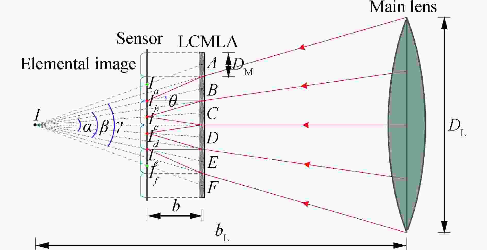
Figure 6. Typical imaging process of the DMC prototype constructed
Since the aperture of each microlens is very small, the angle β satisfying the relation α<β<γ can be taken approximately. According to the triangulation, β = 2θ, a relation between the main lens system and microlenses can be obtained as
where DL and e represent the aperture of the main lens system and LC microlens respectively, and b represents the distance between the sensor and the LCMLA. Therefore, the F/numbers of the main lens system and each microlens should be matched carefully in the plenoptic imaging mode and the chief ray angle (CRA) is calculated to be 4.3°. Although there is no aperture limitation to the main lens system in the planar imaging mode, the aperture is recommended to be the same with that in the plenoptic imaging mode for fast switching between the two imaging modes.
-
According to the imaging architecture constructed, we can expect that two factors affecting imaging resolution of the DMC are the pixel pitch and the radius of Airy disk. A symbol s is used to represent the resolution limit of the DMC, which should be the larger one between the two factors mentioned above. Figure 7 shows part of the image space of the main lens system behind the LCMLA, where points I1 to I5 are five virtual image points formed by the main lens. The cone angles of incident rays towards the five points are approximately equal.
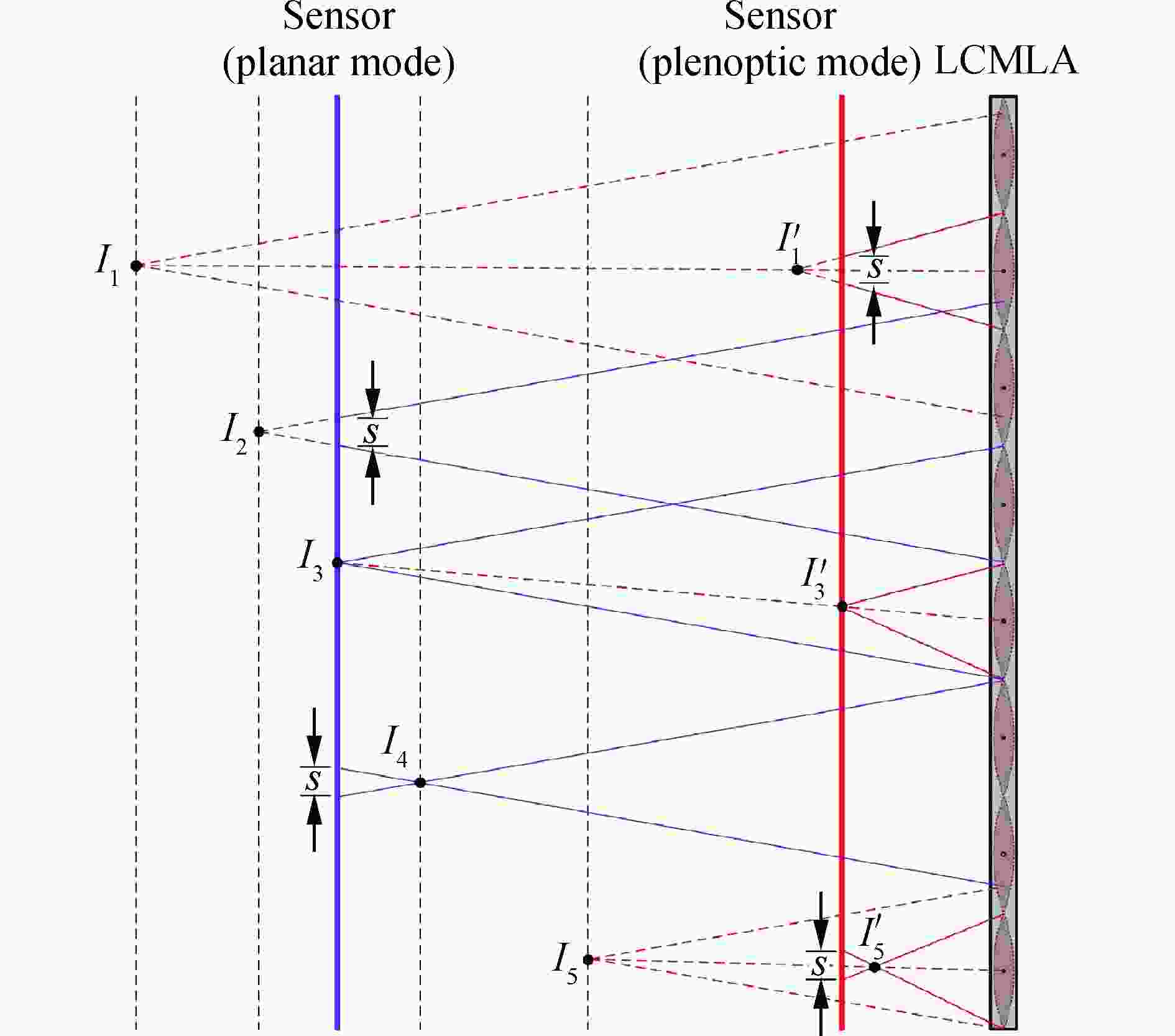
Figure 7. Partial image space of the main lens system that is behind the LCMLA (not in scale)
In the plenoptic imaging mode, only three image points I1, I3, and I5 in the planar mode are considered which are effectively reimaged by corresponding microlenses, as shown by image points I1', I3', and I5'. As shown, point I3' is just on one sensor, while points I1' and I5' are behind and before the sensor and thus two blur spots are formed. If the blur spots are equal to or smaller than s, the spots can still be viewed as focus. Supposing the diameters of points I1' and I3' are equal to s, the refocused range of the microlenses is between the image plane I1 and I5.
While in the planar imaging mode, the rays forming point I3 is focused by the main lens system just onto the sensor, while points I2 and I4 are blur spots with size s. Therefore, the field between the plane I2 and I4 are acceptably sharp in this mode.
It is obvious that the DOF in the plenoptic imaging mode is much wider than that in the planar imaging mode, because the LCMLA not only divides the cone of incident rays but also recompresses the image space of the main lens.
-
Three toy bricks are laid out as objects and imaging experiments in the two imaging modes mentioned above are conducted using the DMC developed. In the plenoptic imaging mode, the screw micrometers of the stage supporting the sensor and the LCMLA, as shown in Fig.4, are set to the same scale at every snapshot to assure the constancy of the DMC once its configuration parameters are determined, because the computation of 3D information of the objects relies on the geometry of the DMC, which will be discussed later.
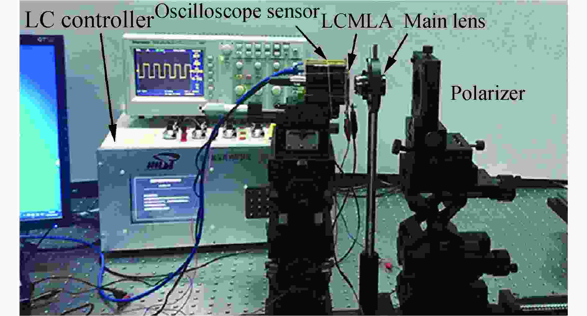
Figure 4. DMC prototype
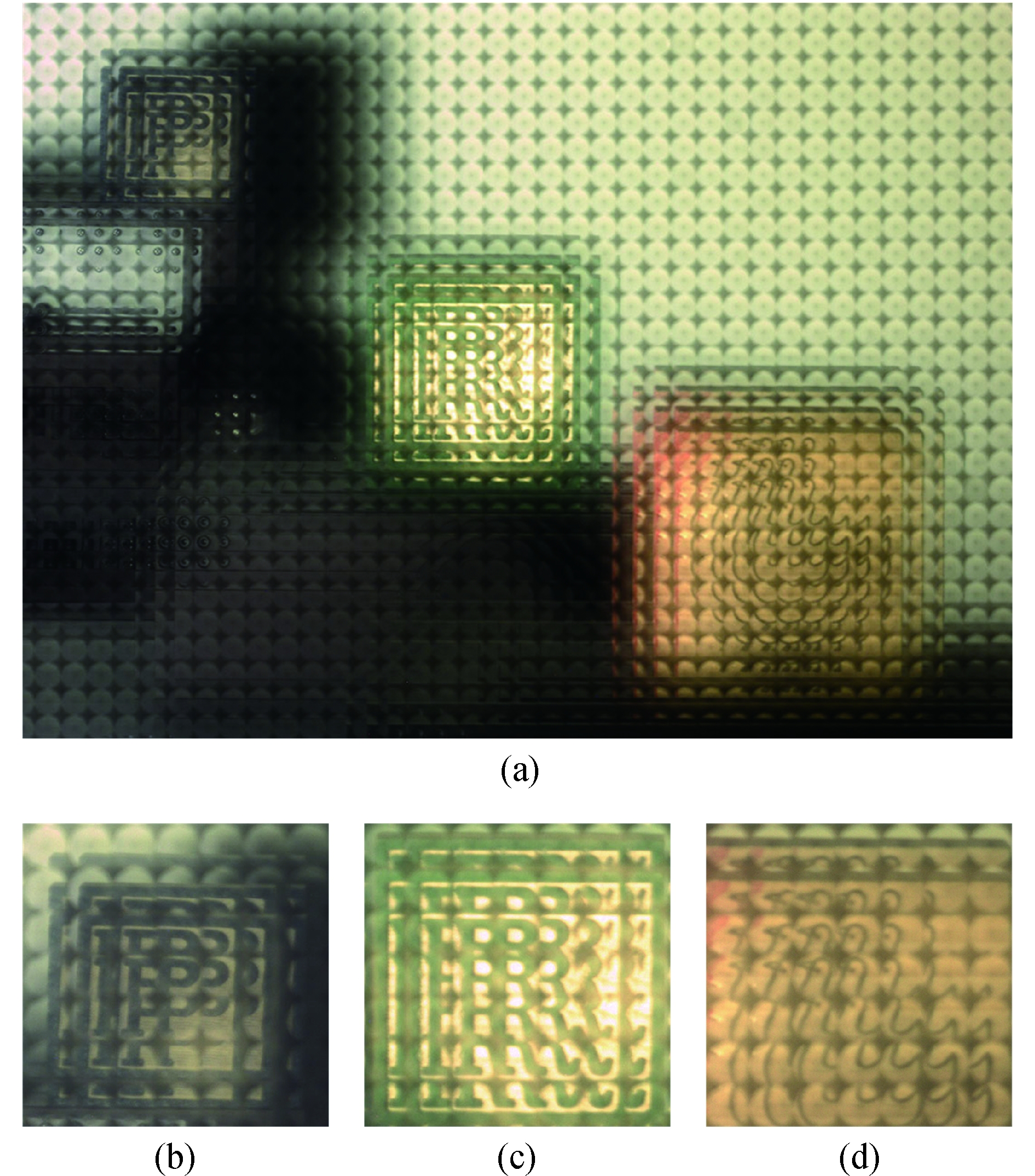
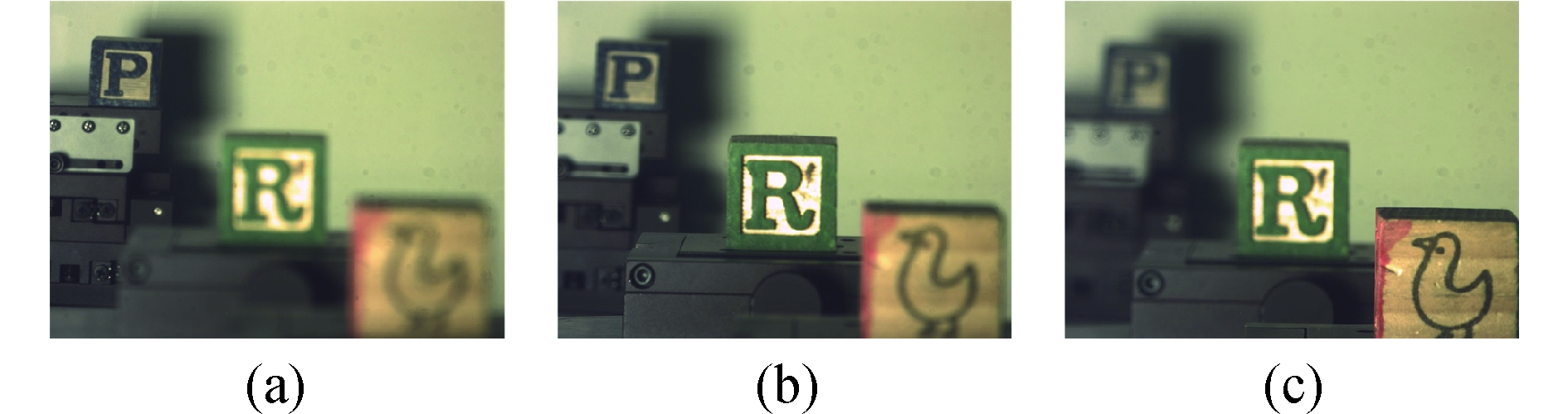
Firstly, the LCMLA is supplied by a voltage signal of ~7.0 Vrms and then the DMC acts as a plenoptic camera, as shown by Fig.8. Figure 8(a) presents a whole image including three objects with different objective distance. The close-ups of three bricks are shown by Fig. 8(b) to Fig.8(d). It can be seen that each microlens only images part of the objective space clearly, due to the wide DOF in the plenoptic mode. When the LCMLA is turned off, the DMC is switched to the planar imaging mode. The objects and the main lens system remain unchanged. Cautiously adapting the back-and-forth micrometer to make it to move along the optical axis direction, the assembly of the sensor and the LCMLA is moved backwards slowly so as to sequentially get the focuses of the bricks.

Figure 8. Plenoptic images. (a) Panorama image, (b) a close-up of the far brick, (c) a close-up of the middle brick, and (d) a close-up of the near brick
Figure 9 shows the planar images of the bricks in the planar imaging mode, which exemplify the narrower DOF of the planar mode than the plenoptic mode.

Figure 9. Typical imaging character of the planar imaging mode including: (a) far brick, (b) middle brick, and (c) near brick
-
Before performing 3D reconstruction, sufficient 3D information must be figured out according to the DMC constructed. The objective distance or depth is a pivotal parameter for achieving fast calculation. To estimate the depth of a virtual object point formed by the main lens system in the plenoptic imaging mode, at least two real image points must be shaped on the sensor. According to the position of the image points originated from the same object point, a geometric relationship between the depth of the object point and its corresponding image point can be set up. Figure 10 presents a typical parameter arrangement for the depth estimation of 3D reconstruction. As shown, the light rays propagating towards the virtual image point I formed by the main lens system are split by two adjacent microlenses and then converged onto the sensor so as to result in two real image points I1' and I2'. The pinhole model is used to determine the position of the real image point. Points O1 and O2 are the projections of the principal points of the two microlenses onto the sensor. Two variables d1 and d2 are defined as the coordinates of the two real image points I1' and I2'. Taking O1 and O2 as the origin points separately, a disparity variable Δd, which is the difference between d1 and d2, can be yielded as

Figure 10. Parameter arrangement for the depth estimation of 3D reconstruction
According to the similar triangle theorem, an equation can be acquired as
where a denotes the object distance with respect to the LCMLA, and can be calculated as
Since the practical values of b and e can be obtained from the configuration of the DMC, the disparity variable Δd is a key factor, which can be measured according to image matching between the elemental images of adjacent microlenses. So far, several image matching algorithms have been developed including the sum of absolute differences (SAD), the sum of squared differences (SSD), and normalized correlation coefficient (NCC). Considering the complexity of matching a small pixel point, a window with an adaptable size is adopted. Figure 11 shows an example based on window matching between two adjacent microlenses according to the NCC method. So, the disparity Δd between the two windows can be measured as 32.2 μm (23 pixels).

Figure 11. Window matching between two adjacent microlenses
-
After determining the depth of a virtual image point formed by the main lens system, the 3D coordinates of corresponding object points can be calculated according to the similar triangle theorem. As shown in Fig.12, the pinhole model is adopted to illustrate the position of an object point P, the virtual image point I, and one real image point I'. The z-axis of the coordinate system is normal to the sensor, whereas x- and y-axis are parallel to the sensor. The coordinates (I 'x, I 'y) of point I' and (Lx, Ly) of principal point L of the microlens can be obtained according to the DMC architecture. The coordinates (Ix, Iy) of point I can be calculated by the equation of
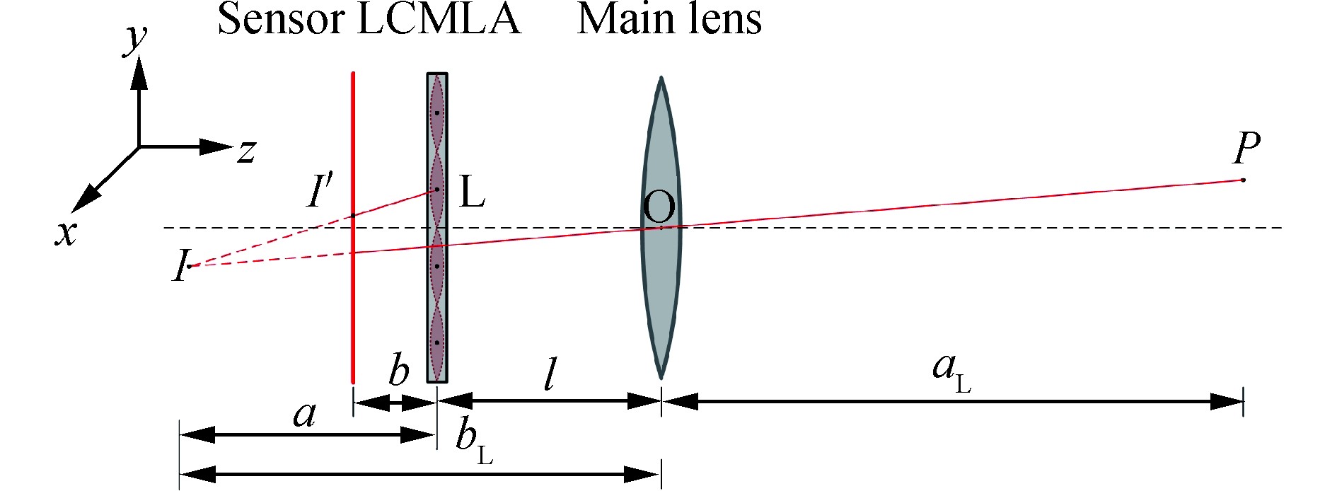
Figure 12. Parameter configuration for 3D positioning
According to the thin lens equation, the objective distance can be figured out by the relation of
where l denotes the distance between the LCMLA and the main lens system. The coordinates (Px, Py) of object point P can also be acquired finally from the equation of
To compute the 3D coordinates of a window setting in the plenoptic imaging mode, the parameters of b, l, and fL should be measured manually. Moreover, to decrease the errors of the results, a thorough calibration must be done to figure out accurate values before the DMC is put into use.
-
After the coordinates of all windows have been calculated, the 3D reconstruction can be performed accordingly. However, the resolution in the plenoptic imaging mode is much lower than that in the planar imaging mode because a portion of the sensor has already been taken up by directional information. To achieve high-resolution 3D reconstruction, each window should be matched with the planar image to find out its sharper clip originated from the same space. In order to improve the correctness of image matching, several adjacent windows coming from the same depth can be synthesized together to form a larger patch.
In our experiments, three bricks with different depths are arranged along the optical axis. We can generate the patches of bricks from their windows and then match them with the planar images processed. Figure 13 shows a typical image matching operation between two modes. As shown in Fig.13(a), the patch of the near brick is rendered from the plenoptic image. Its matching clip of the planar image is shown in Fig.13(b). The lateral resolution between them is 1:5.25.

Figure 13. Image matching between two imaging modes. (a) Patch of the near brick and (b) matching clip of the planar image
-
A high-resolution 3D reconstruction scene of the three bricks using corresponding clips of the planar images is shown in Fig.14. Compared with the plenoptic patches, the lateral resolution of the near, middle, and far brick is improved 5.25, 4.55, and 3.57 times, respectively.
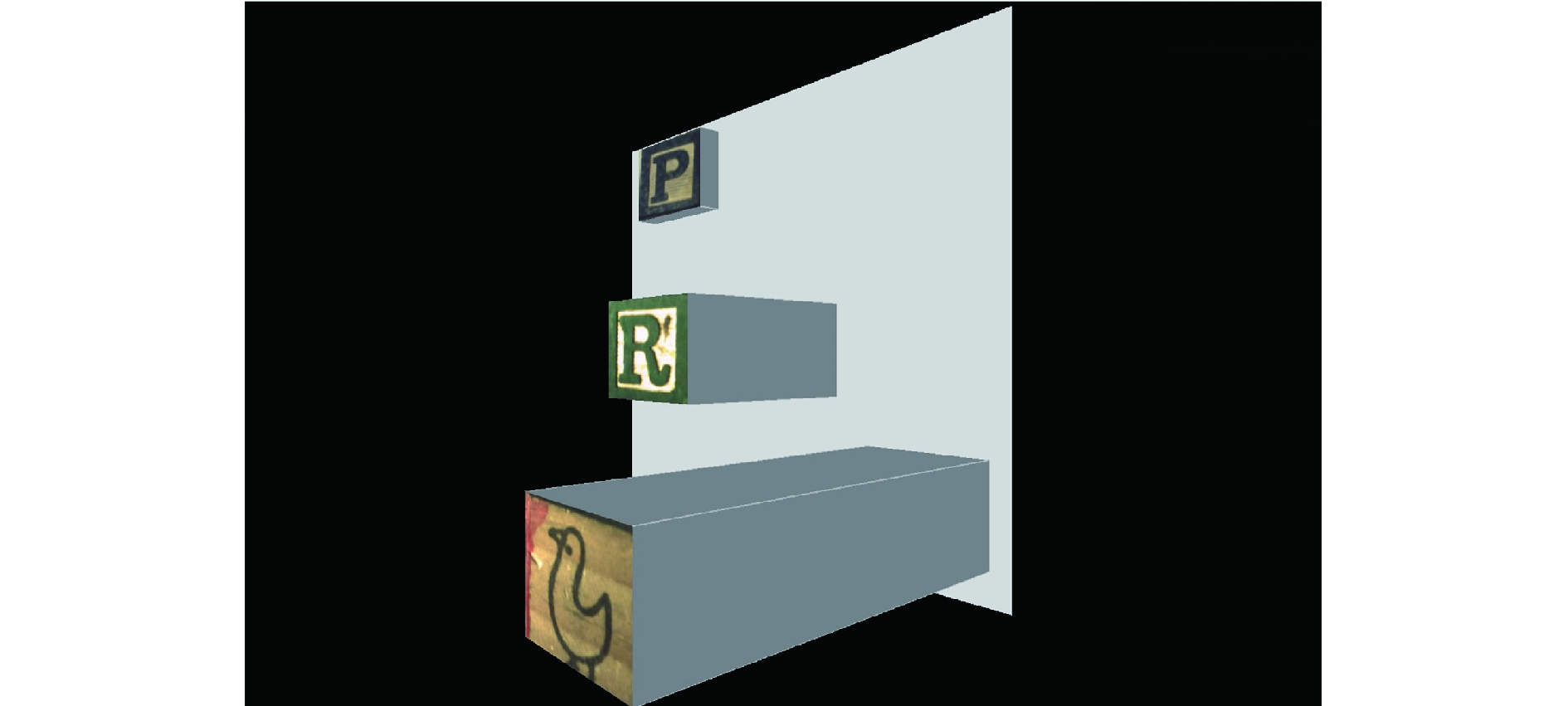
Figure 14. High-resolution 3D pattern reconstruction of the three bricks
-
In this paper, an imaging setup with a dual-mode function including the plenoptic imaging mode and the conventional planar imaging mode, is proposed. Two imaging modes can be switched easily by only turning on or off the voltage signal loaded over the LCMLA of the imaging setup. A camera architecture based on the constructed setup can further perform 3D high-resolution reconstruction through synthesizing 3D data acquired according to the plenoptic imaging mode and planar imaging data. Compared with 3D reconstruction only based on plenoptic imaging, our 3D reconstructive results improve the resolution greatly.
Dual-mode camera using liquid-crystal microlens for high-resolution three-dimensional reconstruction
doi: 10.3788/IRLA20190540
- Received Date: 2020-05-24
- Rev Recd Date: 2020-06-11
- Available Online: 2020-09-22
- Publish Date: 2020-08-28
-
Key words:
- plenoptic imaging /
- liquid-crystal microlens array /
- 3D reconstruction
Abstract: A dual-mode camera (DMC) was proposed based on liquid-crystal microlens array (LCMLA), which could be readily switched between the conventional planar imaging mode and the plenoptic imaging mode through turning on/off the low frequency voltage signal applied on the LCMLA. The LCMLA was fabricated by common UV-photolithography and wet etching. Through coupling the LCMLA with a main lens and a photosensitive sensor array, a DMC prototype was constructed. Experiments were conducted to acquire plenoptic imaging data and corresponding planar imaging data of objects. The issues of the aperture design and the depth of field in the two modes were discussed in detail. A computation method for three-dimensional (3D) information acquisition based on the plenoptic imaging mode was given. A high-resolution 3D reconstruction was implemented by fusing 3D plenoptic data and corresponding 2D high-resolution planar imaging data.


 DownLoad: