


-
近年来,随着各国对航天领域的重视,高精度空间遥感技术得到了极大发展,成像光谱仪能够提供景物连续的光谱图像,是未来遥感技术发展的主流和方向。通过与地球大气中的气溶胶和悬浮颗粒相互作用,非偏振的太阳光其电矢量的平行分量、垂直分量的振幅及相位均发生改变,散射光不再各向同性,因此入射到光学系统中的光线变为部分偏振光[1-4]。光谱仪中的一些关键部件如:光栅、反射镜、分色片、滤光片、狭缝等,均对光线偏振特性比较敏感,造成探测器输出差异,偏振响应的不确定性一定程度上会降低遥感仪器的定标精度,因此,为了准确的测量被测目标特性,必须对仪器的偏振灵敏度进行评估和校正。
除了需对仪器进行实时的测试和标定[5],还需要在设计阶段根据偏振产生的机理,采用相应的方法减小或消除仪器自身的偏振影响,主要通过以下途径:(1)改进相机光学布局,减小光线在各光学元件上的入射角度,同时调整光学元件之间角度关系,使关键光学元件的P光、S光在系统中实现正交补偿[6];(2)对各光学件进行低偏振灵敏度膜系设计[7],包括反射膜、分光膜、透射膜、滤光膜等);(3)根据系统特点,光学设计阶段在光路中加入一个或多个消偏器,降低消偏器后端出射光的偏振特性,这也是最简单有效的方法之一。
小型光谱仪结构较为简单,口径较小,通常可将消偏器加在系统前端以提高系统偏振灵敏度。目前常用消偏器大致有以下几种:旋光型消偏器、Lyot型消偏器、H-V型消偏器(或由两个H-V消偏器组成的双巴比涅型消偏器)等。理论计算可知对于旋光型消偏器,单个晶体楔角需要做到很大(往往十几度甚至二三十度)才能达到较好的消偏效果,在大部分系统中受各种因素限制这种消偏器几乎是不可能应用的;对Lyot型消偏器而言,光谱分辨率要求越高,Lyot消偏器的偏振灵敏度越差,因此Lyot型消偏器在高分辨率光谱仪中应用较少;而H-V型消偏器及双巴比涅型消偏器由于其自身对光谱分辨率不敏感的特点,在光谱设备中应用较多。基于此,文中研究了应用于光栅光谱仪的消偏器的理论特性,并基于理论计算结果研制了一款实用型消偏器。
-
如图1所示,H-V消偏器由两块厚度一定的光楔晶体组成,这两块晶体的晶轴一个为水平方向,另一个为垂直方向。左、右晶体楔角相同、符号相反。

Figure 1. Structure of H-V depolarizer
z轴表示光线传播方向,x‐y平面为消偏器截面,入射光沿光轴z方向垂直入射,由于双折射特性,光线进入晶体1后分解为o光和e光,由于两块晶体的光轴相互垂直,晶体1出射的光进入晶体2后o光变为e光,e光变为o光。
则在坐标x处出射光的o光和e光两分量的相位延迟(即入射光通过H-V消偏器的相位延迟)为[8]:
式中:λ为波长;no,ne分别为晶体o光和e光的折射率;x为归一化光瞳坐标;R为光瞳半径;t1、t2为两个晶体的中心厚度。
H-V消偏器的Muller矩阵为:
通常t1=t2,公式(1)可简化为:
将其带入H‐V消偏器穆勒矩阵,再对入瞳面积分得Muller矩阵(通常入瞳为圆形):
式中:J1(δ)为一阶贝塞尔函数。令矩阵参数η=2J1(δ)/δ,可得典型波长下,η与相位δ的变化关系如图2所示。

Figure 2. Relationship between matrix parameter and phase
结合图2及公式(1)可以看出如下规律:
(1)波长越短相位δ越大,H-V消偏器性能越好;
(2)一定范围内,楔角β越大δ越大,H-V消偏器性能越好;
(3)光瞳半径R越大δ越大,H-V消偏器性能越好;
(4)当相位延迟量大于5.8π时,矩阵参数绝对值小于0.02,能够满足大部分应用场合。通常光学系统确定后,波长及光瞳半径已经确定,可根据需要选择合适的楔角及晶体类型以满足应用需求。
由公式(4)可知,不同类型的偏振光经H-V消偏器后,其残余偏振态有不同的形式,表1给出了典型偏振光经H-V消偏器后残余偏振度计算结果。
可知单个H-V消偏器不能对所有类型偏振光起到消偏效果,尤其对水平和垂直线偏光没有消偏作用。在使用上有一定局限性。
Types of incident light Stokes expression of incident light Stokes expression of output light DOP Horizontal-linear polarized light (1,1,0,0)′ (1,1,0,0)′ 1 Vertical-linear polarized light (1,−1,0,0)′ (1,−1,0,0)′ 1 45° linear-polarized light (1,0,1,0)′ (1,0, η,0)′ η −45° linear-polarized light (1,0,−1,0)′ (1,0,− η,0)′ η Left-rotated circular-polarized light (1,0,0,1)′ (1,0, 0, η)′ η Right-rotated circular-polarized light (1,0,0,−1)′ (1,0, 0, −η)′ η Table 1. Polarization degrees of a H-V depolarizer
-
针对H-V消偏器理论,将两个H-V消偏器45°旋转组合成一个双巴比涅型消偏器即可对各个方向的偏振光消偏,图3为双巴比涅型消偏器结构示意图。
45°旋转的结构使得对于第一块H-V消偏器(简称HV-1)为水平或垂直的线偏振分量可由第二块H-V(简称HV-2)消偏器进行退偏。HV-2的Muller矩阵可通过HV-1的Muller矩阵坐标旋转得到。双巴比涅消偏器的Muller矩阵为:
对其在光瞳面积上积分,可得平均穆勒矩阵如下所示:
式中:
从Muller矩阵表达式可知,相位δ与消偏效果紧密相关。

Figure 3. Structure of double Barbinet depolarizer
-
以石英晶体为例,分析残余偏振度与波长、楔角、入射光瞳面尺寸、入射光偏振角之间的关系。
-
图4为此时双巴比涅消偏器残余偏振度与波长的关系,从整体变化趋势上可以看出波长越短越容易消偏,随着波长变化,残余偏振度的值在极大与极小之间呈现震荡趋势。

Figure 4. Relationship between residual polarization degree and wavelength
-
图5给出在特定波长下,双巴比涅消偏器残余偏振度与晶体楔角β的关系,从曲线的变化趋势可以看出,楔角β越大,残余偏振度越小,消偏效果越好。但在小型光谱仪中,双巴比涅消偏器的单个晶体厚度往往较小,为追求高消偏性能一味增大楔角会导致晶体边缘较薄,加工过程容易崩边,晶体光学面形不易控制,此外大的楔角还会造成较大的双像分离[9],会对成像质量产生影响。因此对系统偏振分析时需综合考虑上述因素,选择合适的晶体楔角。
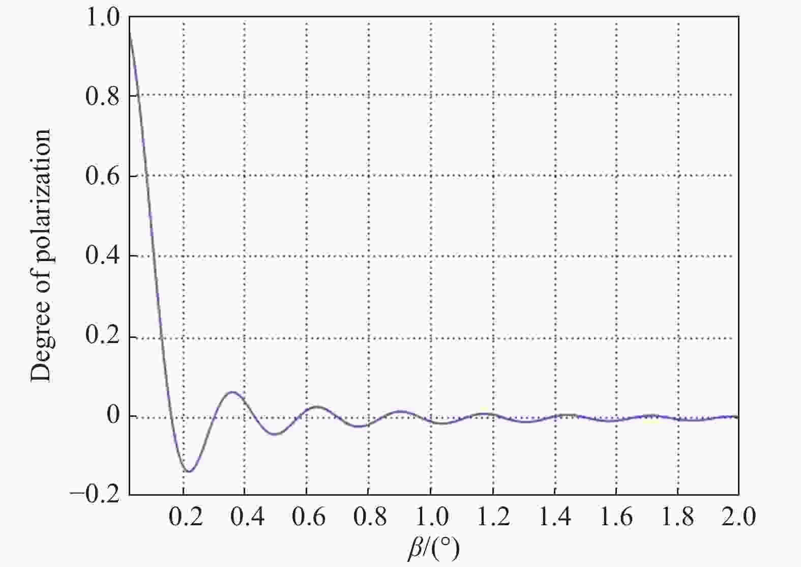
Figure 5. Relationship between residual polarization degree and β
-
图6分别给出400 nm和900 nm工作波长时,特定楔角下双巴比涅消偏器残余偏振度与入射面光瞳半径R的关系。从曲线趋势可以看出,消偏器有效入射光瞳面越大,消偏效果越好。

Figure 6. Relationship between residual polarization degree and radius
-
一般情况下,假设入射光为振动方向与x轴夹角为φ的线偏振光,此时光线相应的输入和输出斯托克斯矩阵分别如下:
则消偏器的残余偏振度可表示为:
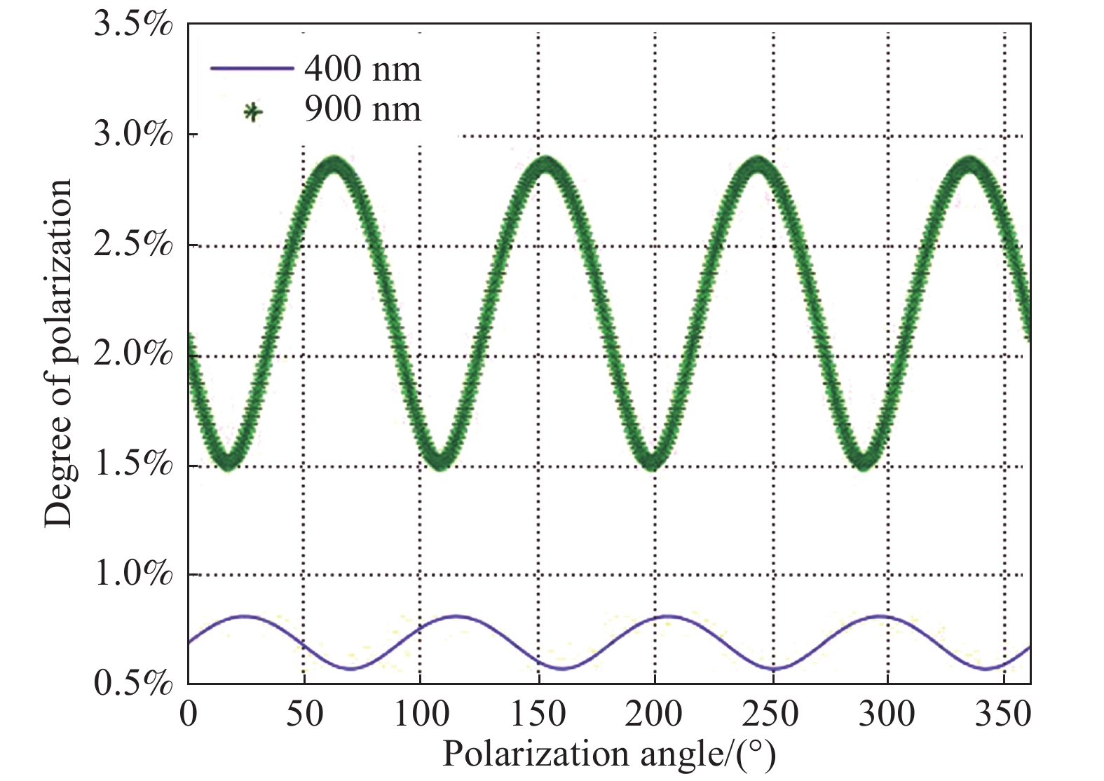
给定楔角及光瞳半径,在工作波长分别为400 nm和900 nm时得到双巴比涅消偏器的残余偏振度与入射偏振角的曲线如图7所示,从图中可以看出波长一定时,随着入射偏振角的变化,消偏器的残余偏振度在一定范围内周期变化,波长越短残余偏振度越小。

Figure 7. Relationship between residual polarization degree and polarization angle
从上述分析可以看出,不管入射光偏振态如何,双巴比涅消偏器均可对其起消偏作用,因此在光谱仪中得到广泛应用,并且双巴比涅消偏器在系统装调时无需考虑晶体楔角及光轴与光谱仪中光栅刻线、狭缝安装方向、反射镜等光学元件之间的位置关系,大大简化了系统装调难度。
-
基于上述理论分析文中研制了一款应用于某光谱仪的双巴比涅型消偏器,基底材料为石英晶体,工作波长0.4~0.9 μm,结合空间结构布局及光学设计结果,消偏器光瞳有效口径为Φ20.6 mm,单个晶体中心厚度为2 mm,胶合后中心厚为8 mm,晶体楔角为0.6°,图8为研制的消偏器实物及根据实测光谱计算得出的消偏器残余偏振度,可以看出,消偏器残余偏振度≤3%满足指标,整体趋势为波长越短偏振度越小。0.4 μm端残余偏振度有较大起伏是因为选用的晶体间粘接胶在该波长附近吸收较大,P光、S光在该波段透过率较低所致,其余位置偏振度有较小起伏主要受粘接胶吸收率及测试设备误差影响。双巴比涅消偏器楔角产生的最大像分离计算公式为
$(\sqrt 2 + 2)f*\tan \beta $ [10],表2所示为计算得到的不同波长对应像分离列表,最大像分离出现在0.4 μm处,此时像分离为25.4 μm,探测器有效像元尺寸为104 μm×104 μm,像分离值小于(1/3)×104 μm,可以认为对系统MTF影响较小。
Figure 8. Real object and measured polarization sensitivity of depolarizer
Wavelength/nm |ne-no| HV_s/μm DB_s/μm 400 0.009 562 1 7.450 01 25.435 88 500 0.009 259 5 7.214 25 24.631 00 600 0.009 092 9 7.084 40 24.187 65 700 0.008 984 1 6.999 61 23.898 18 800 0.008 903 0 6.936 50 23.682 68 900 0.008 836 2 6.884 43 23.504 93 Table 2. Imaging separation of different wavelengths
-
为减小仪器偏振效应,在光谱仪中适当位置加入一组或多组消偏器是一种简单有效的手段。基于矩阵光学理论,文章分析了H-V型消偏器和双巴比涅型消偏器偏振灵敏度的相关表达式,进一步深入分析得出如下结论:
(1) H-V型消偏器对水平和垂直入射的线偏光没有消偏作用,其使用条件有一定局限性;
(2)对双巴比涅消偏器而言,在一定范围内,波长越短、楔角越大、有效光瞳半径越大,消偏效果越好;
(3)双巴比涅消偏器对任何入射形式的偏振光都能起到较好的消偏效果,其消偏效果与光谱分辨率无关,且安装形式简单,因此在光谱仪中得到广泛应用。
文章最后结合某光栅光谱仪的需求,根据理论分析设计并研制了一款双巴比涅型消偏器,在0.4 ~0.9 μm工作波长范围内,消偏器残余偏振度优于3%,并且双像距满足使用要求,工程实践性较强。
Study on depolarizers applied for a grating spectrometer
doi: 10.3788/IRLA20190544
- Received Date: 2019-11-10
- Rev Recd Date: 2020-03-14
- Available Online: 2020-07-23
- Publish Date: 2020-07-23
-
Key words:
- depolarizer /
- quartz crystal /
- Muller matrix /
- residual polarization
Abstract: The image quality of the grating spectrometer is often affected by the polarization characteristics of the incident light. In order to solve this problem, a depolarizer is usually added to the spectrometer to reduce the polarization response of the instrument. The birefringence property of the crystalline material can produce a depolarization effect on the optical principle, therefore it is often used to process into various types of depolarizers. Based on the principle of the matrix optics, the Muller matrix and residual polarization theoretical expression of a H-V depolarizer and a double Barbinet depolarizer were deeply discussed. The relationship among residual polarization of a double Barbinet depolarizer and working wavelength, its wedge angle, entrance pupil diameter and incident light polarization angle was given respectively. Based on these theories, a double Barbinet depolarizer applied for a grating spectrometer was developed. It could be obtained by calculation that when the wedge angle and the pupil diameter of the double Barbinet depolarizer was 0.6° and 20.6 mm respectively, the residual polarization of the depolarizer was better than 3% in the wavelength range of 0.4-0.9 μm. What’s more, the double image distance met the application requirements, so it can be widely used in engineering practice.


 DownLoad: