


-
离轴反射系统因其显著的宽光谱、高透过率、无色差的优点,被广泛应用于诸多成像领域[1]。为避免光线遮拦,离轴系统通常缺失旋转对称性,进而引入离轴像差。常规的旋转对称表面,如球面、非球面,校正这类像差的能力较弱,而光学自由曲面具有非旋转对称和多自由度性能,适用于校正此类像差。近几年来,自由曲面广泛应用于各类离轴反射成像系统[2],美国罗切斯特大学设计了一个非制冷型短焦红外的紧凑型自由曲面离轴三反光学系统[3],清华大学提出了具有小F数自由曲面离轴三反系统的设计方法[4],中国科学院长春光学精密机械与物理研究所孟庆宇采用XY多项式自由曲面设计了一款
$30^{\circ }\times 1^{\circ} $ 的大线视场角离轴三反系统[5],长春理工大学姜晰文设计了一款$3.663^{\circ }\times 2.931^{\circ} $ 的制冷型离轴三反系统[6],使用了Zernike多项式自由曲面面型。与非制冷型系统相比,制冷型系统的灵敏度更高,响应速度更快,探测距离更远[7],但针对制冷型探测器,冷光阑限制了系统视场角的扩大。在制冷型离轴反射光学系统中,同时实现大视场和大相对孔径比较困难。光学系统设计中,直接获取一个接近目标的初始结构是很有必要的,不但可以降低对高水平设计经验的要求,而且能节约大量的软件优化设计时间。文中基于矢量像差理论和高斯矩阵光线追迹方法,利用遗传算法迭代出最小误差函数,采用光瞳离轴和视场离轴,获得接近目标的初始结构,实现了大视场大相对孔径的成像光学系统设计。最终设计的自由曲面制冷型离轴反射光学系统具有良好的成像质量,满足目前光学系统的加工、检测、装调能力,对制冷型离轴反射光学系统的设计有一定的参考价值。
-
矢量像差理论由Shack和Thompon提出并由Thompson[8]完善,可用来描述非旋转对称系统的像差场分布规律,适用于离轴反射系统的像差关系。根据矢量像差理论,光瞳离轴、视场离轴与其对应的轴对称光学系统的关系[9]如公式(1)、(2)所示:
式中:
${H_{Aj}}$ 为倾斜偏心后表面上的有效视场;$H$ 为轴对称光学系统的视场矢量;${\sigma _j}$ 为第$j$ 面上的偏移矢量;${\rho ^{'}}$ 为轴对称光学系统的孔径矢量;$\rho $ 为离轴光学系统的孔径矢量;${P_1}$ 为光瞳的偏心矢量;$B$ 为光瞳在离轴光学系统和同轴光学系统中的缩放比,$B = {{{R_2}} /{{R_1}}}, {P_1} = {P /{{R_1}}}$ ,其中,${R_1}$ 为轴对称光学系统的光瞳半径,${R_2}$ 为离轴光学系统的光瞳半径。同轴反射光学系统的矢量波像差系数可以表示为:
式中:
${W_{040j}}{\text{、}}{W_{131j}}{\text{、}}{W_{222j}}{\text{、}}{W_{220j}}{\text{、}}{W_{311j}}$ 依次是同轴光学系统的初级球差、彗差、像散、场曲、畸变。根据公式(1)~(3),离轴反射系统的初级波像差系数由公式(4)表示,球差系数
${C_1}$ 和场曲系数${C_4}$ 为标量、彗差系数${C_2}$ 、像散系数${C_3}$ 和畸变系数${C_5}$ 为矢量[10]。离轴反射光学系统的初级波像差是同轴反射光学系统的初级波像差和位移矢量的函数,根据反射矩阵和传递矩阵获取主光线和边缘光线的近轴光线追迹数据,进而获得同轴光学系统的初级波像差系数[11-12]。
使公式(4)中各像差系数的绝对值之和最小,计算出离轴光学系统的初级波像差系数,由于离轴光学系统是非旋转对称系统,单独的中心视场点的成像质量不能代表整个系统的成像性能,所以构造评价离轴反射系统性能的误差函数,由全局视场的初级像差系数组成,误差函数如式所示:
式中:
${\omega _i}$ 表示各个波像差系数的权重因子${\left\| {} \right\|_1}$ 为1-范数。公式(6)将公式(5)表达成离散点拟合的形式,更方便计算误差函数,其中N为选取的视场数量。
根据近轴光线追迹数据,可以计算系统的焦距
${f^{'}}$ 如公式(7)所示,后截距${d_k}$ 如公式(8)所示:光线离开光学系统的最后一个表面与系统孔径光阑的距离L为:
为满足制冷型离轴反射系统冷光阑效率达到100%,需要使探测器冷屏和光学系统出瞳大小和位置完全相同,则可以在误差评价函数中构造以下条件:
最终构造的误差评价函数包括所有选取的视场像差系数、焦距大小和冷光阑匹配条件,如公式(11)所示:
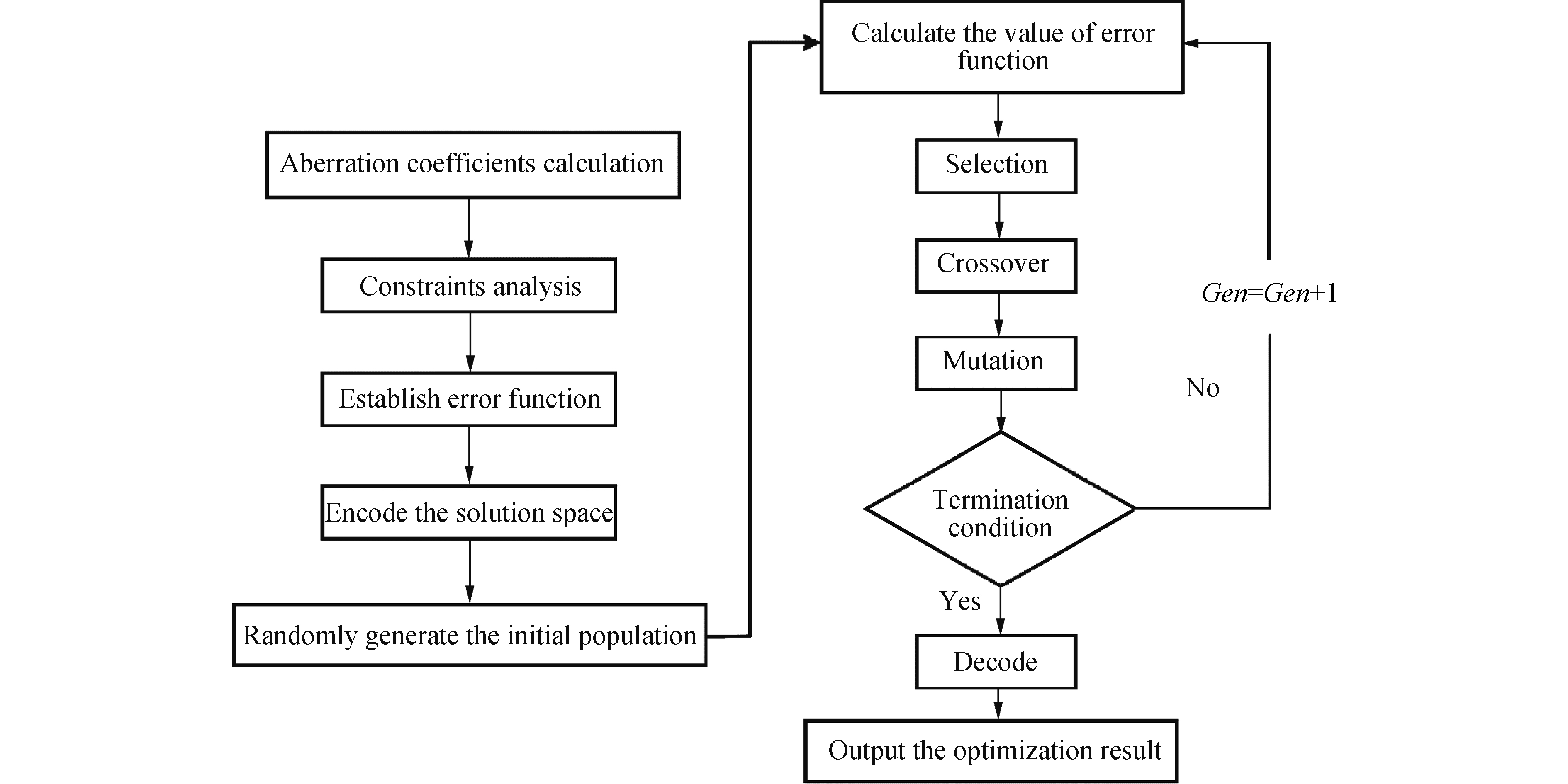
误差函数Q越小,代表光学系统总体成像质量越高,文中选用遗传算法多次迭代计算得出最小值。遗传算法是一种高效率的全局搜索计算方法,通过选择、交叉、变异,逐渐搜索到接近问题最优解的区域。与传统优化方法相比,其最大的区别在于遗传算法并不是从单一解或局部区域开始迭代,而是在问题可能的解空间内进行全局搜索与计算,覆盖范围广,有利于择取最优解[13]。通过遗传算法对误差函数的优化过程如图1所示,首先根据系统各项像差系数、焦距以及冷光阑匹配条件建立误差函数,编码解空间范围并产生初始种群,计算多组误差函数数值,经过选择交叉变异循环优化,从多组解空间多次迭代计算出误差函数最小的最优解,解码即可得到光学系统的初始结构参数。将其输入光学设计软件CodeV中,做为离轴反射光学系统的初始结构的起点进行下一步优化。

Figure 1. Flow chart of design process
-
自由曲面的描述方法分为参数描述法和多项式描述法,参数法不能用多项式描述,如贝塞尔曲面、B样条曲面[14],因为其描述的面型没有固定的表达形式,在加工和检测过程中会有诸多问题。多项式法描述的面型比较平滑,而且精度较高,目前发展较为成熟,可以加工和检测并投入使用。在成像光学系统中,通常使用Zernike多项式和XY多项式表达自由曲面,其中,Zernike多项式在单位圆内正交,各项像差互不影响,XY多项式与Zernike多项式之间可以互相转换,即可表达各项像差,又能直接对应目前的数控车床加工形式,使用XY多项式,增大光学系统设计自由度,可以有效扩大视场角,校正离轴像差,易于加工和生产。
XY多项式的表达形式:
其中,
式中:
$c$ 为圆锥曲率;$k$ 为圆锥常数;${C_j}{x^m}{y^n}$ 为的XY多项式的第$j$ 项,$m$ 和$n$ 为非负整数,分别代表$x$ 和$y$ 的阶数,在光学设计软件中,XY多项式阶数通常取十阶以内,用来表达自由曲面面型,即$m + n < 10$ [15]。在使用自由曲面优化离轴反射光学系统时,要根据光学系统所包含像差情况,优化自由曲面中能平衡像差的表达式系数。Zernike多项式可以直观描述光学系统像差,将XY多项式与Zernike多项式对应起来,可以在使用XY多项式作为优化变量时准确校正系统像差。现整理出Zernike多项式和XY多项式分别在极坐标系和笛卡尔坐标系下表现形式,并在表1中描述其与Seidel像差的对应关系。表1中
${Z_i}$ 为Zernike多项式系数,${T_i}$ 为XY多项式系数。Term Zernike
polynomialXY polynomial Corresponding aberration type 1 $1$ $1$ Piston(constant) ${Z_1}$ ${T_1}$ 0th order in wavefront 2 $\rho \cos \theta $ $X$ Distortion-tilt(x-axis) ${Z_2}$ ${T_2}$ 2nd order in wavefront 3 $\rho \sin \theta $ $Y$ Distortion-tilt(y-axis) ${Z_3}$ ${T_3}$ 2nd order in wavefront 4 $2{\rho ^2} - 1$ $2\left( {{x^2} + {y^2}} \right) - 1$ Defocus ${Z_4}$ ${T_1} + {T_4} + {T_6}$ 2nd order in wavefront 5 ${\rho ^2}\cos \left( {2\theta } \right)$ ${x^2} - {y^2}$ Astigmatism, primary
(axis at 0°or 90°)${Z_5}$ ${T_4} + {T_6}$ 4th order in wavefront 6 ${\rho ^2}\sin \left( {2\theta } \right)$ $2xy$ Astigmatism, primary
(axis at ±45°)${Z_6}$ ${T_5}$ 4th order in wavefront 7 $\left( {3{\rho ^2} - 2\rho } \right)\cos \theta $ $3{x^3} + 3x{y^3} - 2x$ Coma,Primary(x-axis) ${Z_7}$ ${T_2} + {T_7} + {T_9}$ 4th order in wavefront 8 $\left( {3{\rho ^2} - 2\rho } \right)\sin \theta $ $3{x^2}y + 2{y^3} - 2y$ Coma,Primary(y-axis) ${Z_8}$ ${T_3} + {T_8} + {T_{10}}$ 4th order in wavefront 9 $6{\rho ^4} - 6{\rho ^2} + 1$ $6{x^4} + 12{x^2}{y^2} - 6{x^2} + 6{y^4} - 6{y^2} + 1$ Spherical aberration,Primary ${Z_9}$ ${T_1} + {T_4} + {T_6} + {T_{11}} + {T_{13}} + {T_{15}}$ 4th order in wavefront Table 1. Zernike polynomials and XY polynomials correspond to aberration relations
-
为实现100%冷光阑匹配,将制冷型探测器孔径光阑设置于光学系统的出瞳上,最终设计的光学系统视场角为X方向[−4°,+4°],Y方向[2.5°,7.5°]的,其具体参数如表2所示。
Parameter Specification Wavelength range/μm 8-12 Focal length/mm 400 F-number 2 Field of view $8^{\circ }\times 5^{\circ} $ Pixel size/μm 30 Table 2. Optical system specification
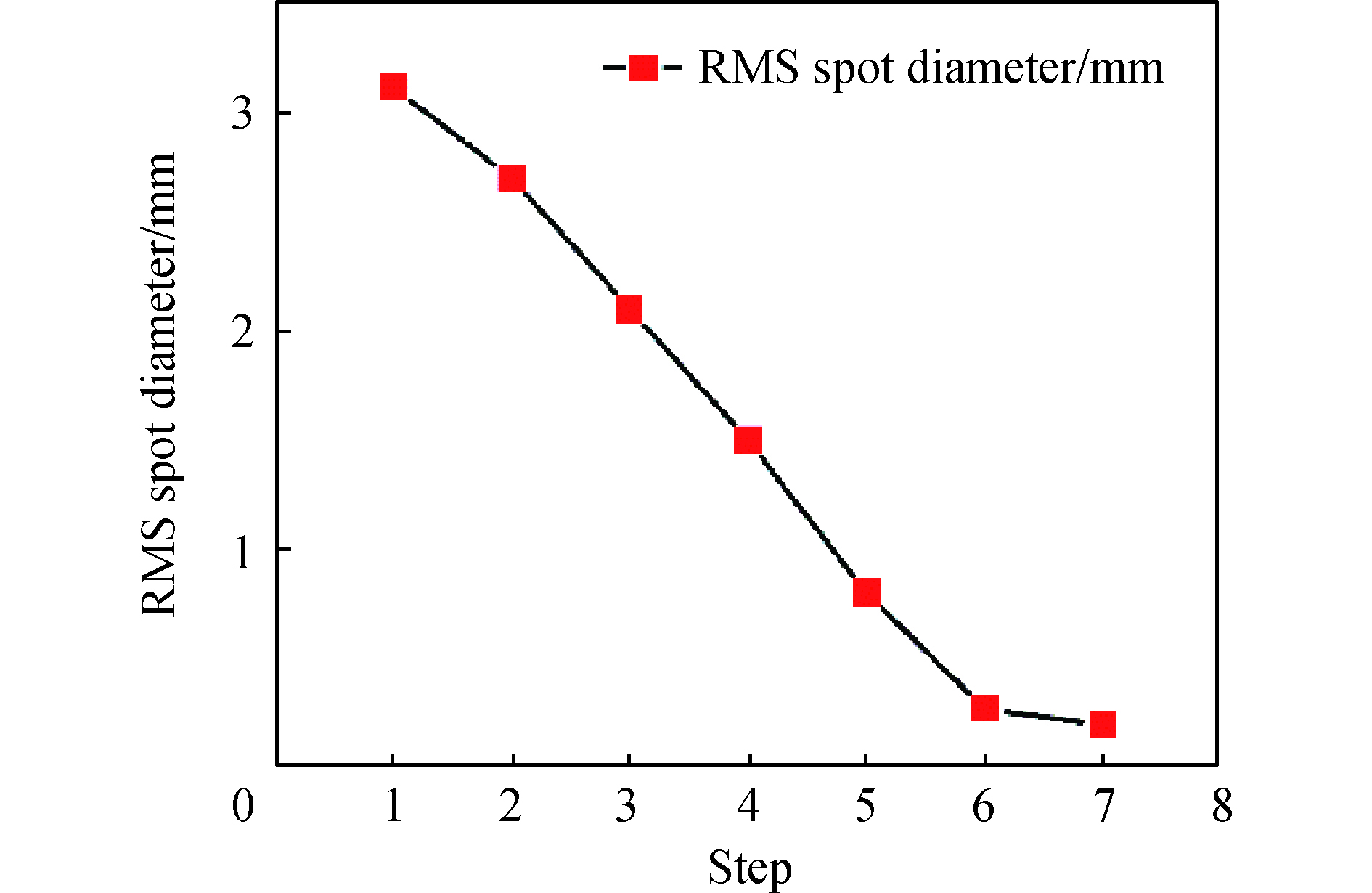
避免离轴反射系统结构发生光线遮拦,在构造误差评价函数时需合理配置视场和孔径的离轴量。求解的初始结构视场角为X方向[−2.5°,+2.5°],Y方向为[2.5°,7.5°]的二次曲面离轴反射光学系统,为了在整个视场范围内获得比较好成像质量,选取一半视场范围内的9个视场点:(0°, 2.5°), (0°, 5°),(0°, 7.5°), (1.5°, 2.5°), (1.5°, 5°), (1.5°, 7.5°),(2.5°, 2.5°), (2.5°, 5°), (2.5°, 7.5°)。利用遗传算法对构造的误差函数进行迭代计算,得到最小值。解空间的参数范围和求解结果如表3所示,表中d为镜片间隔,r为曲率半径,k为二次项系数,
$\alpha $ 为倾斜角度。求解系统的点列图均方根直径变化趋势如图2所示。
Figure 2. Change trend of RMS diameter of spot diagram
Parameter Range Result d1/mm [−250,−100] −201.4271 d2/mm [100,250] 210.6225 r1/mm [−800,−50] −780.0523 r2/mm [−800,−50] −115.2459 r3/mm [−800,−50] −279.4206 k1 [−10,10] 9.0266 k2 [−10,10] 2.5360 k3 [−10,10] 0.1883 α1/(°) [10,30] 15 α2/(°) [10,30] 25.0181 α3/(°) [10,30] 10.0006 Table 3. Ranges of configuration parameters and optimization result
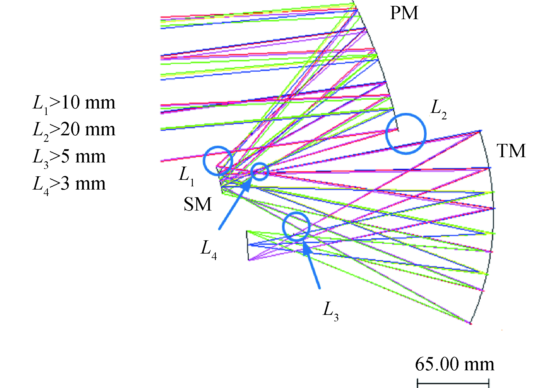
初始的离轴反射光学系统结构,具有比较好的成像质量,利用光学设计软件对初始光学系统进行优化,为避免光线遮拦和杂散光,须严格控制系统中可能出现的光线遮挡或产生干涉的位置距离,图3详细说明了间隔的约束范围。使用XY多项式描述的自由曲面对系统进行优化时,保证系统关于YOZ面对称,只使用含有x偶次项的多项式,先选取只含有y的参数项,再加上与x偶次幂相关的参数项作为变量,优化过程中同时扩大X方向视场角,最终实现
$8^{\circ }\times 5^{\circ} $ 的大视场制冷型离轴反射系统,扩大视场过程中结构和像质变化情况如图4所示。从图4(c)中可以看出,最终系统结构紧凑,点列图中各视场弥散斑直径最大的是24.779 μm,小于一个像元尺寸。
Figure 3. Interval constraint range

Figure 4. In-progress and final results for design of the initial configuration. (a) Initial system; (b) Results for system construction using Φ(X1, Y1); (c) Final result
离轴反射系统的最大RMS波像差为0.056λ(λ=9 μm),平均RMS波像差为0.037λ(λ=9 μm),如图5所示。光学调制传递函数如图6所示,调制传递函数接近衍射极限,光学调制传递函数在奈奎斯特频率(16 lp/mm)大于0.33,有良好的成像质量。图7中全视场范围内80%的能量都集中在直径为0.06 mm的包围圆内,表明光学系统80%以上的能量都集中在探测器2个像元内,系统的能量集中度较高。

Figure 5. Field map of RMS wavefront error for final system

Figure 6. MTF for the final system

Figure 7. Encircled energy distribution of all field
根据以上的分析结果可以看出:自由曲面的应用有效校正了大视场离轴三反系统的像差,在
$8^{\circ }\times 5^{\circ} $ 的大视场下,系统能量集中度高,有良好的成像质量。为了更直观地描述出自由曲面面型,根据光学系统最终的XY多项式面型系数,结合CodeV软件中光线追迹数据与Matlab软件连接,绘出系统中自由曲面面型,如图8所示。由图可见,系统中三个自由曲面面型变化比较平缓,没有局部凸起,适于目前的加工水平。对自由曲面的检测通常采用非球面检测的方法,其中计算全息检测法CGH (Computer-Generated Hologram)得到了广泛的应用[16],针对本系统中的三个自由曲面面型,适用于计算全息检测方法,加工难度和误差较小,可以达到较高的检测精度。

Figure 8. (a) PM 3D free-form surface; (b) SM 3D free-form surface; (c) TM 3D free-form surface
-
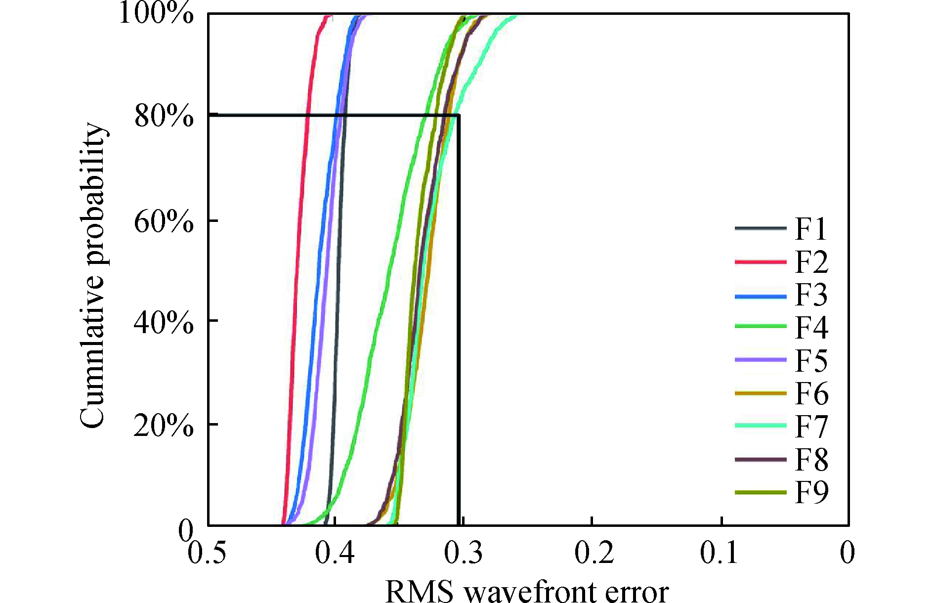
反射系统的公差主要包括制造公差和装调公差,制造公差包括顶点曲率半径的加工公差(△R)、二次曲面常数项公差(△K),RMS面型公差,装调公差包括在X、Y、Z 3个方向的位移公差、绕X轴和Y轴的旋转公差。为保证系统在有效视场内有良好得成像质量,根据现有的加工、装调能力,用蒙特卡罗方法做1 000次公差分析概率统计,以奈奎斯特频(16 lp/mm)处的MTF作为衡量系统性能标准。公差分配结果如表4所示,表5为各概率下每个视场的详细MTF变动表现,系统在奈奎斯特频率(16 lp/mm)处的 MTF变化曲线如图9所示,从图9公差概率曲线可以直观看出:全视场MTF有80%的概率大于0.3。在装调过程中,可以通过补偿器和计算机辅助安装,自由曲面面型利用CGH方法检测,易于实现高精度自由曲面光学系统的应用。
Surface △R/mm △K RMS surface error(λ=9 μm) Displacement Tilt X/μm Y/μm Z/μm X/(″) Y/(″) Z/(″) PM 0.02 0.10% 1/50λ 20 20 25 30 30 20 SM 0.05 0.05% 1/40λ 40 40 20 20 20 20 TM 0.05 0.10% 1/50λ 20 20 20 20 20 30 Table 4. Tolerances distribution of the system
Cumulative probability Change in MTF F1 F2 F3 F4 F5 F6 F7 F8 F9 50.0% 0.002 4 0.004 3 0.004 6 0.010 5 0.006 4 0.012 8 0.015 6 0.007 6 0.005 4 84.1% 0.012 7 0.012 5 0.017 4 0.036 8 0.017 7 0.024 5 0.038 9 0.026 3 0.024 7 97.7% 0.018 5 0.025 6 0.029 8 0.073 7 0.028 8 0.039 7 0.062 2 0.045 0 0.031 6 99.9% 0.022 4 0.037 8 0.052 5 0.103 0 0.048 4 0.068 5 0.098 4 0.063 7 0.046 7 Table 5. Tolerances performance of all field
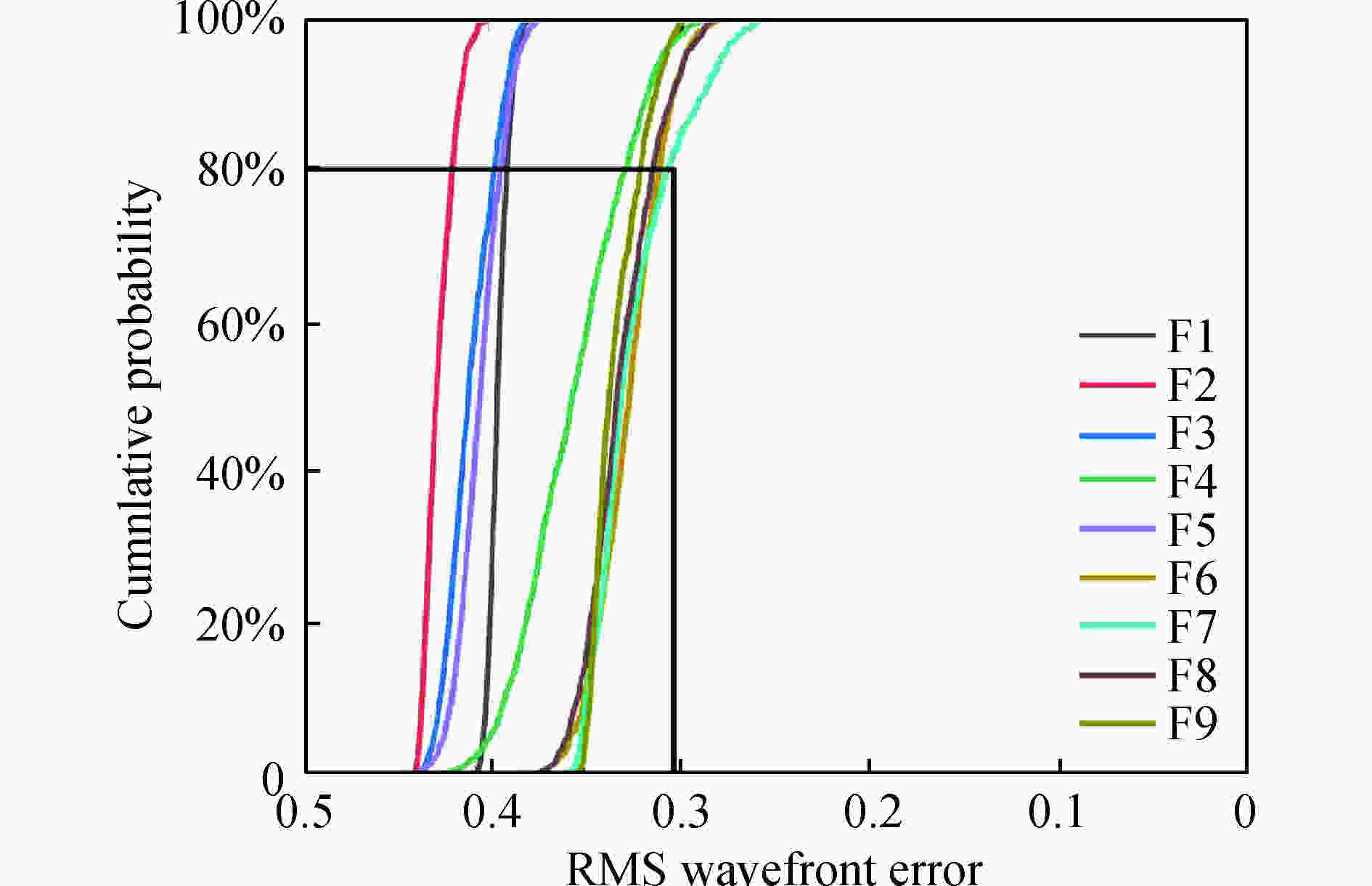
Figure 9. Tolerance probability curve
-
文中通过使用视场离轴和孔径离轴,约束系统焦距和冷光阑位置,结合矢量像差理论和遗传算法,采用XY多项式描述的自由曲面面型设计了一款大视场大相对孔径的制冷型离轴反射成像光学系统。迭代计算的初始结构为二次曲面面型,有较好的成像质量,采用XY多项式描述的自由曲面有针对性的校正系统像差,优化过程中同时扩大视场,最终得到应用于长波红外制冷型探测器的自由曲面离轴三反光学系统,系统成像质量良好,焦距400 mm,F数2,视场角
$8^{\circ }\times 5^{\circ} $ ,平均RMS波像差为0.037 054λ(λ=9 μm),能量集中度高,实现100%冷光阑效率,光学系统公差合理,对高分辨率、大视场的制冷型空间光学系统设计有一定的参考价值。
Design of the freeform imaging system with large field of view and large relative aperture
doi: 10.3788/IRLA20200005
- Received Date: 2020-01-25
- Rev Recd Date: 2020-03-14
- Available Online: 2020-04-30
- Publish Date: 2020-08-28
-
Key words:
- freeform imaging system /
- large field of view /
- large relative aperture /
- matching of cold stop
Abstract: In recent years, freeform surfaces have been used increasingly in off-axis reflective imaging systems with high performance levels. In this paper, the cooled off-axis reflection optical system with both a large FOV(field-of-view) and a large relative aperture was designed based on the initial structure from vector aberration theory and genetic algorithm, by using a biased input field and an offset aperture stop, utilizing freeform surfaces described by XY polynomials to increase degrees of freedom to correct off-axis aberrations. The working band of the system was LWIR(long wavelength infrared) 8-12 μm, the focal length was 400 mm, the F-number was 2, the FOV was


 DownLoad: