


-
随着国民经济和国防建设的发展,航天遥感技术也在发生着巨大的变化,可见红外一体化相机的研制成为近年来的研究热点。可见光相机可以在白天光照条件好的情况下获得高分辨率图像,红外相机可以在夜晚或光照条件差的情况下测得被测物体的信息,可见红外一体相机可以对物体进行全天时成像,提高观测效率。同时,随着相机分辨率的提高和幅宽的增大,反射镜的口径越来越大,光学系统也变得越来越复杂,对折返光路的平面反射镜的方位要求也由传统的单一固定折转模式转为变方位折转模式。
大口径反射镜通常情况下分为光轴水平测试或光轴竖直测试,光轴水平放置时,反射镜多采用侧面支撑。光轴竖直放置时,多采用背部多点支撑,可参见参考文献[1]。而针对变方位的反射镜组件设计,大多采用背部和侧面结合的方式。Yoder将直径760 mm的反射镜设计成背部九点hindle支撑加侧面三点切向铰链支撑[2];SOFIA望远镜反射镜2.7 m,采用了背部18点Whiffle-Tree轴向支撑加侧面三组A型框组合支撑[3];国内王富国等人研究了2 m反射镜被动支撑,采用的是背部18点Whiffle-Tree轴向支撑加侧面6组切向杆组合支撑,分析了不同方位的反射镜组件面型[4]。傅家等人研究了1.23 m圆形反射镜的不同方位面型,采用的是背部18点Whiffle-Tree和侧面八点Whiffle-Tree结合的形式[5]。赵天骄等人研究了直径600 mm的微晶反射镜背部九点加侧面两组侧支撑组合的支撑形式,并分析了不同方位的反射镜组件面形[6]。由于采用背部和侧面相结合的支撑形式,整个组件的重量和外包络都会变大。
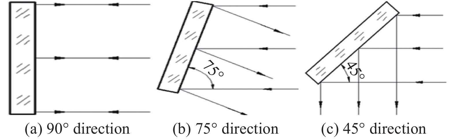
尺寸为1 000 mm×700 mm平面反射镜不使用侧面支撑,仅采用背部支撑方式,在光路中作为折转光线方向使用,为了实现相机可见红外视场的切换,需要驱动反射镜转动一定角度。因此,要求反射镜满足天地不同环境下,位置精度和面型精度的一致性,在地面装调阶段,要求反射镜组件在裸镜检测方位、不同成像方位的精度均能满足光学系统对支撑和卸载的要求。
-
反射镜组件是遥感相机的核心部件,其面型精度和位置精度直接影响光学系统的成像品质。在轨真空、热交变等复杂的环境条件将引起相机结构变化,从而产生的应力传入反射镜使其面型或者位置发生变化,导致成像品质下降。因此要求反射镜组件具有一定刚度满足发射环境的同时,具有一定的应力卸载能力,保证反射镜具有较好的稳定性[7-8]。
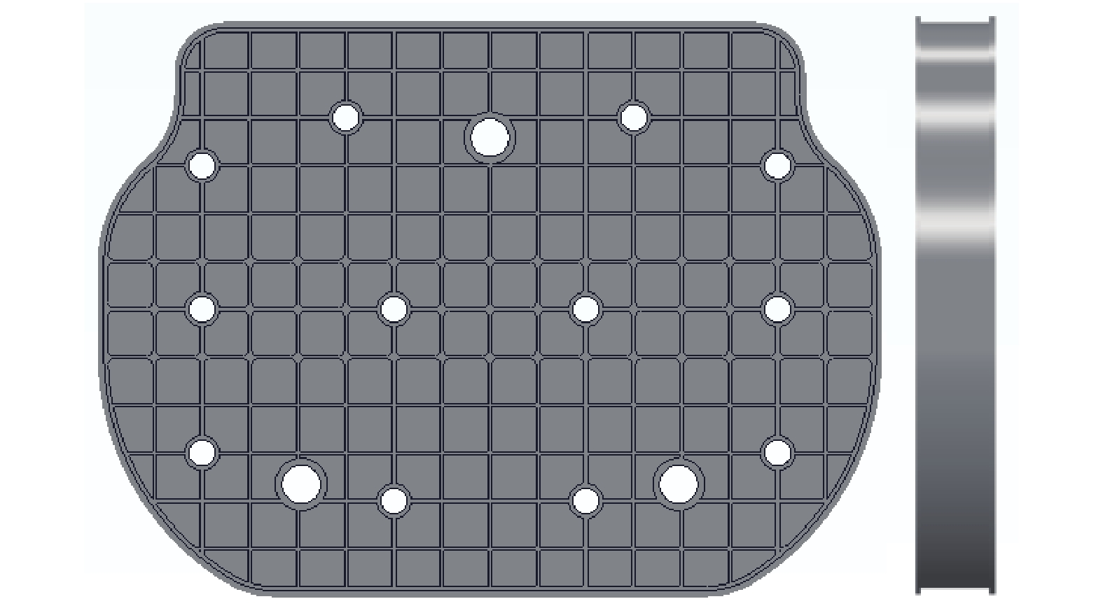
反射镜组件外形:最大外形1 000 mm×700 mm;
反射镜组件质量:小于50 kg;
反射镜组件基频:一阶约束基频不低于80 Hz;
反射镜组件面型:组件在各种载荷综合条件下的最终面型优于0.02 λ(λ=632.8 nm),不同方位时均能满足面型要求,如图1所示;面型主要与裸镜的刚度、支撑结构形式及支撑结构刚度有关。
Figure 1. Different direction requirements of the mirror
反射镜组件抗力学环境要求:在45°方位(同时也是发射方位),30 g静载的情况下,结构强度安全裕度大于0.25;与各个结构件的刚度设计均有关系。
反射镜组件位置要求:在整机成像方位Ⅰ和整机成像方位Ⅱ时,反射镜组件的角位移不超过10″,平动位移不超过0.02 mm;主要与支撑结构的刚度和支撑位置有关。
反射镜组件外形尺寸要求:小于1 120 mm×700 mm×170 mm。
-
由于反射镜组件位于转动机构上,对重量和外包络都有严格的限制,不适宜采用背部和侧面相结合的支撑形式。需要采用另一种形式,半主动光学形式[9],在地面通过对反射镜施加一定数量的重力卸载装置,使面型达到最优,在轨时重力卸载装置切断,重力消失,反射镜只通过三点静定支撑以保证反射镜面型精度,下面从反射镜组件的裸镜设计、静定支撑结构设计、重力卸载结构设计及组件的仿真分析介绍相关技术,反射镜组件模型如图2所示。

Figure 2. Mirror component model(hidden backplane)
-
目前国内外反射镜材料主要有微晶玻璃、ULE和SiC,三种材料的性能参数如表1所示。
ULE 是一种二氧化钛—硅酸盐玻璃,其绝对热膨胀系数在5~35 ℃内极低,因此热稳定性极好。材料焊接性能好,可设计成蜂窝夹层结构,同时ULE 密度小,冷热加工性能良好,材料制备、光学加工和工程应用也相对成熟。从研制经费、研制周期、加工难易程度和线胀系数等方面考虑,选择ULE为反射镜镜坯材料。
在轻量化形式上,有三角形、六边形和四边形的形式,还可以根据支撑位置进行拓扑优化设计[10],针对1 000 mm×700 mm的平面反射镜经过轻量化后重量以及刚度的计算对比,反射镜最终采用四边形单层蜂窝夹芯结构,如图3所示,这样有利于提高反射镜的整体抗弯刚度,三组支撑结构位于反射镜质心面内,反射镜为对称式设计。结合ULE的工艺水平和设计经验,完成了反射镜的详细设计,参数如表2所示,反射镜四边形格子尺寸为d、四边形格板厚度为th、面板厚度为tm、背板厚度为td、支撑孔直径为D,裸镜的重量为30.5 kg。
Material Elastic modulus/GPa Poisson ratio Density103/ kg·m-3 Linear expansion coefficient 10-6/℃ Thermal conductivity /W·m-1·K-1 Zerodur 90.2 0.243 2.53 0±0.05 1.64 ULE 67.6 0.17 2.21 0.015 1.3 SiC 350 0.21 3.21 2.64 146 Table 1. Comparison of mirror material parameters
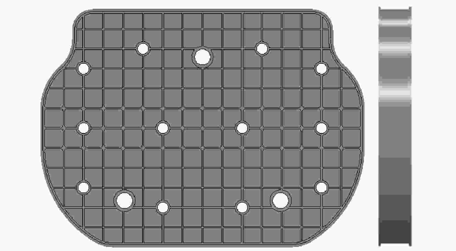
Figure 3. Naked mirror model
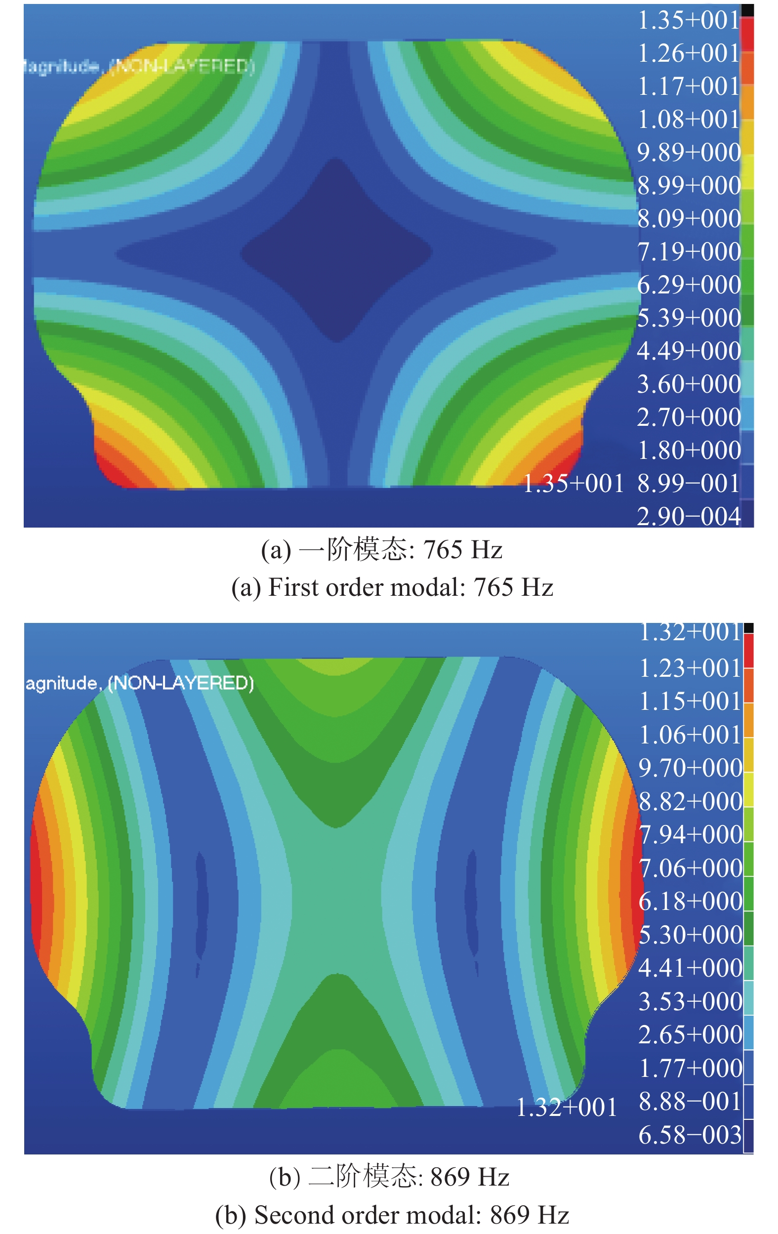
经过分析,反射镜的一阶自由频率达到765 Hz,二阶自由频率达到869 Hz,如图4所示,说明反射镜具有较好的刚度。
Dimension d/mm th/mm tm/mm td/mm D/mm Mass/kg 1 000 mm×700 mm×90 mm 60 4 6 6 40 30.5 Table 2. Structure parameters of mirror

Figure 4. Naked mirror stiffness
-
对于空间反射镜而言,支撑结构设计的重点一是保持反射镜的空间位置精度,二是保证镜面的面型精度。根据反射镜尺寸、形状、指标要求,在支撑形式上采用适合长条形反射镜的多点柔性支撑方案,反射镜柔性卸载支撑的原理需要通过具体的结构设计形式来实现,柔性结构有多种设计形式,如挠性叶片、球铰支撑、柔性铰链、bipod等[11],为了更加合理地使用柔性环节,除了需要积累一定的经验外,必须利用有限元分析手段对其性能分析和评价。
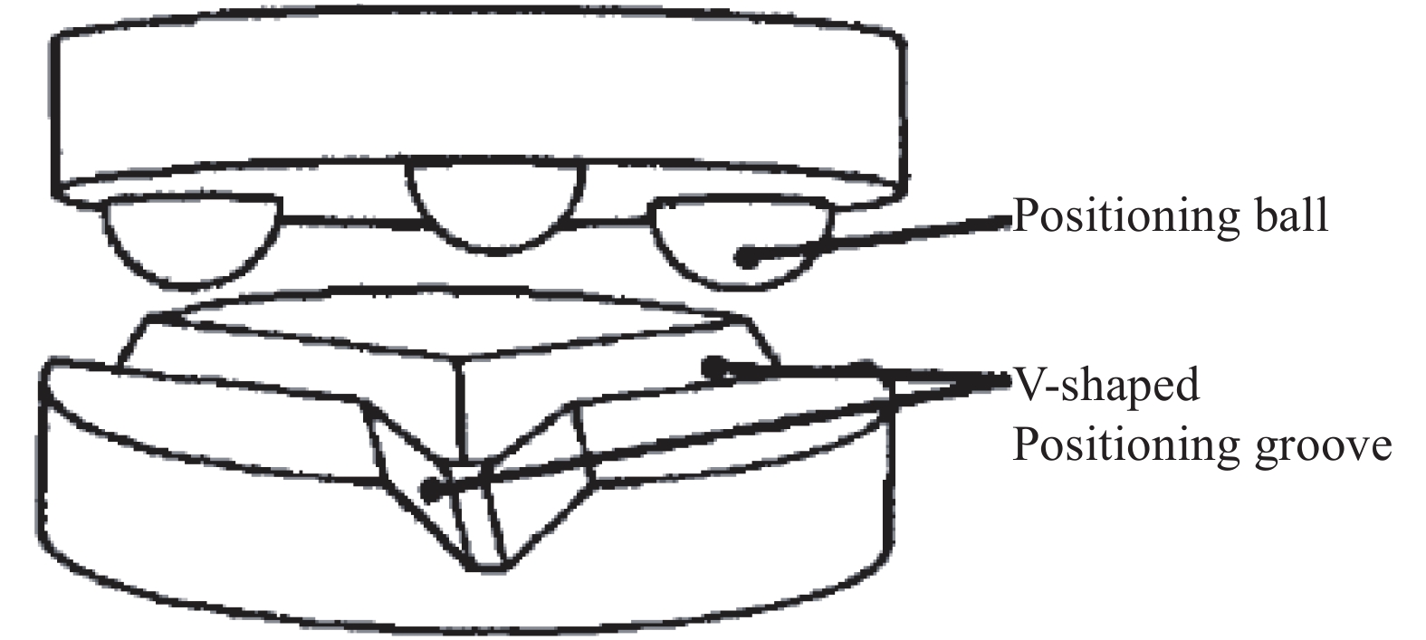
对于多点柔性支撑,核心的问题是自由度解耦,从而实现静定支撑或准静定支撑,反射镜的三点球铰支撑是每个支撑点提供光轴方向和切向两个自由度,三个支撑点正好提供六个自由度(三个轴向支撑约束了轴向移动、径向转动和切向转动;三个切向支撑约束了切向移动、径向移动和轴向转动),没有过约束,实现了自由度解耦,这就是典型的博伊斯运动定位支撑,如图5所示。这种支撑结构正好限制了反射镜所有的刚体运动而没有冗余,支撑结构可以使反射镜和周围环境的弹性变形隔离,从而有效地保护反射镜[12-13]。

Figure 5. Boyce motion positioning support form
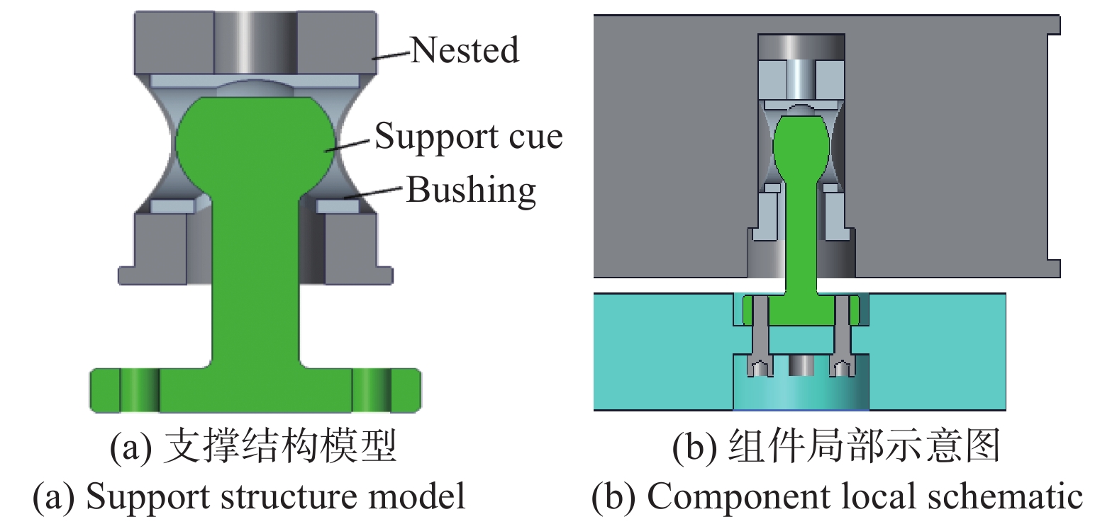
反射镜支撑结构采用三点关节球铰支撑形式,能够减小反射镜受外部应力的影响,从而保证在轨的面型稳定性;每一点的具体支撑结构如图6所示。反射镜嵌套采用与反射镜膨胀系数相匹配的殷钢材料,嵌套通过环氧胶与反射镜粘接,支撑球杆和衬套采用硬度较高的不锈钢材料,反射镜背板采用高比刚度的复合材料制成。
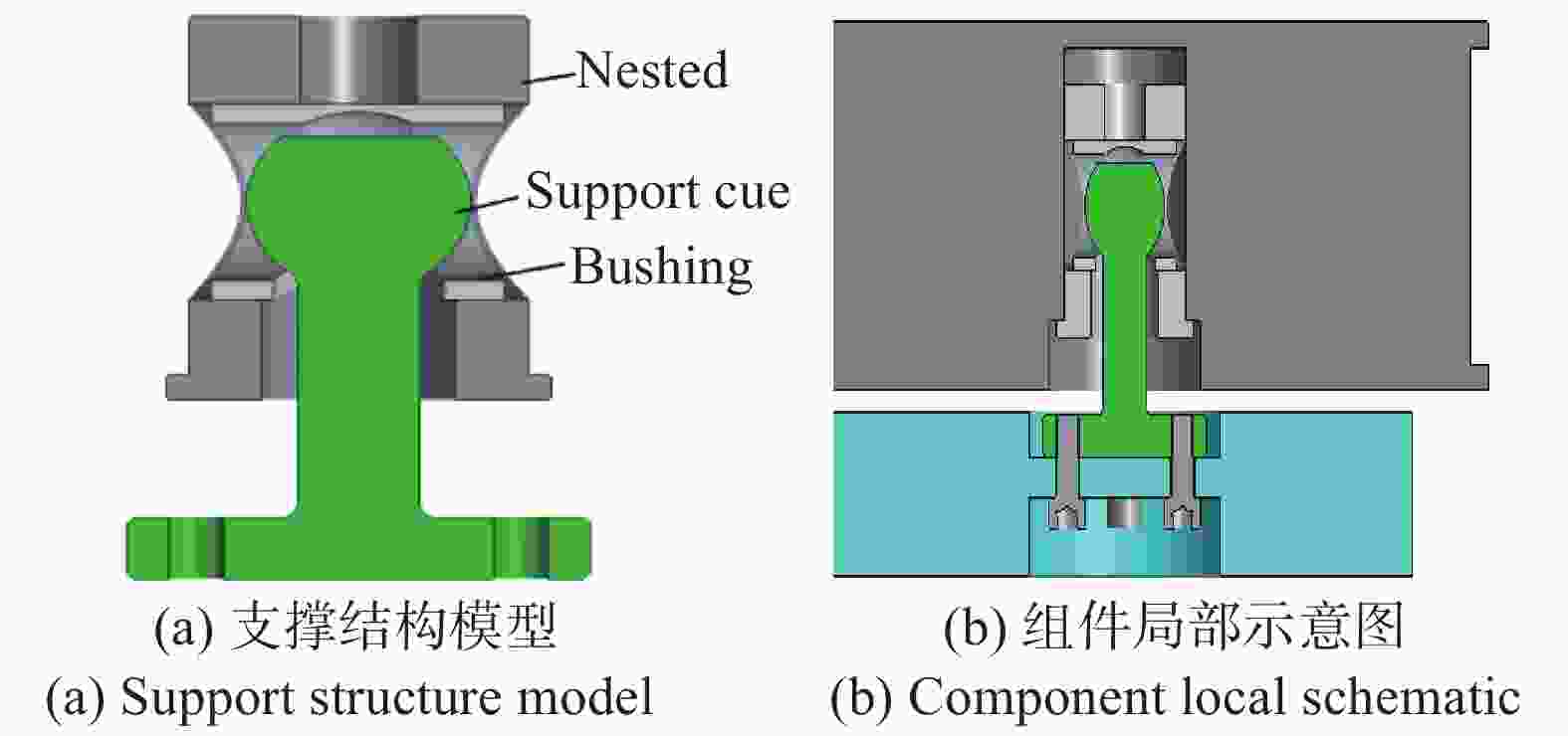
Figure 6. Support structure model of mirror component
-
大口径反射镜在地面装调时,结构受重力影响较大,反射镜的位置精度和面型精度都会发生变化,如果不进行重力卸载,入轨后反射镜支撑结构会发生回弹,造成系统传函下降,从而影响成像质量。李玲等人介绍了大口径同轴相机地面装调时的重力卸载方法[14],采用悬挂重锤的形式,实现了水平装调时前后镜身悬臂的重力卸载;周于鸣等人提出了一种以提供提拉牵引力的方法实现大口径反射镜光轴水平支撑的测试方案[15],两者基本思想都是以砝码形式通过提供向上的牵引力以抵抗物体的重力变形。这种卸载形式需要在反射镜外围有足够的空间进行卸载装置布置,并且在整机测试完成后还能够方便拆除,而本项目中反射镜外围有转动机构和整机主框架的空间限制,因此需要设计一种重量轻且体积小的卸载结构,以满足要求。
针对反射镜自身受力情况而言,受到重力、卸载力以及三组球铰的支撑力共同作用。要求平面反射镜在整机装调测试的两个不同方位,对卸载力方向进行仿真分析,确定最终的卸载力方向为沿镜面法向向上时的反射镜面型是最优的,而不是沿反射镜的重力反向,如图7(a)所示,这主要与三组支撑结构提供的作用力方向有关。裸镜或组件本身在光轴水平测试时,仅靠三组支撑即可实现重力卸载,不需要卸载结构提供卸载力。
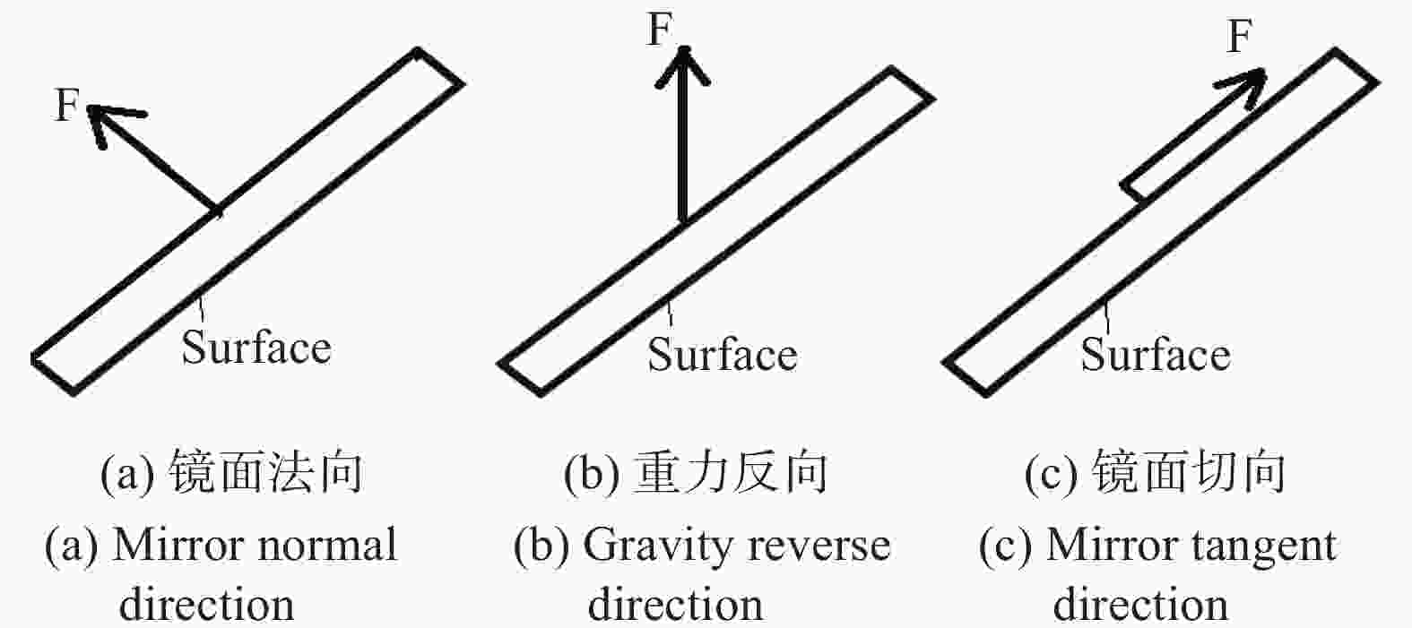
Figure 7. Mirror unloading force direction
根据卸载力方向,设计一种适用于反射镜变方位的卸载结构,通过电机驱动拉伸弹簧,弹簧提供对反射镜拉力,力值的大小通过微型传感器进行检测反馈,如图8所示。
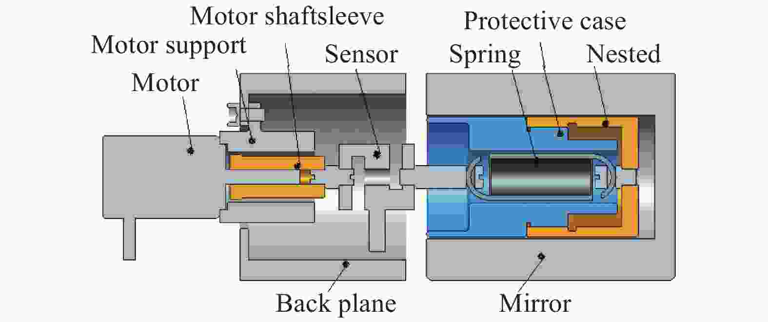
Figure 8. Schematic diagram of mirror unloading structure
卸载结构中的嵌套采用殷钢材料,通过硅橡胶与反射镜进行粘接,保护套采用非金属材料,用于保护拉伸弹簧的运动轨迹,根据弹簧刚度和计算的卸载力大小选择合适刚度的拉伸弹簧,选用微型S型测力计实现弹簧拉力的检测反馈。电机通过支撑座实现与背板的连接,电机驱动电机轴套实现弹簧的平动,其余连接件均采用钛合金材料,每组卸载结构的重量仅为0.19 kg。
这种卸载支撑重量更轻,不占用反射镜的径向空间,卸载力大小可以通过电机驱动随时变化,并且力值大小可实时监测。最终设计完成的反射镜组件重量为47.8 kg(包含12组卸载结构),组件外形尺寸为1 120 mm×700 mm×162 mm,满足设计要求。
-
利用有限元分析方法和数值技术手段,对反射镜组件在轨重力释放、温度变化及装配应力情况下的稳定性进行了分析,采用有限元分析软件Patran/Nastran建模和后处理,面型提取采用Metropro软件。重力分析是在组件X向和Y向施加1 g静过载,温度分析是约束反射镜背板安装面,组件在20 ℃的基础上均匀温升2 ℃,强迫位移是在反射镜背板的安装面上施加0.005 mm的位移量,并对几种载荷共同作用下的影响进行了分析,结果如表3所示。
Result Gx Gy △t △5 μm Gx+△t+
△5 μmRMS/λ 0.006 0.004 0.002 0.001 0.007 Displacement/μm 13 15 5 5.85 15 △θ/(″) 2.2 3 0.3 0.64 2.4 Table 3. Simulation analysis results of the component
反射镜组件采用三点球铰支撑方案,具有足够的强度和可靠的连接刚度。反射镜裸镜的加工面型精度为1/60λ,反射镜在光轴水平时自重作用下RMS值为6/1 000λ,镜面最大位移为13 μm;自重、温度和强迫位移载荷共同作用下,RMS值为7/1 000λ,镜面最大位移为15 μm,仿真分析结果验证了这种三点球铰支撑具有良好的卸载作用,能够满足反射镜在空间环境中面型的稳定要求。
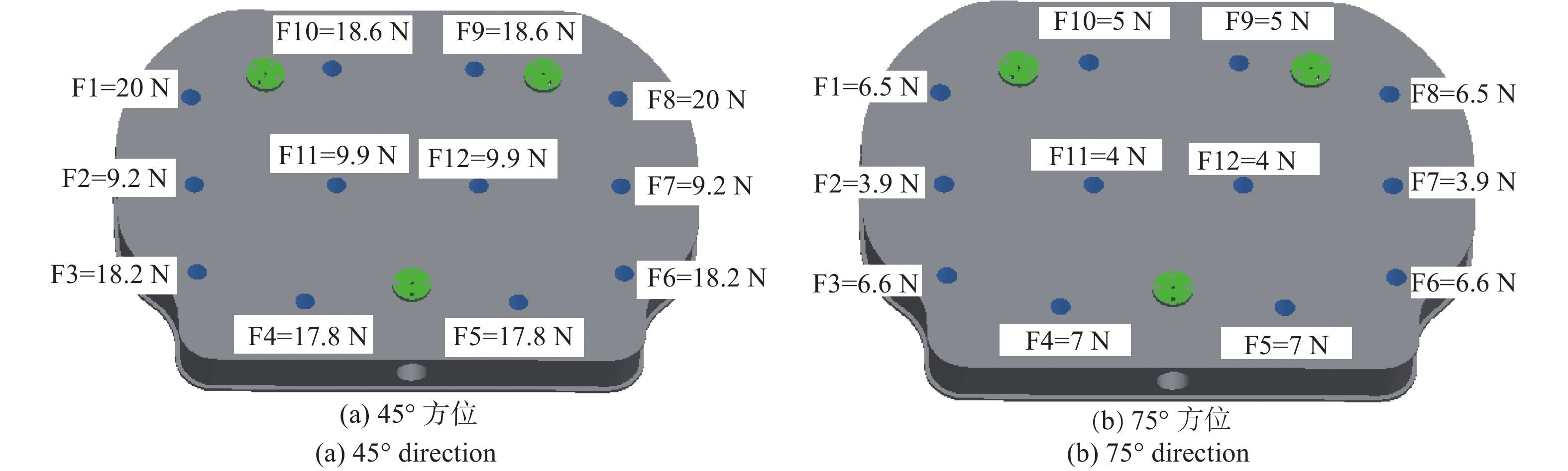
在地面装调阶段,需要对反射镜进行重力卸载,对卸载力的数量、位置、力值进行优化。在尽可能少的卸载数量的前提下,以面型误差RMS最小为优化目标。不同方位卸载力的优化结果见图9,面型云图见图10。

Figure 9. Optimization results of unloading force in different directions
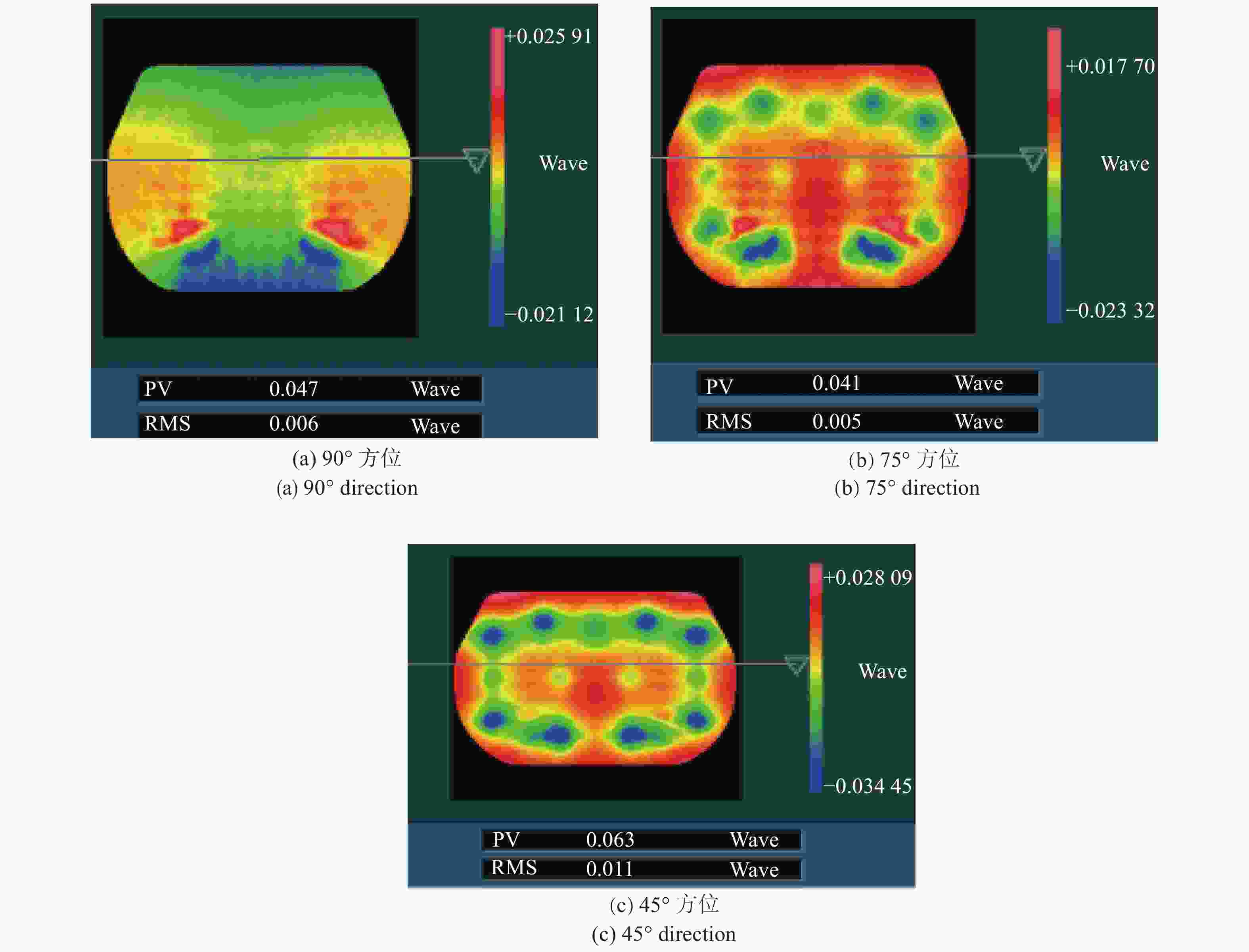
Figure 10. Optimization results of RMS in different directions
在45°方位时,反射镜RMS面型为0.011λ,反射镜镜面的最大位移为15.1 μm,镜面最大偏转为8″。在发射状态下30 g过载,反射镜的最大应力为7.14 MPa,结构件的最大应力为120.9 MPa,远小于材料的许用应力,满足结构强度安全裕度均大于0.25的要求。在75°方位时,反射镜RMS面型为0.005λ,反射镜镜面的最大位移为14.2 μm,镜面最大偏转为7.8″,满足对反射镜的位置精度要求。
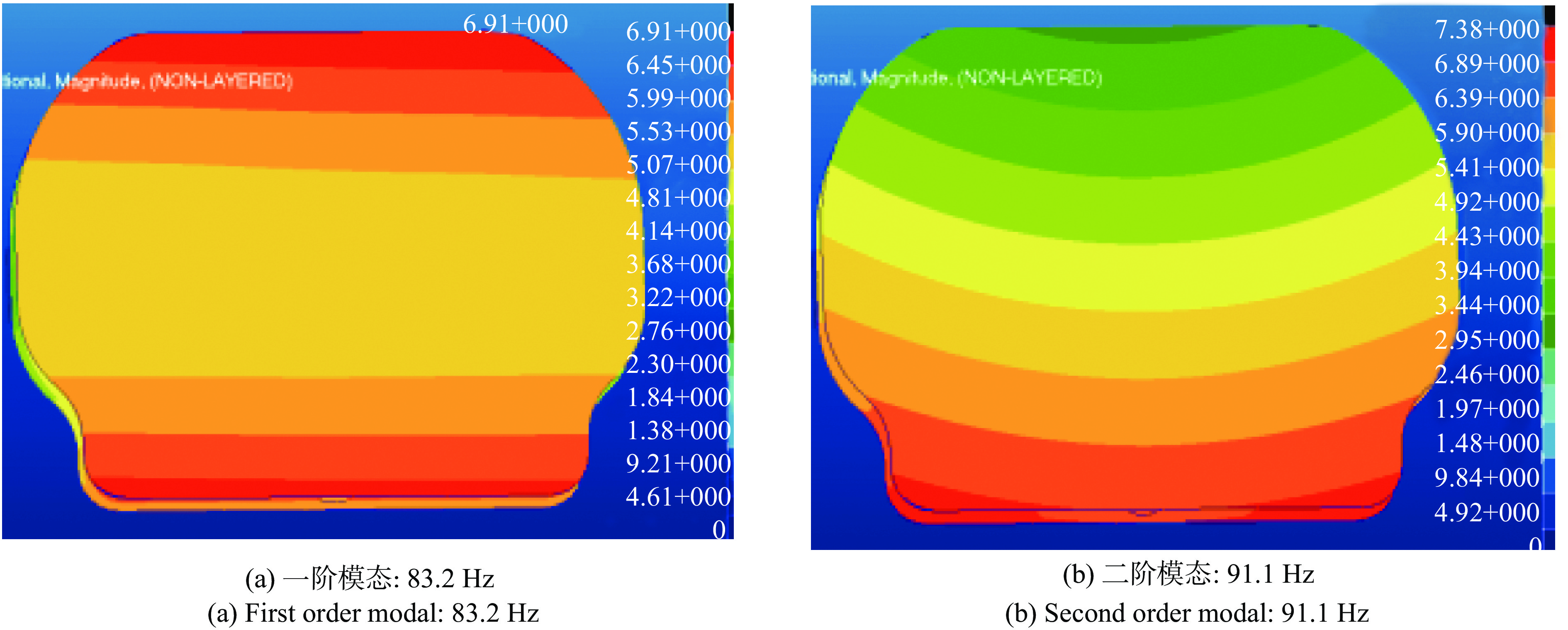
另外,根据组件约束模态仿真结果显示,反射镜组件的基频为83.2 Hz,振型为短轴方向的平动,如图11所示,说明组件具有较高的设计刚度,能够满足发射段力学环境要求。

Figure 11. Modal result of the mirror component
-
从新型可见红外相机一体设计的需求出发,介绍了一种新的大口径变方位反射镜组件的设计方法,为了减少体积和重量,采用柔性支撑设计加地面重力卸载的方式。反射镜裸镜的基频达到765 Hz,具有一定的刚度;在支撑形式上采用的是博伊斯运动定位支撑形式,组件在轨均匀温升时,面形变化仅为0.002λ,并能保证良好的位置精度;在地面重力卸载设计上,采用的是电机驱动的形式,这种形式的结构重量轻,体积小,卸载力可设计;组件的最终重量为47.8 kg。最后对反射镜进行了力热分析和卸载力优化,仿真数据表明大口径变方位反射镜组件具有良好的应力卸载能力,地面装调状态,通过卸载完全可以满足位置和面型精度要求;组件一阶频率为83.2 Hz,能够满足发射段力学环境要求。这种对大口径变方位反射镜的设计方法可以为同类反射镜的设计提供参考。
Design of large-aperture variable-direction mirror for space remote sensing camera
doi: 10.3788/IRLA20200008
- Received Date: 2020-04-01
- Rev Recd Date: 2020-05-20
- Available Online: 2020-07-23
- Publish Date: 2020-07-23
-
Key words:
- variable-direction mirror /
- large-aperture /
- flexible support /
- gravity unloading
Abstract: With the development of remote sensing technology, new camera requires large aperture variable-direction mirrors with higher accuracy. A new type of back support structure with highly stable support design was proposed for 1 000 mm×700 mm large-aperture variable-direction mirror. Compared with the conventional design, it had the characteristics of small volume envelope, light weight and wide adaptability. The mirror was made of ULE, and the light weight form of honeycomb layer was used. The mirror was mounted by means of a 3-point ball joint flexures system on the back. The stress in reflector assembling and the influence of thermal stress on the orbit was eliminated. It reached the stress-free support of the mirror. The problem of consistency between the ground test and in orbit was solved through the design of gravity unloading structure and the optimization of the unloading force. The simulation analysis shows that the surface RMS is 0.006λ(λ=632.8 nm) at 90° mirror testing direction. The surface RMS is 0.005λ at 75° camera imaging testing direction Ⅰ. The surface RMS is 0.011λ at 45° camera imaging testing direction Ⅱ. The first order modal of the component is 83.2 Hz, which has a high design stiffness and can meet the requirements of the mechanical environment during launch. This large-aperture variable-direction mirror design can meet the needs of new types of remote sensor and can provide a reference for the design of similar mirrors.


 DownLoad: