


-
透射元件在高功率激光系统中有着广泛的应用,是光学系统中必不可少的基本元件,而随着激光器输出能量的不断提高,其激光诱导破坏问题已经成为激光损伤研究领域的重要议题之一。纳秒脉冲激光对透射元件的破坏机理主要是热力效应[1]。对于热力损伤机理和热力破坏作用,许多研究都进行了分析和讨论,包括从材料吸收[2-3]、禁带宽度[4]、电场调制[5]、光谱性能[6]、缺陷引入[7-8]、激光参数[9]、辐照条件等角度阐述了纳秒脉冲激光的损伤诱因和机理。近年来,利用泵浦探测成像技术,Demos[10-11]等人系统地研究了熔融石英材料表面的损伤过程和各种伴随产生的现象,使纳秒激光损伤的动力学过程更加直观地呈现了出来,显著推动了研究人员对损伤瞬态特征和发展演化的理解。
透射元件发生损伤后会向周围喷发粒子,粒子的动能、喷射角度、空间分布以及尺寸形貌[12-14]等信息不仅对激光损伤动力学研究非常重要,同样影响着强激光装置中其他光学元件的使用性能,如喷射粒子附着在后续元件上成为污染物,进而降低元件的激光损伤阈值和使用寿命[15]。不同厚度以及不同材质的金属膜层损伤机理和粒子喷发也会存在明显差异。然而,同样可以利用喷射粒子成为主动注入源,如在托卡马克装置中,通过激光吹气系统向等离子体中输送特定杂质[16],通过杂质在等离子体中产生的瞬态扰动和光谱信息变化,可以研究杂质在等离子体中的输运行为。因此,了解喷射粒子的喷射状态,对于强激光装置运行、激光吹气系统优化和等离子体状态监测有着重要意义。
文中主要针对纳秒脉冲激光诱导透射元件和金属膜层喷射粒子的时域过程、空间分布和角度特征,以及激光能量、真空度等参数的影响等进行了研究。
-
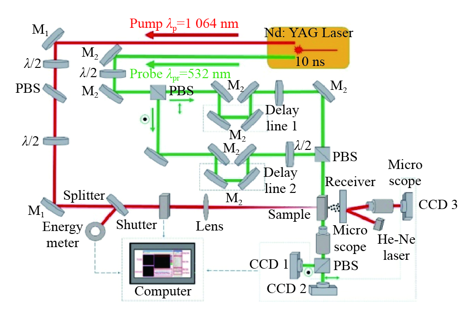
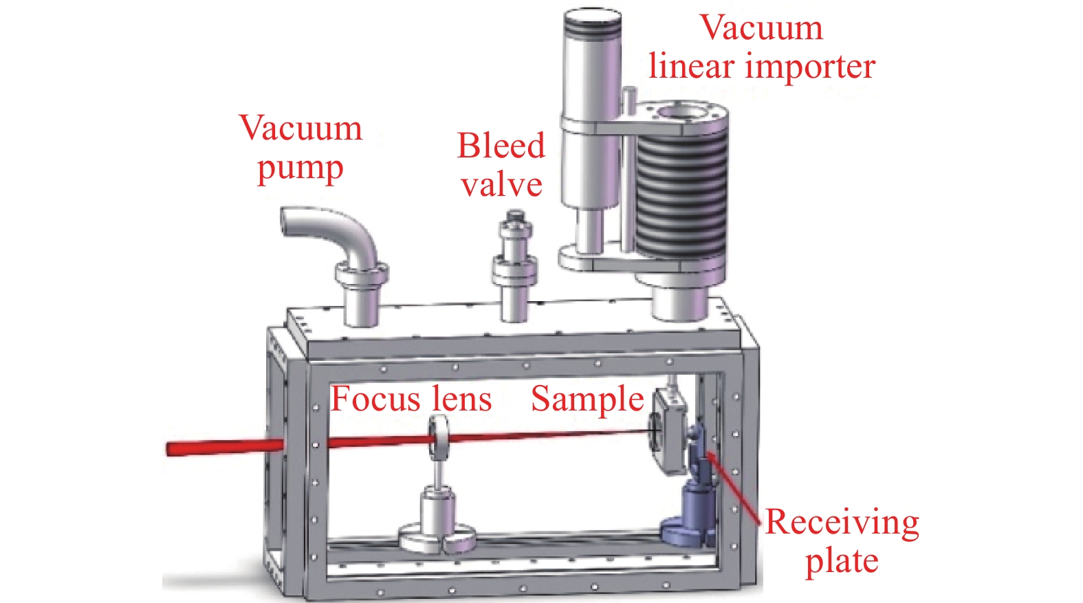
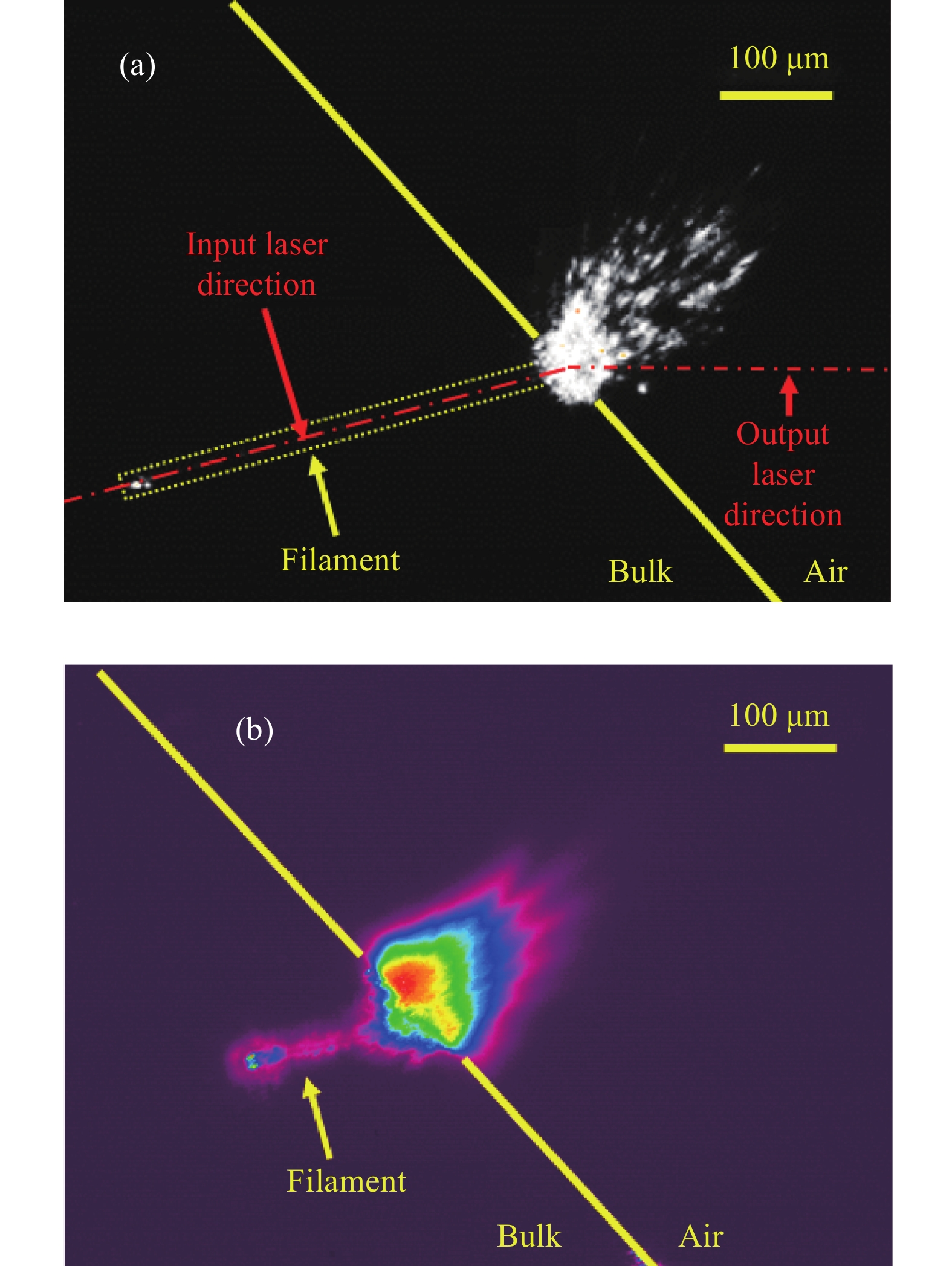
实验使用的是光谱物理Nd:YAG激光器,可以同时输出波长为1064 nm和532 nm的两束激光。其中,1064 nm波长激光的脉宽为10 ns,532 nm波长激光的脉宽为8.5 ns,以这两束光分别作为泵浦光和探测光建立泵浦探测成像系统,如图1所示。1064 nm的泵浦激光通过一系列激光参数诊断单元后直接辐照至待测样品出射面,诱导透射元件后表面发生损伤破坏。在焦点处的光束直径(1/e2)约为153.9 μm,透射元件为熔融石英样品(100 mm×50 mm×10 mm)。采用配备70–700×目镜的HIROX长距显微镜和两个Spiricon SP620U的CCD来获得微米尺度成像分辨率的图像。同时,通过调节延时光路控制探测激光在特定的延迟时间内对测试区域进行辐照,实时诊断测试样品的损伤信息。探测光通过偏振分光棱镜分成偏振方向相互垂直的两束光,使得同一过程可以同时得到两幅图像。
Figure 1. Schematic of experimental light path
此外,在样品出射面后的一定距离处设置粒子接收板来收集喷射粒子。对于接收板上亚微米和微米尺寸粒子的测量和统计,利用高倍显微镜对准单一视场、调焦清晰,然后采用光栅轨迹扫描大面积范围,移动过程中同步触发相机拍照;通过软件对激光辐照前后图像的对比,识别喷出粒子,获得尺寸和位置等信息。其中单一视场尺寸为0.235 mm×0.176 mm、显微镜分辨率约为0.36 µm。对于接收板上原子级元素的产生,由激光诱导透射元件上金属薄膜的喷发获得,采用能谱仪对接收板上的原子或元素分布进行统计分析。
-
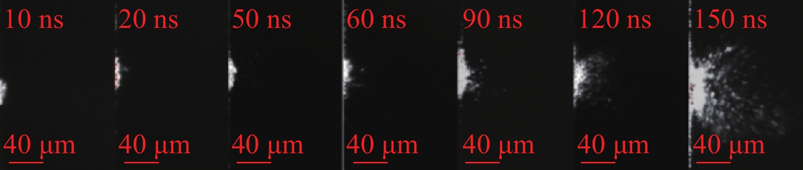
利用暗场条件下的泵浦探测成像技术,笔者所在课题组研究了激光损伤发生后在不同时间阶段的粒子喷射行为。如图2所示,是在完全相同参数下进行大量实验后获得的典型的图像。自左至右为泵浦激光辐照10 ns至150 ns后,由探测激光获得的瞬态图像,包含了不同时间延迟下粒子喷射初始并逐步发展的过程,以及在更长的时间尺度出现显著喷射现象。由此可知,激光损伤发生的前20 ns,并未发现明显的喷射粒子,主要原因是初始破坏时热力作用明显,将首先产生显著的材料蒸发和体材料破裂;随后在30~90 ns范围,随着体材料和团簇区喷出,喷射粒子因为速度的差异化而逐渐分离;在120~150 ns范围,喷射粒子特征非常明显,且这一过程将进一步持续,直至毫秒甚至更长时间尺度。

Figure 2. Transient images of particle ejection on the exit surface at delay time from 10 ns to 150 ns
-
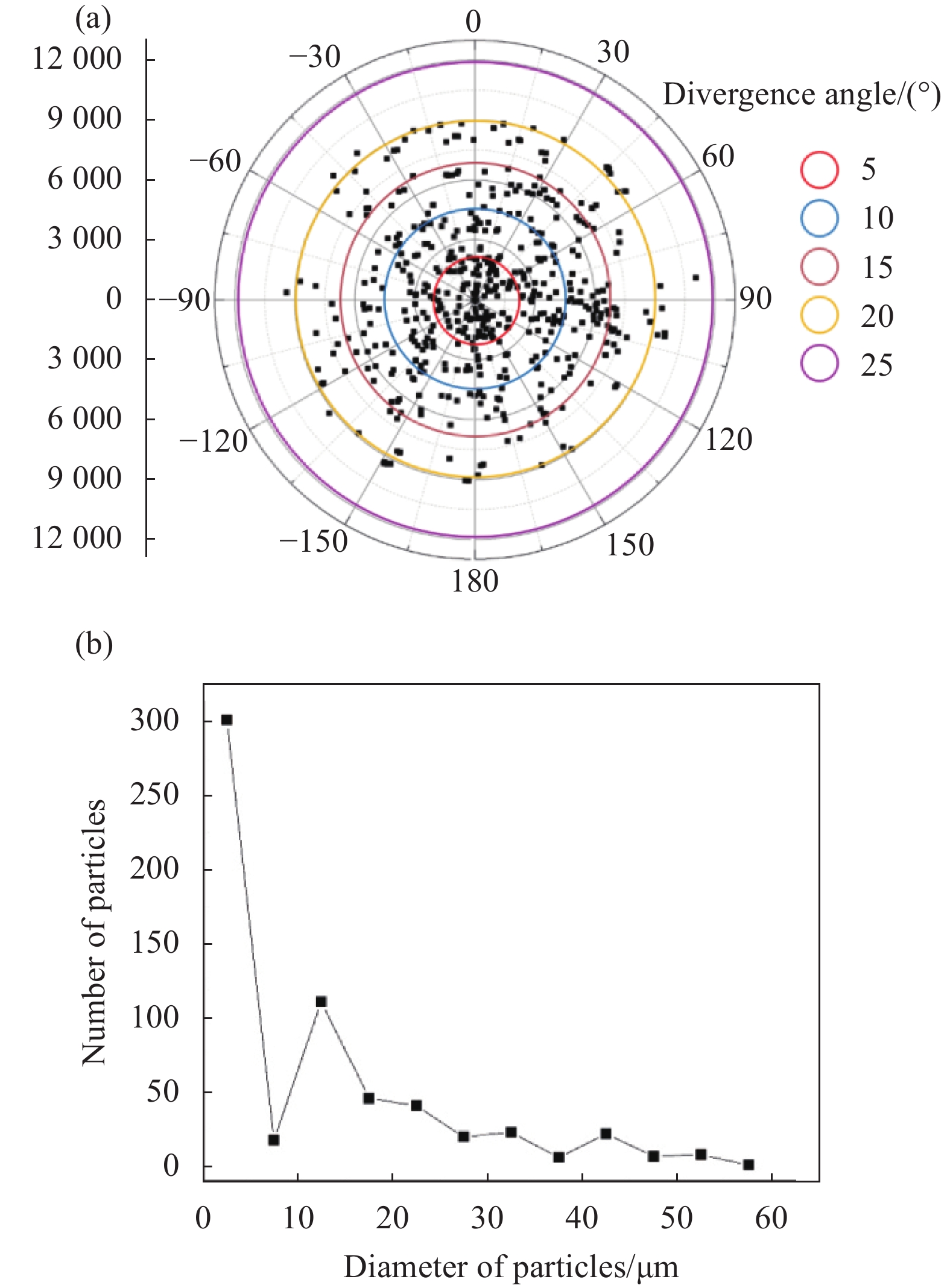
在透射元件后面的不同位置放置粒子接收板,结合接收板上粒子的位置、与透射元件出射面的距离,可以计算出粒子的空间分布和喷射角度。近似认为粒子的喷射轨迹是以损伤破坏中心点为顶点的轴对称圆锥,根据公式(1)可以得出粒子接收板上每一个粒子的角度分布,其中d为粒子接收板到样品损伤点的垂直距离,即圆锥的高,d’为圆锥的底面半径,θ即为发散角。
相同出射角度的粒子拥有类似的性质(因为每一个粒子质量极小,忽略重力因素的影响)。粒子的分布呈现对称圆形,且随着粒子接收板距离的不同,圆所覆盖的直径不同;粒子接收板离出射面越近,圆越小;粒子接收板离出射面越远,圆越大(粒子接收板最远距离为40 mm,当距离大于40 mm时,部分粒子已经无法飞跃到这个距离)。而比较不同损伤尺寸时,发现粒子分布的规律不随损伤凹坑尺寸的变化而变化,依旧呈现近似圆形分布。激光能量密度为300 J/cm2,接收板距离为25 mm,粒子分布示意图如图3(a)所示,大部分粒子主要集中在20°发散角内。

Figure 3. Angular (a) and size (b) distribution of particles on the receiving plate
图3(b)是粒子大小与喷射粒子个数之间的分布关系图。随着粒子尺寸的增大,粒子个数不断减小。大部分粒子主要集中在20 μm以内,存在极少数尺寸大于50 μm的粒子。
-
图4为接收板设置于25 mm距离处,改变激光能量所得到的接收板上粒子分布情况。横坐标为距中心点之间的距离,每个数据点表示该点与前一个点之间的环形区域内的粒子个数。可以看到,随着能量的提高,接收到的粒子数更多,更多的粒子集中在距离中心9~10 mm的区域内,发散角大约20~22°范围内。

Figure 4. Distribution of particles on the receiving plate at 25mm irradiated by different laser energies
图5是通过调节激光焦点位置,改变透射元件初始损伤的深度位置对接收板上的粒子分布的影响。图5(a)为正常的表层损伤,即激光焦点在元件与空气界面附近或在空气侧;图5(b)为深层损伤,将透镜的焦点前移至材料内部约30~50 μm位置,因焦深影响和损伤的不确定性,实际损伤的位置很可能在20~100 μm深度范围或更深。初始损伤发生在不同深度,其扩展过程和粒子出射特征存在差异。
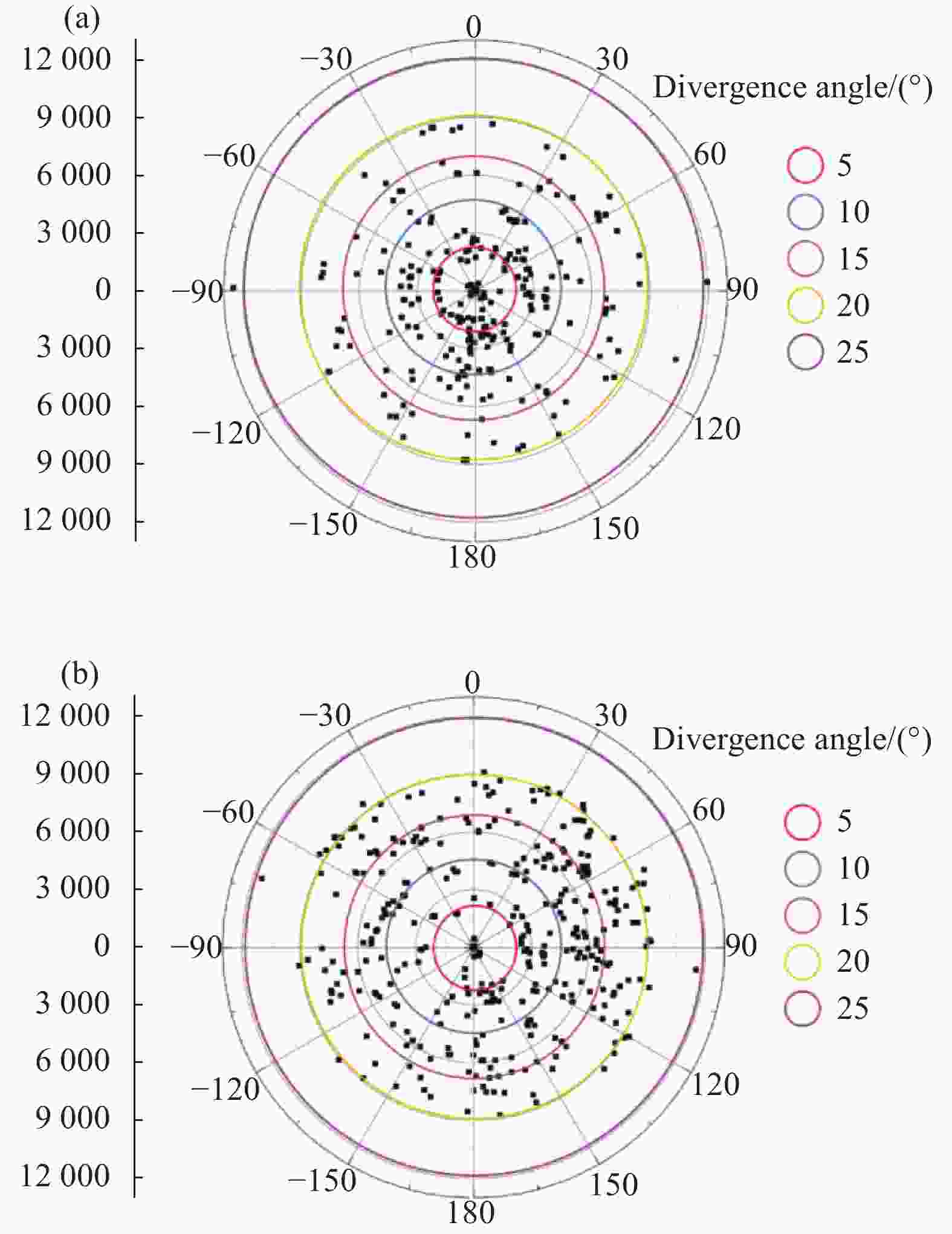
Figure 5. Particle distribution when initial damage occurs (a) at the surface (338 particles) and (b) inside the material (424 particles)
对于正常的表层损伤,粒子喷射以前向为主,喷射方向相对集中,粒子分布在中心相对较多,整体在15°范围内;对于深层损伤,喷射方向相对发散,存在特定喷射方向,粒子分布在中心相对较少,但整体在20°内。
-
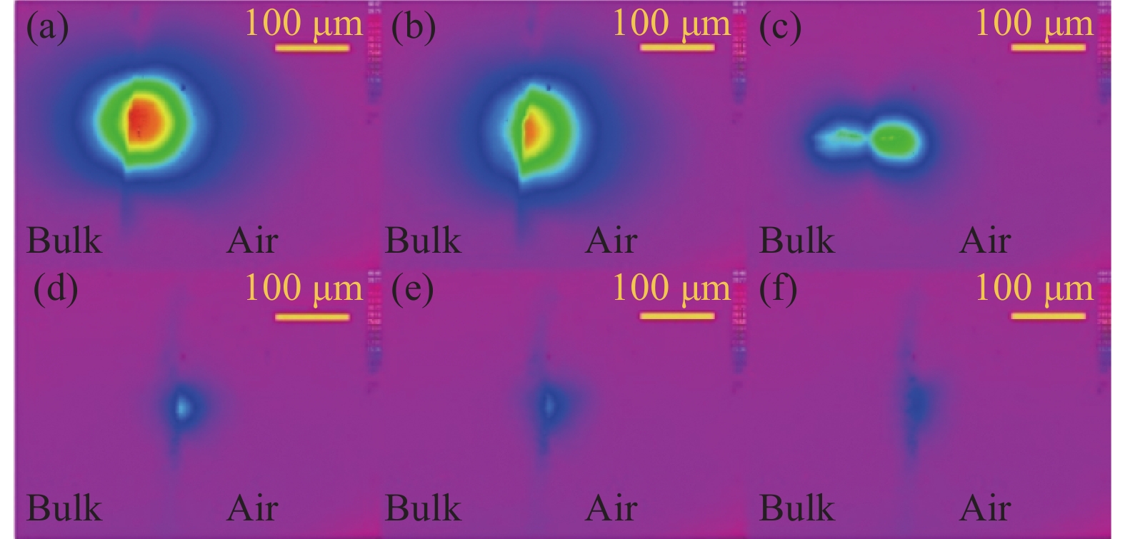
图6为简易真空装置,结合机械泵可以实现低于百帕大气压强的真空环境模拟。如图7所示,1064 nm波长泵浦激光作用于透射元件出射面处会产生等离子体,等离子的强度会随真空度的改变而变化,其中图7(a)为正常大气压强。可以看到,喷发的等离子体分布于透射元件内外两侧,能量主要集中于空气一侧,随着真空度增加、大气气压降低,等离子体强度明显减弱。

Figure 6. Vacuum device

Figure 7. Images of plasma eruption with increasing vacuum (lateral view)
图8给出了真空和大气环境下接收板上粒子的尺寸分布和喷射角度特征对比,能量密度300 J/cm2,接收板放置在透射元件出射面后方25 mm处。相比大气环境,在真空环境下接收板上收集到的喷射粒子数更多一些,而发散角分布基本一致,均在约20°以内。主要原因之一可能是,随着真空度降低,等离子体减弱,因此在喷射初期喷射粒子受到等离子体的影响减小。但是由于接收距离相对较短,且粒子的尺寸和分布主要由粒子喷射的初始状态决定,包括热力作用过程中冲击波和等离子体对材料的冲击、撕裂和蒸发等物理作用,喷射粒子具有的初始动能在喷射初期已获得,因此即使在真空环境下,喷射粒子的角度与尺寸分布并未有明显差异。

Figure 8. Angular distribution (a) and size distribution (b) of particles on the receiving plate in vacuum and atmospheric environment
-
前面讨论的都是正入射、输出面的透射元件损伤,除此之外,课题组还研究了45°入射时粒子的喷射特征。入射激光在材料内部因折射率的差异并不是正好45°入射到输出面,但会在SiO2-空气界面折射后以45°出射。图9(a)为出现丝状损伤时的粒子喷射图像。丝状的方向与激光入射方向一致,是表面损伤后形成的等离子体沿激光入射方向拓展而成。图9(b)给出了类似条件下的等离子体喷发图像。尽管等离子分布是长时间的积分强度,但其形貌和粒子喷发特征类似丝状沿线都残留了等离子体痕迹,在空气中等离子体分布同样沿法线对称,且出现多个小峰值,这与强烈的粒子喷射特征相对应,但等离子体强度由中心向周围衰减,而粒子喷射由中心向空间中发散。
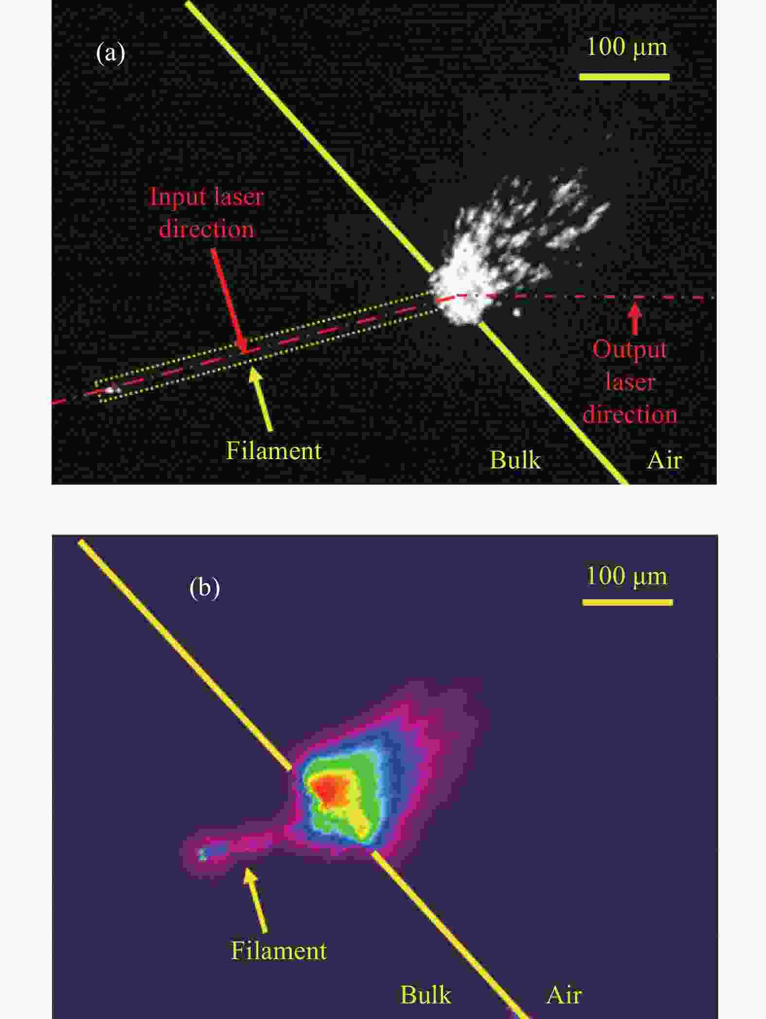
Figure 9. Spray characteristics on the output surface at 45° incident. (a) Transient image of particle ejection at 150 ns; (b) Image of plasma eruption
-
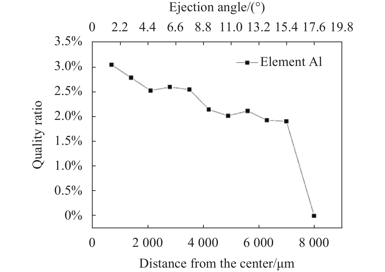
采用电子束蒸发的方法在熔融石英基板上镀制1 µm厚的金属Al膜,由1064 nm波长激光诱导金属Al膜损伤并喷发,能量密度33 J/cm2,在距离出射面25 mm处设置接收板,收集喷出的金属元素,然后采用能谱仪对接收板上的原子或元素分布进行统计分析。
能谱仪的测量过程为:近似认为接收板上元素分布区域为圆形,从圆心开始,沿某一半径方向,每次固定移动0.5~1 mm的距离,选取相同面积的区域,对区域内的元素占比进行测试,直到结果不再出现该金属元素为止。图10为接收板上收集到的Al元素的空间分布和角度分布,在接收板上Al的分布范围基本分布在半径为10 mm的圆形区域内,喷射角度在20°范围内,元素占比沿着半径方向逐渐下降。

Figure 10. Spatial and angular distribution of Al elements on the receiving plate
-
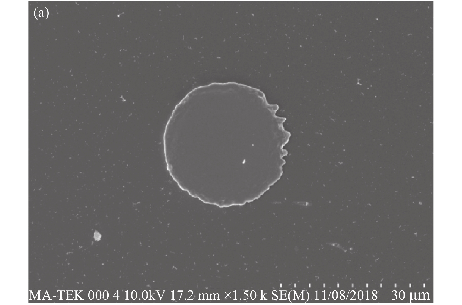
金属薄膜的厚度和膜层结构也会对热力损伤过程产生影响,为此对比了由电子束蒸发方法镀制的1 µm厚的Al膜和由磁控溅射方法镀制5 µm厚的Al膜。图11为真空环境下不同厚度Al膜在接收板上的元素分布特征,其中能量密度33 J/cm2,接收板距离出射面25 mm。可以发现,在相同激光能量下诱导的1 µm和5 µm Al膜所喷发出的原子分布非常接近。主要原因是激光光斑尺寸和激光能量固定,此时产生的金属膜层破坏尺寸类似;膜层薄的情况下更容易彻底蒸发喷出,膜层厚容易导致不完全蒸发并伴随块状碎片喷射;此外,磁控溅射镀制的膜层内应力大、膜层致密度高,容易出现不规则破坏形貌和碎片状剥落,造成许多颗粒状粒子和碎片的非均匀喷射,降低接收板的接收效率。

Figure 11. Distribution of Al on the receiving plate in vacuum environment with different thickness of Al films
-
相比Al膜,Ti膜的熔点高(Al的熔点为660 °C、Ti的熔点为1668 °C),且不易燃烧,当膜层发生损伤时无法被彻底蒸发成原子态,存在明显的熔融状微粒形态、且均匀分布、数目多。特别是在真空条件下,熔融的Ti金属液滴难以在飞行过程中冷却,仍旧会以熔融态为基本形态,直至接触到粒子接收板后冷凝,所以在接收板上呈现为圆形凝固态的形貌,如图12(b)所示。相比之下,Al膜的残片较多为蒸发不完全、由热力破坏作用剥离的不规则碎片,如图12(a)所示。


Figure 12. Typical Al(a) and Ti(b) fragments on the receiving plate in vacuum environment
-
文中首先利于激光损伤阈值测量系统和泵浦探测成像系统,获得了激光诱导透射元件喷射粒子在初期阶段的瞬态图像,了解和掌握了粒子喷射行为的时域演化过程。然后,通过在样品后方放置一个接收板,收集喷射出的粒子并统计分析,得到了不同参数和作用条件下的粒子尺寸、数量以及喷射角度范围。同时,利用简易真空装置,研究了真空环境对喷射粒子的影响。
最后,研究了激光诱导金属膜喷发的空间和角度分布,金属膜的喷发与不同金属的热学参数和膜层性质密切相关,喷射出的粒子大多以尺寸极小的原子态的形式存在,通过能谱仪统计分析接收板上的元素分布信息,获得了蒸发态原子的喷射分布特征。上述实验为透射元件和金属膜层在纳秒脉冲激光诱导下喷射的微米尺寸粒子和蒸发态原子的空间分布、角度分布等特征研究提供了实验数据支撑。
Distribution characteristic of ejected particles from transmissive element induced by nanosecond laser
doi: 10.3788/IRLA20200065
- Received Date: 2020-05-07
- Rev Recd Date: 2020-06-10
- Publish Date: 2020-11-25
-
Key words:
- particle ejection /
- transmissive element /
- nanosecond pulsed laser /
- pump-probe detection imaging techonlogy
Abstract: Optical instrument will be damaged when irradiated by high-energy laser. The damage process is accompanied by material fracture, structural collapse and particle ejecting, and the particles emitted will affect the performance of surrounding optical instruments. In this paper, a dual-beam pump-probe imaging system was built to obtain a transient image of the particles ejected form transmissive element induced by nanosecond laser. A particle receiving plate was placed behind the sample, so that the spatial distribution of the particles as well as the size and angular characteristics were analyzed. Then, the effects of different laser energies, different particle receiving distances and vacuum environment on the particle distribution were studied. In addition, combined with EDS spectrum detection technique, the characteristic of particles induced in the metal film was investigated. Also, the differences between different kinds of metal film and the influence of the vacuum environment were studied. The results show that the transmissive substrate emits micron-sized particles under laser induction, while atomic state particles or molten droplets from metal film. The distribution characteristics of the particles on the final receiving plate are mainly affected by the initial conditions. There is little change in the vacuum within a few pascals, and different metal films are also significantly affected by their own properties.....


 DownLoad: