


-
辐射源分为有效辐射与杂散辐射两部分,从光源直接到达探测器光敏面的辐射为有效辐射,如图1所示。

Figure 1. Effective radiation
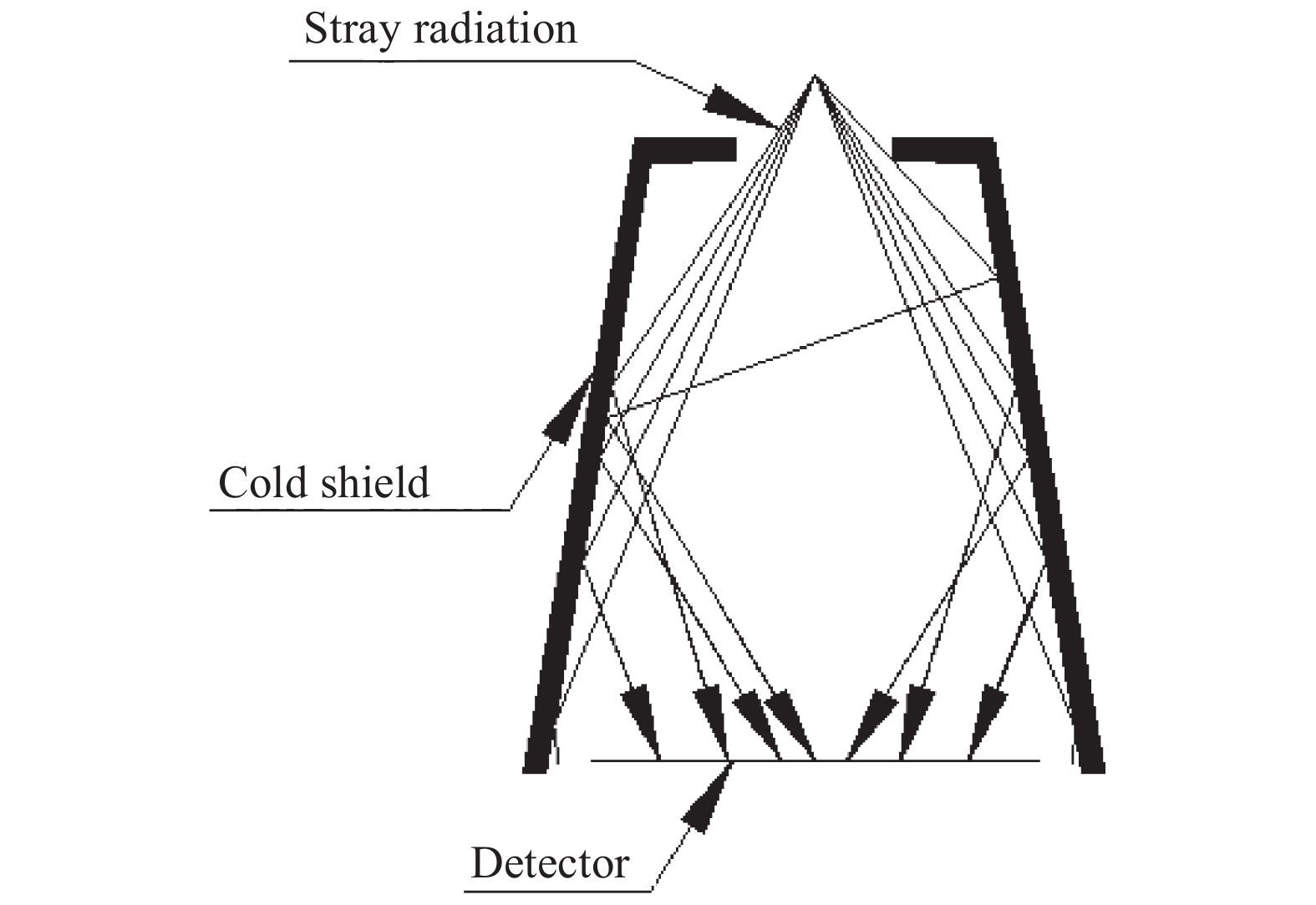
其余经过折射、反射或者散射到达探测器光敏面的辐射为杂散辐射,如图2所示。

Figure 2. Stray radiation
-
冷屏不添加挡光环时,随着冷屏高度增加,增高的部分会增大到达光敏面的杂散辐射能量,反而导致冷屏杂散辐射抑制能力降低,如图3所示,因此有必要通过添加挡光环来抑制杂散辐射,提高冷屏效率。根据光路传播规律,结合仿真分析设计出的挡光环结构可以有效抑制杂散辐射,起到提高冷屏效率的作用。

Figure 3. Increase the cold shield height
-
红外系统应用于匹配制冷型探测器时必须要考虑出瞳与红外探测器冷屏的匹配方式。文中在红外光学系统出瞳与冷屏完全匹配的前提下,从冷屏高度和冷屏外壳两方面对冷屏效率进行讨论。
冷屏效率的讨论采用试验与仿真相结合的方式,试验中以探测器非均匀性测试结果作为对比参数,仿真分析中以杂散辐射能量和有效辐射能量的变化幅度、分布情况的综合结果作为对比参数。
-
采用视场角的计算方法,参照公式(1)[6]以640×512探测器为例,F数不变时,对冷屏内表面经过黑化处理后,对不同高度的冷屏结构进行非均匀性计算(如图4所示):

Figure 4. Schematic diagram of pixel FOV
冷屏高度分别为23、25、29 mm,芯片尺寸为19 mm×16 mm,对应的探测器非均匀性理论值分别为7.85%、6.72%和5.09%。冷屏高度越高,非均匀性越小。根据以上计算数据,采用相同探测器组件、相同芯片进行对比测试。
测试数据见表1。
No.1 No.2 No.3 Cold shield height/mm 25 29 23 Non-uniformity 5.46% 6.11% 6.95% Table 1. Test data
表1中冷屏高度增高,探测器组件的非均匀性没有变小,有的反而变大,2号冷屏比1号冷屏高4 mm,非均匀性反而升高0.65%。测试数据与理论计算不一致,就此问题需对冷屏高度与冷屏效率的关系进一步仿真,查找原因。仿真分析前,对比试验用冷屏结构发现:1号和3号冷屏添加了挡光环,挡光环是按照光路传播路径进行设计的,各自添加了三片挡光环来有效抑制杂散辐射;2号是直筒冷屏,未添加挡光环;根据试验结果推测2号冷屏有可能因为没有有效抑制杂散辐射而导致冷屏效率降低,非均匀性变差。因此冷屏结构仿真需要分为有效抑制杂散辐射和未有效抑制杂散辐射两种结构。
冷屏仿真采用朗伯散射模型[7],冷屏内表面吸收率设定为96%,冷屏仿真数据无量纲。光线传播能量变化关系为:对于每一个单位辐射面元其产生的辐射模型如图5所示,dAC为单位辐射面元的面积,辐射亮度为L,由于单位辐射面源的面积很小,可以把单位辐射面源近似看作点源辐射。

Figure 5. Surface element irradiation
dAC在其法线方向的辐射强度I的计算公式为:
式中:
${\theta _C}$ 表示辐射源面的法线方向和辐射方向矢量的夹角。dAS为单位红外探测器光敏面面元的面积,
${\theta _S}$ 表示光敏面的法线方向和辐射方向矢量的夹角,r表示辐射源面和光敏面的中心距离,则dAC在dAS上产生辐照度为:当r值和dAC面积大小一定时,dAC在dAS上产生的辐射照度与dAC的形状无关。根据这一方法,可以简化复杂表面的辐射产生的辐照度的计算。
将黑体视为朗伯体,所以公式(3)为:
黑体辐射功率计算公式为:
仿真模型如图6所示。

Figure 6. Restrain the stray radiation ineffectively
仿真计算模型如图7所示。

Figure 7. Dynamically simulation model
首先针对试验中使用的冷屏结构进行仿真,分析数据见表2。
No.1 No.2 No.3 Cold shield height/mm 25 29 23 Effective radiation (dimensionless) 281 318 265 Stray radiation (dimensionless) 63.2 329 62 Table 2. Simulation analysis data
因计算冷屏非均匀性仅考虑有效辐射,表2中非有效抑制的冷屏结构,冷屏高度增高,有效辐射随之增大,符合理论计算冷屏高度与非均匀性变化规律。
1号冷屏高度25 mm,2号冷屏高度29 mm,2号比1号冷屏高度增高4 mm,有效辐射增大37,杂散辐射增大265.8,杂散辐射增大幅度高于有效辐射增大幅度,杂散辐射能量高于有效辐射能量,严重影响冷屏效率。
根据仿真结果推测,不添加挡光环,未有效抑制杂散辐射的冷屏结构,是由于杂散辐射影响非常大,导致冷屏高度越高,冷屏效率反而降低,探测器组件非均匀性变差的主要原因。
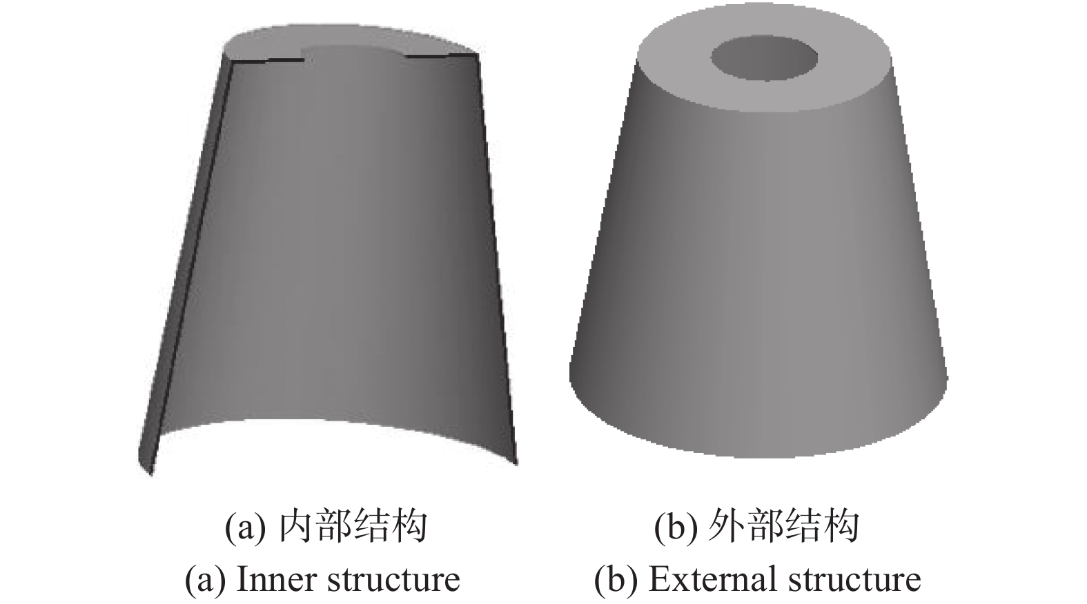
根据以上推测,按光路传播规律[8],重新设计2号冷屏结构,新设计的冷屏结构为4号结构。仿真分析数据见表3。
No.4 Cold shield height/mm 29 Effective radiation(dimensionless) 3.18E+02 Stray radiation(dimensionless) 7.20E+01 Table 3. Simulation analysis data

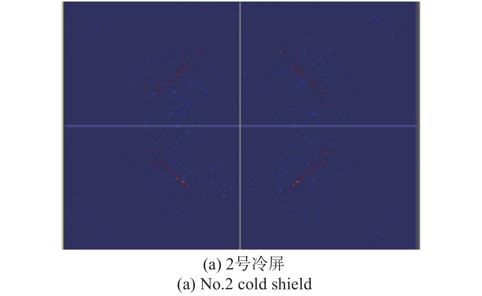
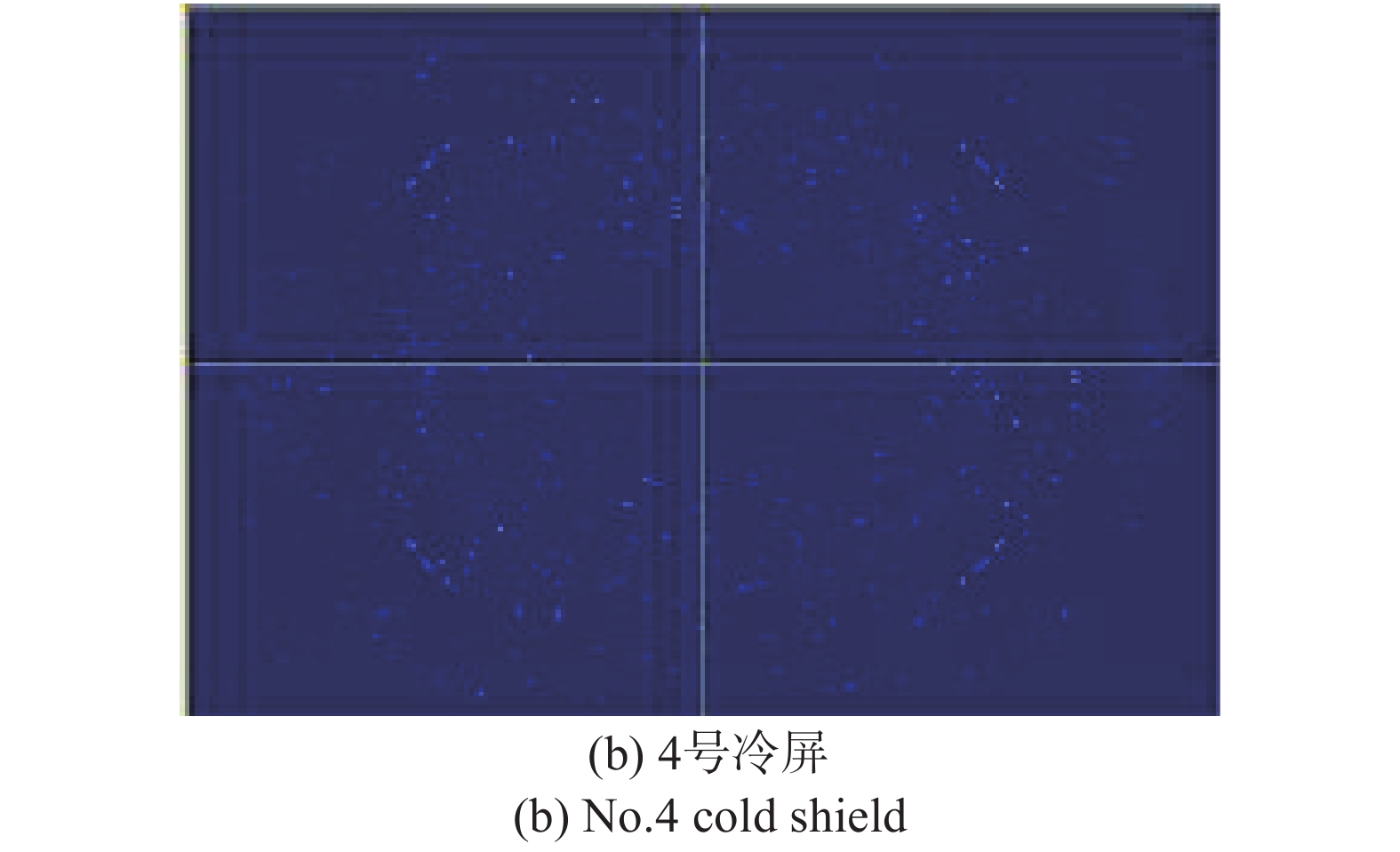
冷屏有效抑制杂散辐射时,有效辐射能量与非有效抑制冷屏结构相同。表2与表3中1号、3号和4号冷屏仿真结果相比较,随着冷屏高度增高,杂散辐射的增幅为1.2和8.8,有效辐射的增幅为16和37,有效辐射的增幅远大于杂散辐射的增幅,对冷屏效率的提高利大于弊。2号和4号的杂散辐射能量分布仿真结果如图8所示。

Figure 8. Stray radiation energy diagram
能量分布仿真图中显示,2号的杂散辐射分布非常不均匀,并且个别位置能量呈红色,能量很高。4号冷屏整个像面的杂散辐射分布较均匀,能量差别小,与4号冷屏测试的非均匀性优于2号冷屏的测试结果一致。
选取4号冷屏进行探测器组件对比测试,测试数据见表4。
No.4 No.2 Cold shield structure Restrain effectively Restrain ineffectively Non-uniformity 4.87% 6.11% Table 4. Test data
表4中,2号与4号冷屏高度相同,4号冷屏有效抑制杂散辐射,非均匀性相较2号降低1.24%,冷屏效率提高。
1号、3号和4号有效抑制杂散辐射的冷屏结构对比如图9所示[9]。

Figure 9. Restrain the stray radiation effectively
图10显示冷屏有效抑制杂散辐射时,冷屏高度增高,冷屏效率提高,探测器组件非均匀性变小。

Figure 10. Test data
-
为提高冷屏效率,F数不变,采取加高冷屏高度的方法;冷屏高度增高时,冷屏底端不变,冷屏外壳结构有改变倾角和改变顶端外径两种方式,如图11所示。选取的变换方式不同,冷屏杂散辐射抑制能力也不同,为进一步优化冷屏结构[10],提高冷屏效率,需要对两种变换方式进行对比分析。

Figure 11. Cold shield structure changed
冷屏改变倾角和改变顶端外径包含有效抑制杂散辐射和非有效抑制杂散辐射两种结构。首先仿真非有效抑制杂散辐射结构,仿真对比数据如图12所示。

Figure 12. Restrain ineffectively
图12中,非有效抑制杂散辐射冷屏结构,顶端和倾角的变化对有效辐射都没有影响,杂散辐射受影响较大,增高4 mm时,倾角变化与顶端变化相差尤其明显。
然后仿真有效抑制杂散辐射结构,仿真对比数据如图13所示,能量分布图如图14所示。

Figure 13. Restrain effectively

Figure 14. Stray radiation
从仿真数据和能量分布图分析,有效抑制杂散辐射冷屏结构,顶端和倾角的变化对有效辐射和杂散辐射都没有影响。
为验证与实际测试的一致性,选取顶端和倾角变换方式不同的两组有效抑制杂散辐射冷屏结构进行测试。顶端与倾角变换,冷屏测试非均匀性分别为4.44%和4%、5.24%和5.22%,与仿真结果基本一致。
-
冷屏结构与冷屏效率的分析为冷屏结构设计提供了一种新思路。冷屏有效抑制杂散辐射时,冷屏高度增高,冷屏效率提高,探测器组件非均匀性减小,性能变好。冷屏不能有效抑制杂散辐射,冷屏高度变化,冷屏效率变化趋势需要仿真分析判断。
有效抑制杂散辐射冷屏结构,顶端和倾角的变化对有效辐射和杂散辐射都都没有影响。未有效抑制杂散辐射的冷屏结构,顶端和倾角变化对有效辐射都没有影响,对杂散辐射影响大,冷屏效率变化趋势需要仿真分析判断。冷屏结构与冷屏效率的分析研究对冷屏结构设计有一定的参照意义。
Structure and efficiency of cold shield
doi: 10.3788/IRLA20200223
- Received Date: 2020-06-07
- Rev Recd Date: 2020-07-27
- Available Online: 2021-05-12
- Publish Date: 2021-03-15
-
Key words:
- cold shield of infrared detector /
- structure of cold shield /
- cold shield efficiency /
- restrain effectively
Abstract: The cold shield structure has direct effects on stray lights suppressing in infrared detector. In order to further improve the cold shield efficiency, the cold shield height and containment structure influence on stray radiation suppressed were offered based on the analysis. Building mathematical models, DF20 cold shield was chosen as an instance to be calculated by the program. Compared with the test results of the infrared detector, when the cold shield height is 25 mm, the test result is 5.46%. When the cold shield height is 29 mm, the test result of cold shield which restraining the stray radiation effectively 4.87%, the test result of cold shield which restraining the stray radiation ineffectively 6.11%. A creative idea of cold shield structure design was proposed. Just increasing the cold shield height, may not increase the cold shield efficiency. When the baffles restrained the stray radiation effectively, with the cold shield hight increased, the stray radiation suppression capability became stronger, the cold shield efficiency increased, the infrared detector performance was improved. At the same time, changing the cold field structure will not influence the efficiency of the cold shield.


 DownLoad: