


HTML
-
水下蓝绿激光具有准直性好、定位精度高、抗干扰能力强等优点,在水下通信和探测领域得到广泛应用[1-3],主要应用领域包括水下光通信[4-7]、水下测距成像[8-13]、海底地形探测[14-17]、近程交会探测[18]等方面。水下光通信研究主要集中在通过光束调制增加传输容量,减少传输损耗和误码率,如Li和Cheng等分别研究了拉盖尔-高斯涡旋光不同调制模式下的传输能力和信道容量[19-20]。水下测距成像研究常使用距离门选通方式,如加拿大的LUCIE系统[21]和欧洲的SeaLVi系统[22],但距离门选通将在选通门外产生探测盲区,而且扩束照明使能量随距离衰减加快,不利于对非合作目标的探测,Aurora等研究的单光子探测系统需要用统计方式成像[12],不适合实时探测。海底地形探测常采用扫描探测方式[23]。Ouyang Bing等研制了压缩感知成像系统,采用数字微镜器件(Digital Micromirror Device, DMD)将光场进行压缩编码,对载具驶过的海底区域进行扫描还原[24];Simon Stemmler等研制了飞行时间激光扫描探测系统,通过旋转8棱镜发射线光束进行扫描探测,可以重建水下物体的三维图像[25];Tu Dawei等设计的系统则通过旋转平面镜发射激光条纹进行扫描探测实现三维探测[26]。上述系统主要对海底静态的地形和物体进行探测,扫描区域在一固定窗口,无法周向覆盖。查冰婷、甘霖等提出周向扫描的探测系统[10, 18]:该系统在舱壁开环形窗,通过旋转轴心平面镜实现光束的周向发射,可实现对近程交会的非合作运动目标的周向探测。但该方案要求几乎整个舱段为透明光学材料,即使用金属加强筋进行加固,仍可能因受到冲击造成窗口损坏。另外,若近程探测的目标为水下小型高速运动目标,所需光束的发射频率较高,相邻发射光束间隔角度较小,当相邻发射光束夹角小于加强筋的圆周角时,会给目标探测带来一定的扇形盲区。为解决环窗结构光学窗口面积过大带来的结构强度不足和加强筋带来扇形盲区问题,文中提出一种转移扫描基点的发射系统。通过该系统将发射光束扫描中心,从圆柱舱段中轴转移到舱体壳体下表面附近,并且重整了扫描的总视场角。不但大大减小了壳体开窗所需的面积,消除了加强筋带来视场盲区,而且避免了环窗设计光路对舱内空间的占用。Zemax系统的仿真结果表明,该设计可较好地满足水下周视探测的发射系统的需求。
-
系统设计的总体要求是:舱内半径为160 mm,以转镜反射点中心作为起点,舱内光路总长度应小于160 mm。探测系统要求探测光束间隔均匀,由于像场畸变导致的光束发射角度偏差控制在1%以内。该类探测系统要求光束能量集中[27],典型目标的直径为300 mm,当要求最大探测距离为20 m时,到达目标的光斑直径不超过目标直径的1/3,则光束发散角不超过5 mrad。为保证有足够的能量用于探测,镜组的能量传输效率应不低于95%。
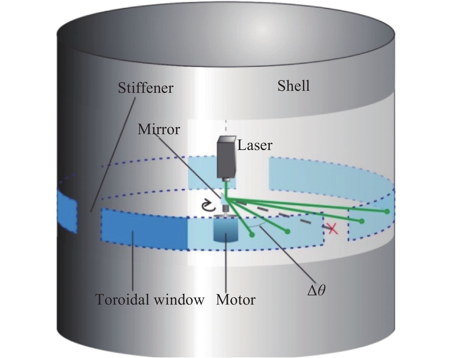
水下单光束周视扫描探测系统在圆柱型载具采用的环形窗设计如图1所示。

Figure 1. Sketch of torus window detection transmitting system design
在系统中,激光器以一定的发射频率发射探测光束,驱动马达按激光发射频率同步驱动反射镜以均匀的步进角
$\Delta \theta $ 进行转动,探测光束经过反射镜转向后穿过环形发射窗口,对外部进行周向扫描。虽然使用加强筋进行加固,大面积环形玻璃窗仍带来一定的结构强度风险。另外,加强筋将遮挡部分扫描点,这些被遮挡的发射点将导致周向探测的扇形盲区。且这种方案还受另一局限:由于发射光路中间不能产生遮挡,载具内其他系统的供能和通信走线只能紧贴加强筋舱壁的有限空间进行布置,造成空间利用不便。为了避免环窗设计带来的上述问题,文中提出了一种利用开普勒望远镜结构转移扫描基点的发射光学系统结构。将出瞳和转镜中心设置在开普勒望远镜结构的物镜前焦点上,通过系统对不同角度
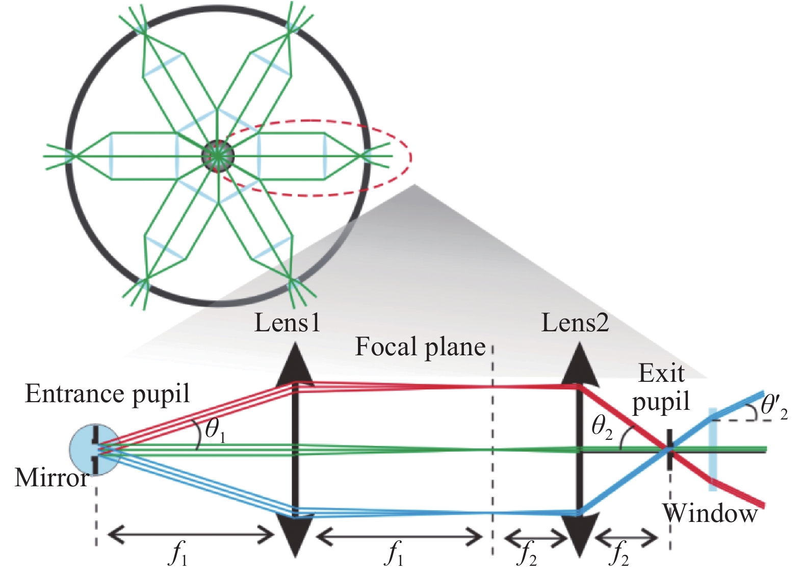
${\theta _1}$ 入射的光束进行变换,在系统目镜组出瞳位置实现光束以不同角度${\theta _2}$ 发射,两组镜片共同组成扫描基点转移系统。在舱体径向上平均排布6路镜组,将扫描点从舱体中心转移到舱体表面附近,最后光束通过舱体表面的窗口进入水体进行扫描探测,窗口与舱体采用O形圈进行静密封,压圈压接螺纹涂硅橡胶。6路发射系统结构示意图如图2所示。
Figure 2. Sketch of 6-group transmitting system
每一路结构中,转镜中心放置在前组入瞳,且恰好位于物方焦面。光源为具有一定面积的高斯光源,而非理想点光源,因此在前组入瞳处设置一定大小的入射光阑,与入射高斯光束束宽相当。若能约束主光线垂直入射像面,前组实际上变成了一个像方远心结构[28-29],后组结构类似:结构为前组镜向,出瞳位于焦面,像方主光汇聚点位于像方无限远。将前后组焦平面重合,则不同角度平行入射的光束将按一定的对应关系平行出射,从而实现对探测光束发射角度的控制。
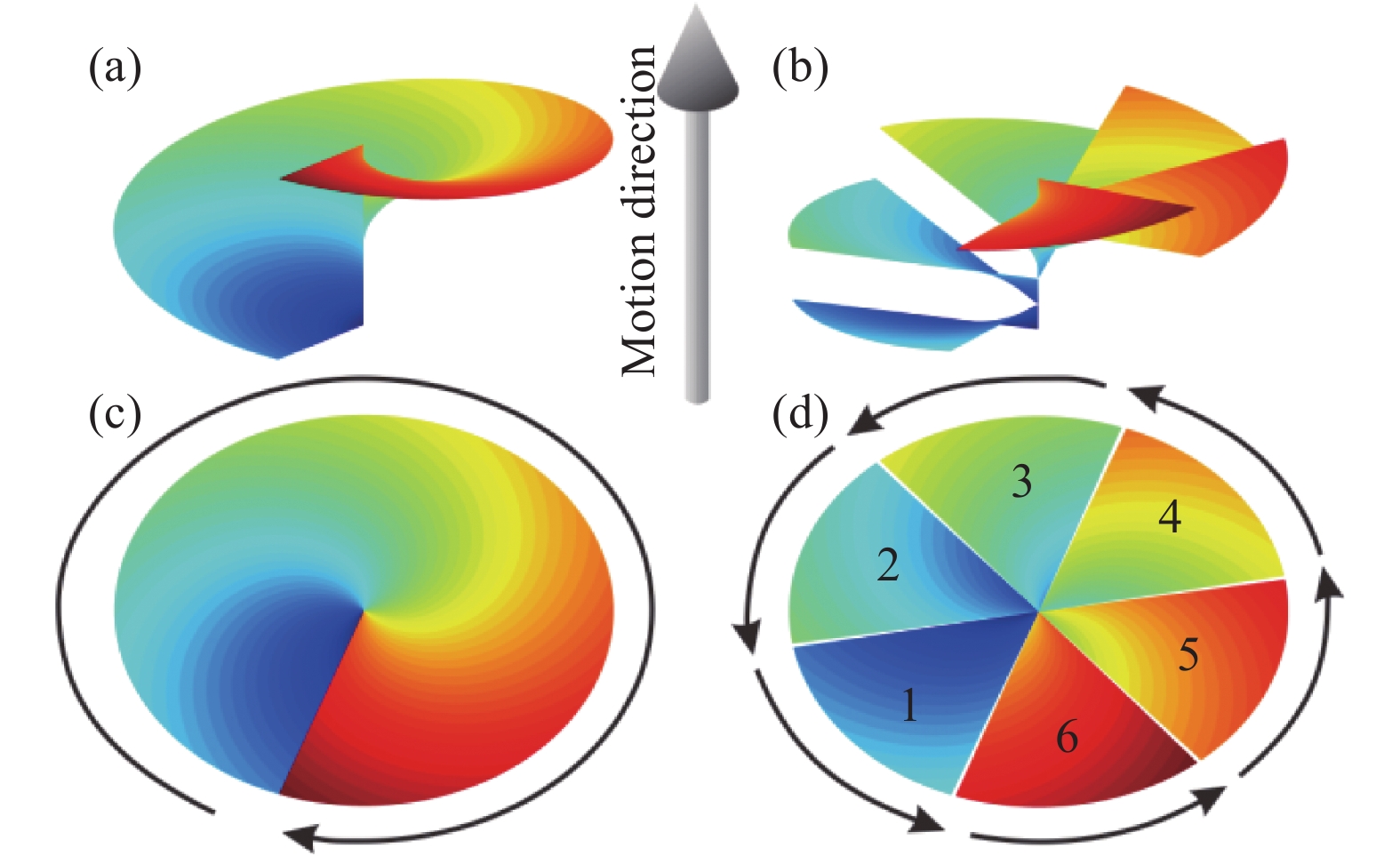
与环窗方案不同的是,在6路4f系统中,光束从上一路镜组到下一路镜组,每个扇区将经历扫描方向的周期性切换,按扇区依次完成360°扫描。当舱体向前做匀速直线运动时,环窗设计和4f设计扫描光束的包络面如图3所示。

Figure 3. Scan beam envelops: (a), (c) side elevation and platform for toroidal window; (b), (d) side elevation and platform for 4f system
当舱体按图示运动方向前进,位于舱体中轴的马达以顺时针方向驱动中心反射镜时,环窗设计发射光束形成一个螺旋状的连续包络,光束扫描方向也为顺时针方向;而4f系统形成扇形的周期性包络,每个扇区的扫描方向为逆时针方向。从弹头方向俯视,如二者初始扫描方向一致,环窗系统将如图3(b)顺时针完成扫描;而4f系统将按1~6的扇区顺序依次完成每个扇区的扫描,每个扇区进行的扫描均按逆时针方向。
-
望远镜前组的物镜组通常只具有较小的视场,因此使用一个3片式柯克摄影物镜代替望远镜物镜作为前组,采用像方远心设计对前组进行优化。后组的光线传播过程为前组的镜向同样采用像方远心设计优化方法,对优化结构进行反向即可得到后组结构。
激光器发射的高斯光束直径为1 mm,将物方入瞳直径设置为1.155 mm,以保证光束以30°倾角入射时不发生遮挡。
为避免相邻两路的前组镜片不发生结构干涉,每一路前组的总扫描角度应小于60°,故设置前组的最大有效入射角度
${\theta _{1\max }}$ =28°。为给转镜预留空间,入瞳距离设置为20 mm。由于探测系统用于海洋环境,对耐潮、耐水、耐候性能具有较高要求,根据成都光明玻璃库的玻璃耐潮、耐水、耐候性能,可选取H-BAK1和H-ZF7LA玻璃作为镜片材料。
若舱体表面采用平板玻璃作为窗口,由于舱内介质折射率
${n_a}$ =1,舱外海水折射率${n_w}$ =1.333,后组发射角度${\theta _2}$ 应大于前组入射角度${\theta _1}$ ,以确保探测光束从每一路的窗口进入水中的最大角度为${\theta ^{'}}_2$ =30°。根据折射定律计算,后组的最大发射角度${\theta _{2\max }}$ 应为41.799°。较大的F数有利于控制像差。因为入瞳直径d已经确定,为了增加F数,应使镜组具有较大的焦距。不考虑畸变的影响,焦距
$f$ 、像高$y$ 、视场角$\theta $ 、入瞳$d$ 、$F$ 数关系如公式(1)、(2)所示:发射光路实际上是一个低倍的缩束变倍光路,根据公式(1)可得图2中前后组焦距的关系:
因此,增加像高可以使镜组获得较大的
$F$ 数。预留给系统的舱段高度50 mm,故将镜组的最大直径约束到45 mm以内,并通过DMVA操作数约束前后组的像高均为40 mm。在不考虑畸变的情况下,与像高和入瞳匹配的相应的前组焦距${f_1}$ 为37.615mm,后组焦距${f_2}$ 为22.370 mm。从前组平行入射的光束呈锥状汇聚到像面,为了增大后组$F$ 数,减小后组设计难度,则光束出射的束宽变窄对设计较为有利,因此前组保留较大的后截距,后组保留较小的后截距较为合理。为前组分配90 mm的空间,后组分配60 mm的空间,后组的物方光阑到舱体发射窗口表面预留10 mm空间。前组、后组的初始的结构参数如表1所示。Former group parameter Value Latter group parameter Value Image height/mm 40 Image height/mm 40 f1/mm 37.615 f2/mm 22.370 Total length/mm ≤90 Total length/mm ≤60 Field/(°) ±28 Field/(°) ±41.799 Table 1. Parameter of original structure
首先对前组进行优化,并以前组的优化设计作为后组的初始结构,仍用像方远心设计进行优化,优化完成将镜组反向,得到的前、后组结构参数,舱内转移光路如图4所示。
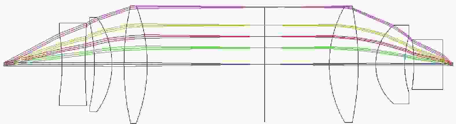
Figure 4. Structure of transmitting system
初步优化后的前、后组参数如表2所示。
Former group parameter Value Latter group parameter Value Image height/mm 40.000 Image height/mm 40.000 f1/mm 39.669 f2/mm 27.045 Total length/mm 90.000 Total length/mm 60.000 Field/(°) ±28 Field/(°) ±41.799 Table 2. Parameter after primary optimization
初步优化后发射系统的最大发射角度
${\theta _{2\max }}$ 达到41.799°,满足出平板窗后覆盖±30°扫描视场的要求。 -
设计中期望
${\theta _1}$ 到${\theta _2}$ 的映射具有线性关系。按光学设计的一般规则,查看0、0.3、0.5、0.7、1等5个相对视场入射光线在前、后组像面的高度。由于系统畸变,初步优化的系统中,二者0°、8.4°、14°、19.6°、28°5个视场角入射的光线在像面高度的分布并不一致,如表3所示。${\theta _1}$/(°) Former group image height/mm ${\theta _2}$/(°) Latter group image height/mm 0 0 0 0 8.4 5.826 12.540 5.903 14 9.743 20.900 9.863 19.6 13.729 29.259 13.706 28 19.990 41.799 19.932 Table 3. Image height of former and latter group
利用畸变命令查看光束以0.56°间隔从前组入射,从后组射入空气中的角度分布情况,如图5所示。
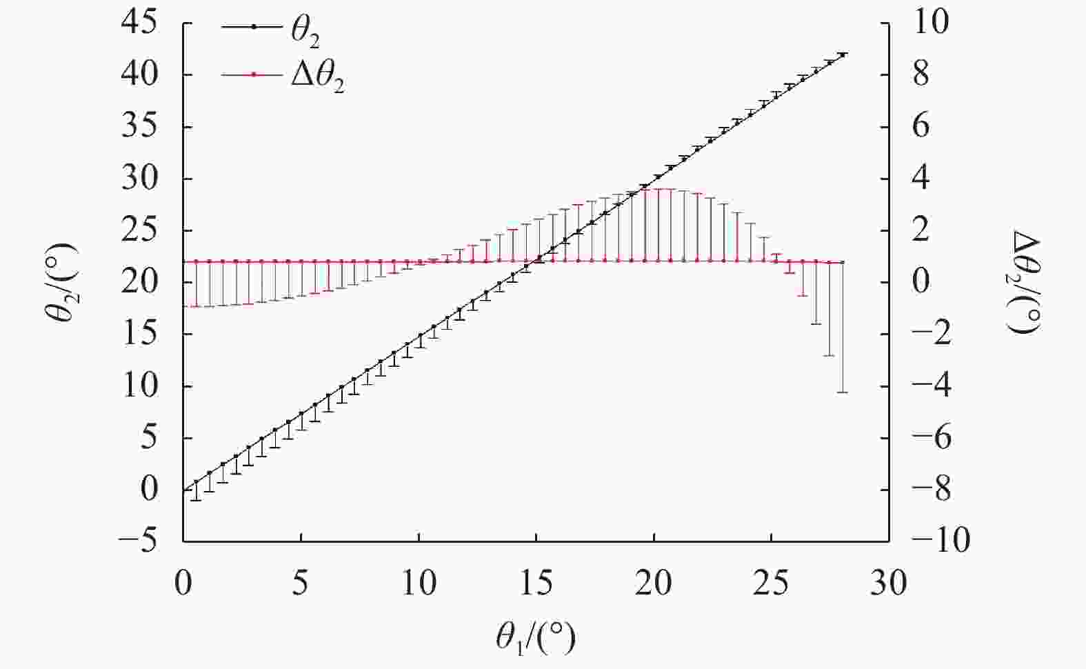
Figure 5. Transmitting angle error in air
理想的发射角与入射角
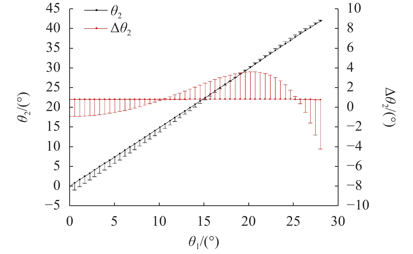
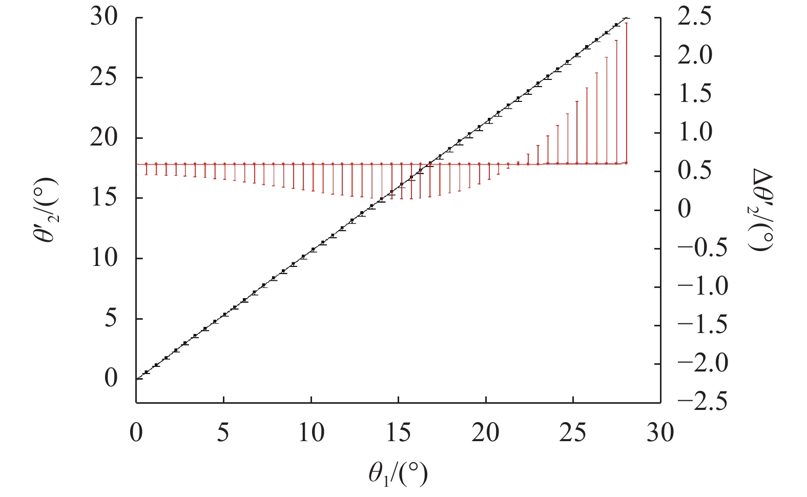
${\theta _1}$ 具有线性关系。图中用误差棒给出了${\theta _2}$ 与理想发射角的偏差。因为发射角的偏差,相邻后组发射光束的间隔$\Delta {\theta _2}$ 也并不均匀,从误差棒数据看,最大误差约6%。在出窗经历水下传播后,误差的放大可能对探测造成较大的影响。为了解决深水抗压问题,在后组出瞳后5 mm处,需要增加厚度为5 mm的平板H-BAK1玻璃窗。由于光束并非完全平行,平板玻璃窗两侧介质存在的折射率差异导致水下光束的传播偏差增大。查看同样以0.56°间隔入射的光束出窗后在水下传播的情况,绘制不同入射角度的光束发射角,并给出相邻发射光束夹角,如图6所示。

Figure 6. Underwater propagation angle deviation of the beam
前组入射的光束角度为0°和28°时,由于像高约束,发射角与0°、30°的偏差几乎为0。但由于畸变的不一致,当进入前组的光线以0°~22.2°入射时,发射角增长的斜率大于理想的斜率,相邻光束间隔偏大;当进入前组的光线以22.2°~28°入射时,发射角增长的斜率小于理想的斜率,相邻光束间隔偏小。在接近28°的大入射角条件下,相邻发射光束的夹角仅0.513°,相对0.6°的参考值的误差达到−14.493%。
引起这一误差的根本原因是,前后组角度的线性对应关系并未在优化中受约束,导致前后组相应视场角在像面的像高并不具有一致性。设计中希望
${\theta _1}$ 、${\theta _2}$ 通过像高建立良好的线性关系,于是提出一种畸变匹配的优化方法。引入
$f - \theta $ 镜头设计中的畸变控制方法[30],Zemax中,$f - \theta $ 畸变量由公式(4)决定:式中:
${D_1}$ 代表前组$f - \theta $ 畸变;${D_2}$ 代表后组$f - \theta $ 畸变;${y_1}$ 、${y_2}$ 分别代表前、后组在像面的像高;${f_1}$ 、${f_2}$ 分别代表前、后组的焦距。由公式(3)可知,当
$f - \theta $ 畸变为0,前、后组像高均正比于入射角。由于像高已经通过DMVA操作数约束一致,只要$f - \theta $ 足够小,就可以满足相邻发射光束间隔均匀的要求。系统中对畸变进行约束的操作数为DIST和DIMX,但二者并不直接对
$f - \theta $ 畸变进行约束,引入Zemax系统标准光学畸变量公式(5):$\theta $ 较小时,其值与正切值近似相等,标准畸变近似等于$f - \theta $ 畸变;随着角度增大,正切值增长会大于$\theta $ 增长,当$f - \theta $ 畸变取值为0时,标准畸变取得负值。因此,前、后两组均在像面发生桶形畸变,且后组在边缘的畸变百分比绝对值大于前组。保持前组不变,通过公式(4)、(5)得到前组的标准畸变像差
${D_{1s}}$ ,通过匹配前、后两组的$f - \theta $ 畸变,利用前组标准畸变对后组的标准畸变进行计算,可以保证前、后组的$f - \theta $ 畸变近似一致,入射角度和发射角度具有良好的线性匹配关系。计算前组入射角度为最大入射角的0°、8.4°、14°、19.6°、28°时的前组实际像面高度,使用EFFL操作数固定
${f_2}$ ,联立公式(4)、(5),代入后组线性对应的${\theta _2}$ ,计算同一像高时的${D_{2s}}$ 。使用DIMX和DISC操作数控制相应入射角${\theta _2}$ 的畸变参数进行优化,优化后的采用平板窗的整组结构如图7所示。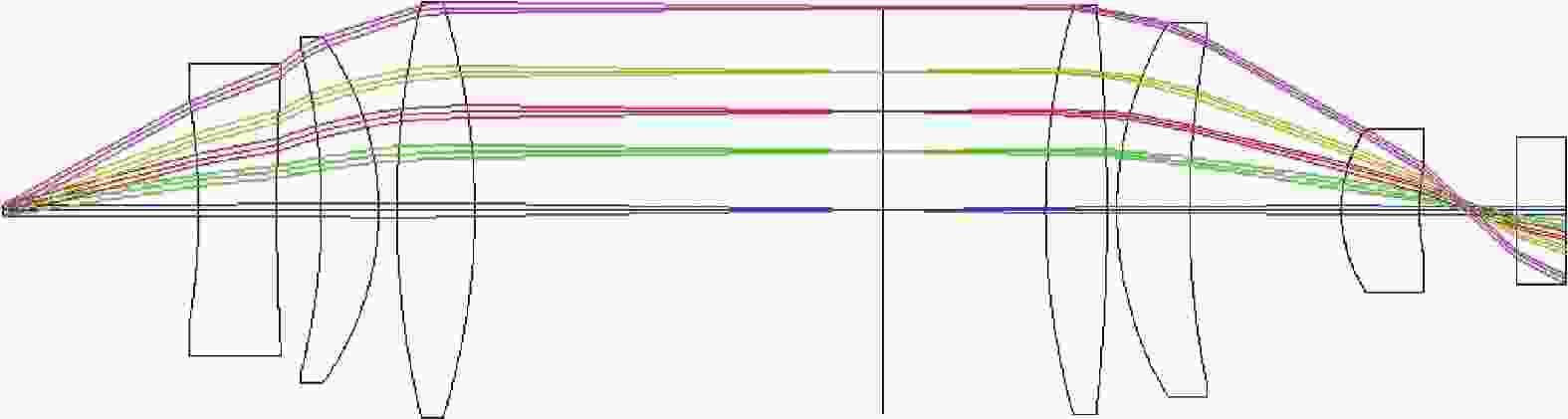
Figure 7. Plane window emission system structure
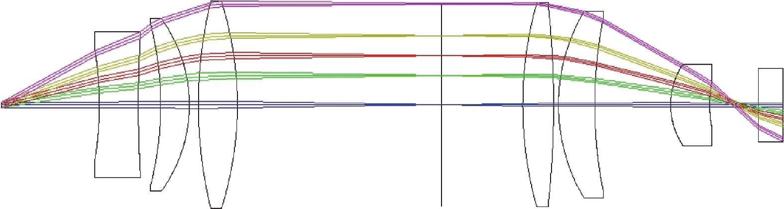
若外壳表面的发射窗口要求匹配载具外形,需将平板窗口替换为柱面外形,若使用平凸的柱面镜,发射的光束将会因圆弧表面在出舱后的弧矢方向聚焦,并在远场发散,导致能量过分分散,对探测造成不利影响。因此基于平板窗角度优化的后组设计将平板窗改为柱面的共形窗口,将内侧平面也设置为可变曲率的柱面,并利用像方远心方法继续优化,优化后的共形窗如图8所示。

Figure 8. Conformal window structure after optimization
共形优化的后组曲率和厚度有微小变化,优化后两种方案的透镜参数见表4和表5。
Lens Surface Surface type Radius/mm Thickness/mm Material Semi-diameter/mm Stop Standard Infinity 20.000 Air 0.577 L1 1 Standard −64.875 7.999 H-BAK1 10.736 2 Standard 245.825 4.563 Air 14.397 L2 3 Standard −62.429 5.870 H-ZF7LA 15.940 4 Standard −28.195 1.844 Air 17.045 L3 5 Standard 83.148 8.000 H-BAK1 20.280 6 Standard −65.614 41.725 Air 20.513 Focus plane Standard Infinity 16.725 Air 20.000 L4 7 Standard 72.584 6.308 H-BAK1 20.196 8 Standard −178.896 1.000 Air 19.981 L5 9 Standard 35.081 7.426 H-ZF7LA 18.457 10 Standard 83.958 15.541 Air 16.967 L6 11 Standard 13.985 8.000 H-BAK1 8.067 12 Standard 22.229 10.000 Air 4.536 L7 13 Standard Infinity 5.000 H-BAK1 4.816 14 Standard Infinity 20000.000 Water 7.233 Image Standard Infinity 0.000 Water 11552.561 Table 4. Prescription for transmitting system with plane window
Lens Surface Surface type Radius/mm Thickness/mm Material Semi-diameter/mm Stop Standard Infinity 20.000 Air 0.577 L1 1 Standard −64.875 7.999 H-BAK1 10.736 2 Standard 245.825 4.563 Air 14.397 L2 3 Standard −62.429 5.870 H-ZF7LA 15.940 4 Standard −28.195 1.844 Air 17.045 L3 5 Standard 83.148 8.000 H-BAK1 20.280 6 Standard −65.614 41.725 Air 20.513 Focus plane Standard Infinity 15.812 Air 20.000 L4 7 Standard 76.049 6.190 H-BAK1 20.184 8 Standard −172.721 1.000 Air 19.982 L5 9 Standard 35.089 8.000 H-ZF7LA 18.487 10 Standard 76.462 16.200 Air 16.750 L6 11 Standard 12.782 7.798 H-BAK1 7.894 12 Standard 20.508 10.000 Air 4.523 L7 13 Toroidal −235.145 5.000 H-BAK1 4.710 14 Toroidal −160.000 20000.000 Water 7.117 Image Standard Infinity 0.0000 Water 11552.735 Table 5. Prescription for transmitting system with conformal window
除窗口玻璃外,所有镜片均为球面设计,仅共形窗为双面柱透镜,具有良好的可加工性。由于前、后组共焦面设计,故第2、5、6片为弯月镜,减少了前、后组的场曲,
-
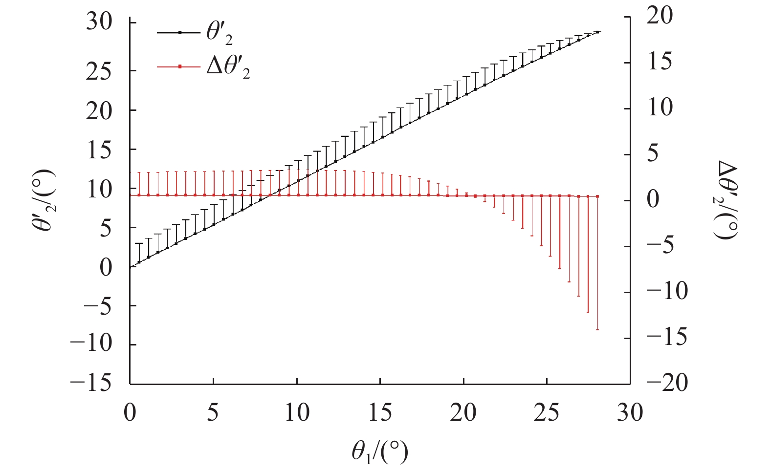
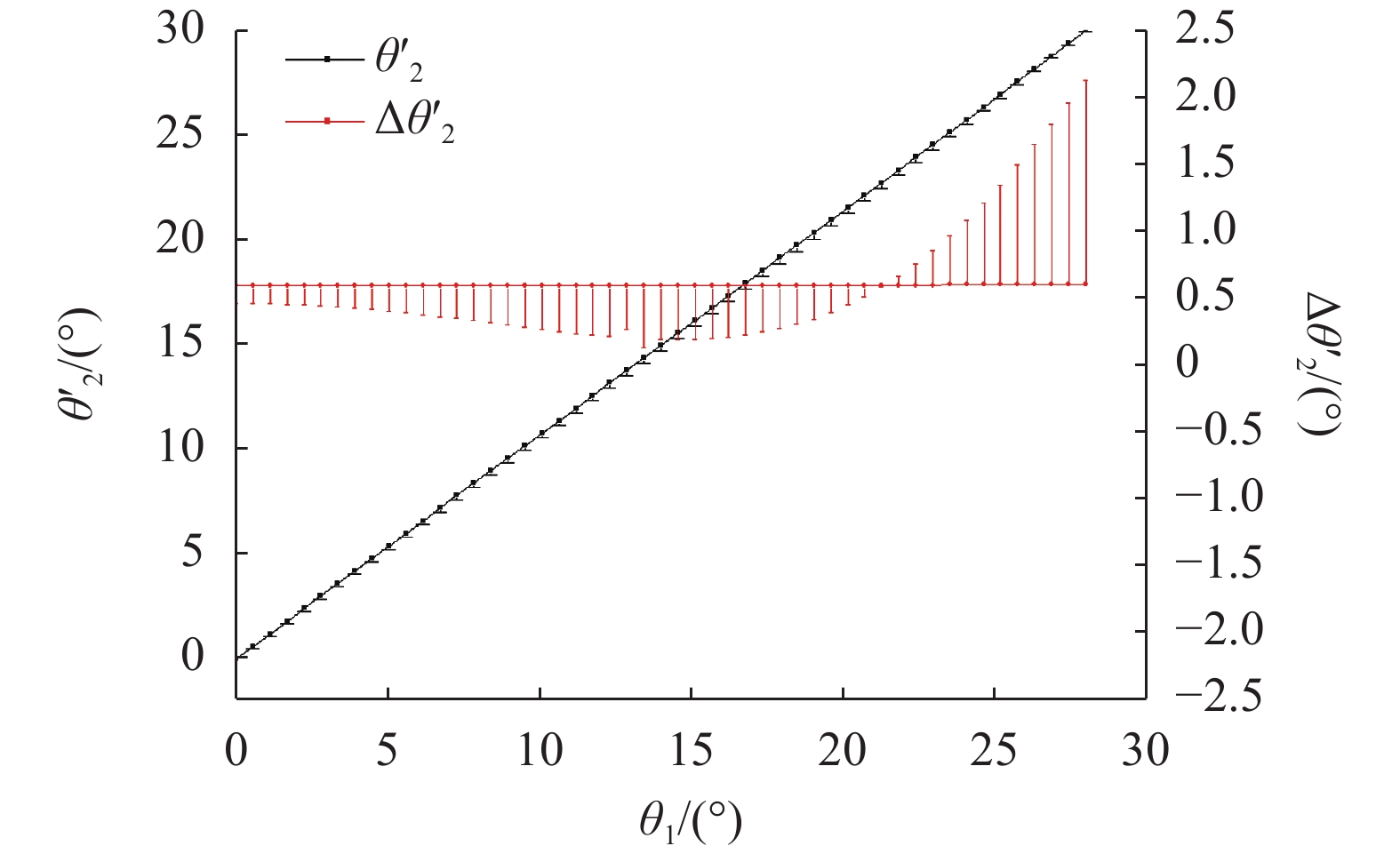
通过畸变数据文件,查看光束分别经过平板窗设计和共形窗设计两种转移发射旋转基点的发射系统,光束从窗口发射进入水中的角度偏差。平板窗设计的偏差如图9所示,共形窗设计的偏差如图10所示。
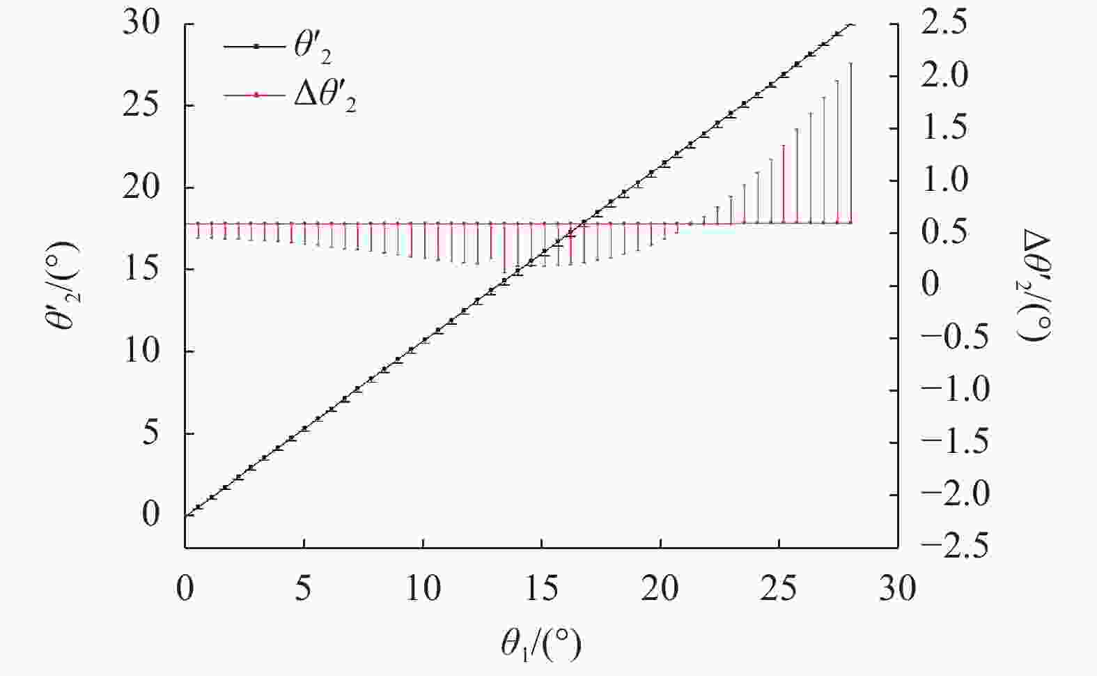
Figure 9. Transmitting angle error of plane window system in water
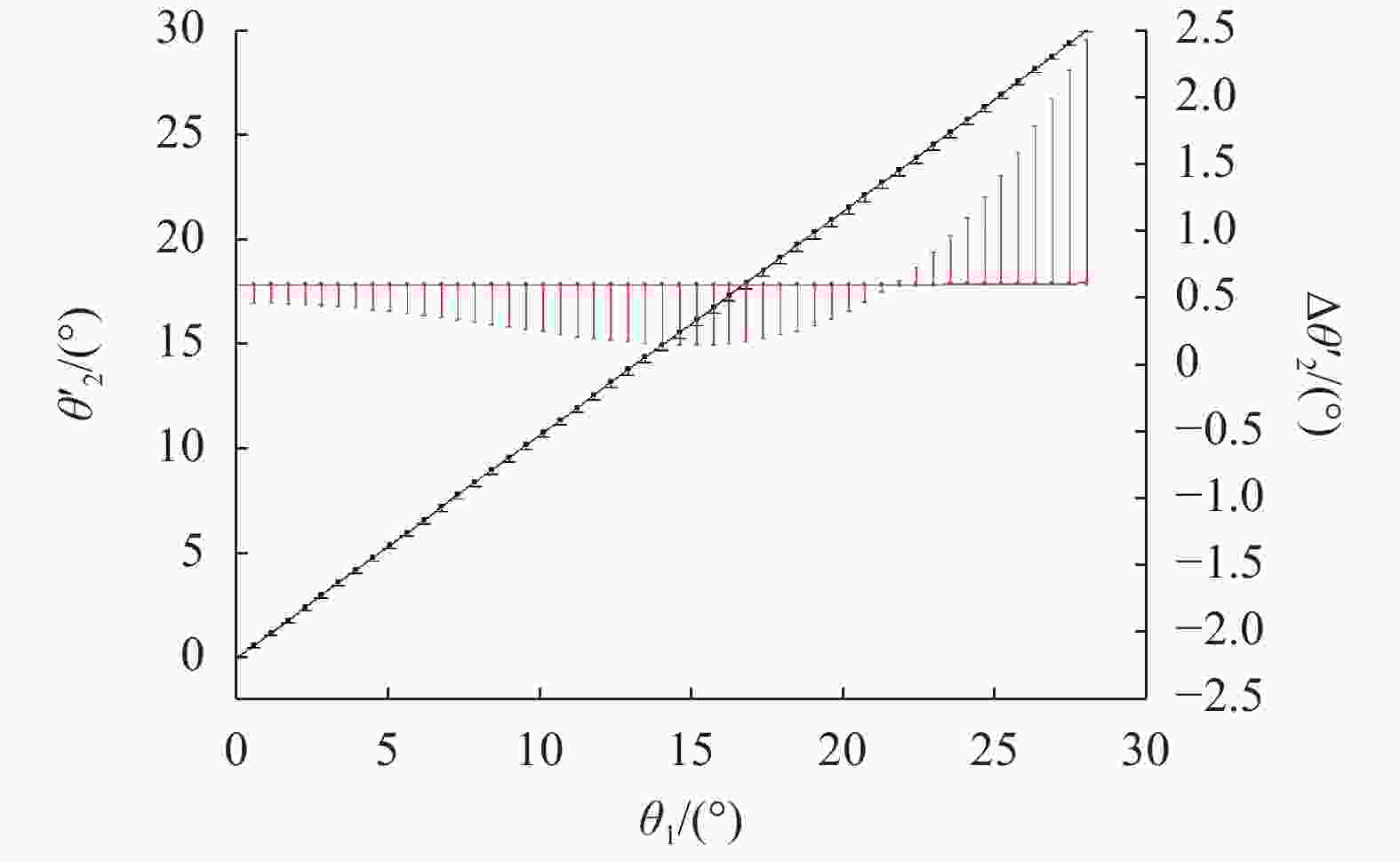
Figure 10. Transmitting angle error of conformal window system in water
两种设计发射角度偏差均不超过0.4%,以0.6°间隔发射时,相邻光束对0.6°的偏差不超过2%。当探测距离为20 m时,相邻光束中心理论间隔为209.3 mm,该系统发射光束的间隔与理论间隔的绝对差值小于4 mm。
-
由于假想探测目标直径为300 mm,为了使光斑直径在20 m的探测距离上不大于目标直径1/3,经过发射系统后,激光的发散角应不大于5 mrad。利用Zemax物理光学传播仿真模拟了分别以0°、8.4°、14°、19.6°、28°入射,初始半径为0.5 mm,初始发散角为1 mrad的高斯光束,经过发射系统调整,在水下传播20 m后的光束半径和发散角。平板窗设计的发射结果如表6所示,共形窗设计的发射结果如表7所示。
${\theta _1}$/(°) X beam size/mm X divergence/mrad Y beam size/mm Y divergence/mrad 0 30.618 1.513 30.618 1.513 8.4 26.931 1.313 27.227 1.311 14 20.746 0.986 22.333 1.026 19.6 12.784 0.584 18.375 0.786 28 10.098 0.446 27.975 1.034 Table 6. Plane window design beam divergence
${\theta _1}$/(°) X beam size/mm X divergence/mrad Y beam size/mm Y divergence/mrad 0 26.402 1.303 31.576 1.561 8.4 22.553 1.097 27.943 1.346 14 16.208 0.768 22.732 1.044 19.6 9.028 0.413 18.611 0.797 28 14.700 0.649 29.755 1.101 Table 7. Conformal window design beam divergence
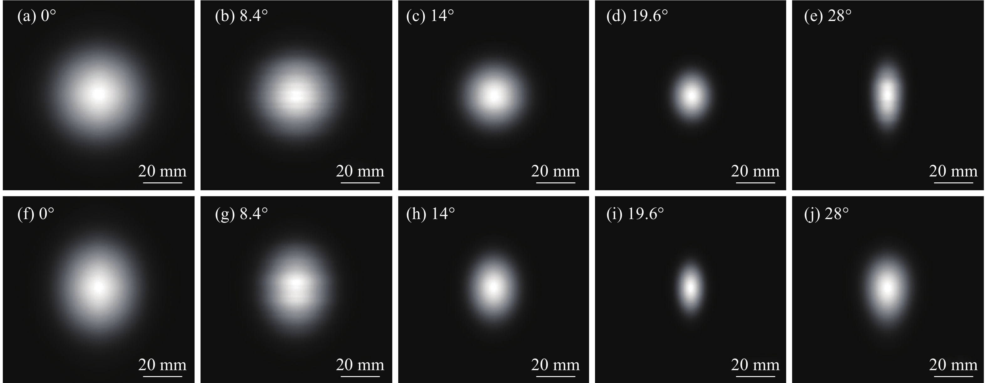
平板窗方案的水下发射光束的最大发散角为1.513 mrad,水下传播20 m最大均方根(RMS)光斑半径为30.618 mm;共形窗方案的水下发射光束最大发散角为1.561 mrad,水下传播20 m最大RMS光斑半径为31.576 mm。利用物理光学传播仿真模拟了5个入射角下20 m外的光斑的图像如图11所示。光斑中心X方向能量分布如图12所示。

Figure 11. Beam section spot after 20 m under water propagation:(a)- (e) Spot of plane window system; (f)-(j) Spot of conformal window system

Figure 12. Spot energy distribution: (a)-(e) Spot energy distribution of plane window system; (f)-(j) Spot energy distribution of conformal window system
像面大小统一调整为100 mm×100 mm,光束的初始能量统一设置为1 W,仿真结果表明,光斑仍近似高斯分布。不计玻璃和水介质的反射和吸收损失,到达像面的能量均达到99.9%以上,光斑最大直径均小于100 mm。
-
由于镜片较多,如不镀增透膜,则出窗前因为各个光学面的反射,探测光束就将产生较大的能量损失。利用Zemax查看未镀膜时两种设计方案能量传输效率如表8所示。
${\theta _1}$/(°) Efficiency (plane window) Efficiency (conformal window) 0 47.0214% 46.9997% 8.4 47.0576% 47.0356% 14 47.1184% 47.0960% 19.6 47.1941% 47.1730% 28 47.2029% 47.2045% Table 8. Coating-less transmission efficiency
从表8数据得知,未镀膜时因为各表面反射损失,出窗后的能量不足初始能量的50%。
若对各表面镀增透膜,比较0.995和0.999两种增透膜对像面能量的影响,镀膜后两种设计方案的传输效率如表9和表10所示。
${\theta _1}$/(°) Efficiency (plane window) Efficiency (conformal window) 0 90.935% 90.893% 8.4 91.006% 90.963% 14 91.132% 91.088% 19.6 91.320% 91.276% 28 91.719% 91.679% Table 9. 0.995-coating transmission efficiency
${\theta _1}$/(°) Efficiency (plane window) Efficiency (conformal window) 0 95.803% 95.759% 8.4 95.878% 95.833% 14 96.011% 95.965% 19.6 96.210% 96.163% 28 96.629% 96.587% Table 10. 0.999-coating transmission efficiency
镀0.995的增透膜后,能量传输效率可达90%以上;镀0.999的增透膜后,能量传输效率可达95%以上。为满足设计需求,镜组需镀99.9%增透膜保证能量传输效率。
-
设置各面加工面型精度±0.1 mm,偏心±0.1 mm,各玻璃元件倾斜公差±0.1°,折射率和阿贝数采用默认设置,分别为0.001和1%。140个参数,总计140个公差数,故设蒙特卡洛仿真次数19600次。仿真的目标为RMS spot radius,仿真结果如表11、表12所示。
Probability RMS spot radius/mm 0° 8.4° 14° 19.6° 28° 98%≤ 9.603 9.877 9.878 18.675 18.697 90%≤ 8.895 9.092 9.074 17.993 17.986 50%≤ 7.609 7.695 7.673 16.848 16.826 10%≤ 6.324 6.324 6.309 15.760 15.734 2%≤ 5.599 5.553 5.506 15.164 15.122 Table 11. Tolerance analysis result of plane window
Probability RMS spot radius/mm 0° 8.4° 14° 19.6° 28° 98%≤ 8.713 12.909 12.969 22.557 22.596 90%≤ 7.949 12.026 12.057 21.775 21.792 50%≤ 6.584 10.507 10.521 20.498 20.511 10%≤ 5.260 9.036 9.071 19.305 19.332 2%≤ 4.537 8.241 8.263 18.683 18.684 Table 12. Tolerance analysis result of conformal window
加工和装配公差使平行光束的汇聚特性发生变化:在大多数仿真中,0°、8.4°、14° 3个场的光束发散角比设计的理论值更小,在19.6°场和28°场比设计的理论值更大。但光斑半径均小于50 mm,满足光束发散角小于5 mrad的设计需求。
由于舱内保持标准大气压,而舱外随水深不同将承受不同的压力,因此水深变化主要通过压力变化引起窗口玻璃的面型变化。通过有限元分析软件可以分析不同深度水压所引起变化对系统的影响[31-32]。使用Ansys软件数值仿真50~300 m深度水压对窗玻璃的面型影响:窗口玻璃为成都光明的H-BAK1,其杨氏模量
$E = 70.95\,{\rm{GPa}}$ ,泊松比$\mu = 0.223$ ,密度$\rho = 2.74\,{{\rm{g}} / {{\rm{c}}{{\rm{m}}^{\rm{3}}}}}$ ,窗口为直径15 mm、中心厚度5 mm圆窗;舱体和压圈采用7075铝。仿真计算得到300 m水深时,舱外水压3 MPa,窗口中心最大的面型变化为0.55 μm。将该变化引入窗口玻璃面型以及窗口玻璃内侧空气厚度间隙公差。重新计算的公差结果与表11、表12所列结果相差均小于0.1%,表明所设计的系统理论上可以适应30~300 m不同深度的光束发射需求。 -
文中提出了一种用于转移周向扫描基点的光学发射系统,该系统基于开普勒望远镜结构,扫描光束通过该系统能将扫描的基点从载具圆柱舱体中心转移到舱体下表面,避免了以往水下周视探测的所需的环窗设计,进而消除了环窗设计由于加强筋遮挡造成的扇形盲区,另外,该设计减小了光路在舱体内部占用的空间,减小了光束出射所需的开窗面积,相比环窗方案减轻了对外壳结构强度的影响。
该系统为入射视场为±28°,水下发射视场为±30°,6路结构能实现对周向360°全覆盖。发射角偏差与入射角具有良好的线性关系,对理想发射角偏差不超过0.4%。当束宽1 mm、发散角1 mrad高斯光束入射时,发射光束的发散角不超过2 mrad,水下传播20 m后RMS光斑半径不超过35 mm。各镜面经过0.999透过率的增透镀膜后,系统能量传输效率能达到95%以上。该发射系统舱内镜片使用全球面设计,具有良好的加工特性,出舱窗口表面根据舱体外形需求,采用平板窗或柱面共形窗。系统满足发射光束发散角、发射角度分布均匀性、光路传输效率以及壳体共形的需求,设计成果对水下周视激光扫描探测的发射系统具有一定的应用和参考价值。
由于光路中镜片数量越多,加工和装配难度越大,为了系统结构紧凑,加工及装配稳定,下一步工作考虑进行物镜目镜完全共轭设计,减少每一组4f系统的镜片加工面型,进一步降低其加工装配难度。


 DownLoad: