


-
太阳望远镜对日冕物质的抛射、太阳耀斑、太阳黑子等太阳活动的观测与研究起到了至关重要的作用[1]。我国研制的某空间太阳望远镜对观测与研究太阳活动对地球及其附近空间引起的卫星失效、通信中断、地磁暴、人类有害辐射等严重后果具有重大的实际意义,其总体结构示意如图1所示。
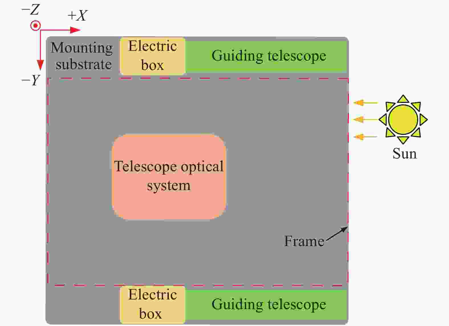
Figure 1. Schematic diagram of the overall structure of the space solar telescope
由于空间环境具有冷黑背景、极低温与极高温转变、单粒子效应、原子氧腐蚀等因素[2],一方面,该空间太阳望远镜在轨运行于720 km的太阳同步轨道,将面临空间低温热沉、太阳直射、地球红外辐射和地球阳光反照等多种复杂热环境[3];另一方面,空间向阳面与背阴面热流相差很大,容易造成望远镜温度分布不均匀[4],从而影响太阳望远镜的成像质量。因此,为保证该空间太阳望远镜在太阳同步轨道上的正常运行,降低温度对光学系统成像质量的影响,该空间太阳望远镜热控系统的合理可靠和有效准确是科学仪器设计的一个重要任务。
美国NASA在2010年发射的太阳动力学天文台(Solar Dynamics Observatory, SDO)搭载日震和磁场成像仪(Helioseismic and Magnetic Imager, HMI)对太阳内部动力学进行观测研究。望远镜主体框架表面包覆由涤纶网和聚酰亚胺膜组成的多层隔热组件,电控箱位于主体框架内部,受外热流的影响很小,需通过主动热控的方式保证电箱的温度控制在24 ℃,对日追踪光学系统前增设50Å (1Å=10−10 m)带通滤光片,反射绝大部分太阳直射能量。光学系统采用被动热控的方式进行热设计,在主镜与次镜间使用低热膨胀系数的碳纤维管连接,降低光学系统间温度的传导所引起的热变形。光学系统的安装边缘与外管壁接触,外管壁作为辐射器可将光学系统的热量直接辐射至冷黑空间,从而降低光学系统表面的温度,使光学系统的整体温度控制在24 ℃左右[5-6]。
2017年我国发射的某太阳极轨射电望远镜由卫星本体和8个天线单元组成,使用时钟扫描原理进行科学探测,用于连续跟踪监测日冕物质抛射事件从太阳表面到地球轨道处的传播和演化。整星采用主动热控(电加热器)与被动热控(散热面、热管、热控涂层、隔热安装)相结合的方式保证望远镜光学系统及CCD (Charge Coupled Device)探测器组件的正常工作。其中卫星本体框架外表面包覆多层隔热组件进行保温,组件最外面一层为Beta布,保证热控材料免受原子氧的腐蚀。在电控箱及望远镜关键部件上设置主动加热区来保证整星在极低温工况下的温度水平,散热面设置在外热流影响较小的卫星本体一侧,保证了望远镜在轨运行时的正常工作[7-8]。
文中以我国某空间太阳望远镜为研究对象,结合轨道热环境和自身热特性进行热控方案的设计与有限元仿真分析,研究本体框架与导行镜在极端工况条件下对复杂热环境的适应能力,并进行热平衡试验,验证热设计的正确性,获得关键零部件的温度分布数据。
-
该空间太阳望远镜的温度适应范围很大,依据结构需求,卫星在轨运行期间,望远镜各组件热控指标如表1所示。
Component Operating temperature/℃ Thermal control index/℃ Frame 19-25 22±1 Guiding telescope 19-25 22±1 Table 1. Thermal control index of each component of space solar telescope
-
空间热环境:该空间太阳望远镜与卫星平台隔热安装,安装脚为钛合金材料,在望远镜与卫星平台间用10 mm厚聚酰亚胺隔热垫,并使用钛合金螺钉联接,卫星安装面的温度范围为(22±5) ℃;望远镜还受到太阳直射、地球红外辐射及地球反照等空间外热流的影响。
内部热源:导行镜电箱2.4 W。
-
空间太阳望远镜本体框架与导行镜热控系统组成如图2所示。热控系统主要由热控涂层、隔热材料、导热填料、测温传感器、加热器等组成。

Figure 2. Thermal control system composition diagram
(1)隔热材料
1) 多层隔热材料:空间太阳望远镜本体框架与导行镜外表面包覆20单元多层隔热组件,每单元多层隔热组件由一层双面镀铝聚酯薄膜和一层涤纶网构成,多层隔热组件面膜为F46膜。多层隔热组件采用尼龙搭扣固定,尼龙搭扣的软面缝于多层隔热组件上,尼龙搭扣的硬面采用GD414C单组分室温硫化硅橡胶固定于底材上。F46膜表面红外发射率约为0.69,初期太阳吸收比为0.13,末期太阳吸收比为0.4;
2) 隔热垫:根据使用需求,隔热垫采用聚酰亚胺材料;
3) 联接件:根据使用需求,螺栓联接材料使用钛合金。
(2)热控涂层
黑色阳极氧化是在金属的表面经氧化处理形成致密而稳定的氧化膜,表面发射率≥0.85,可有效增强辐射换热,提高温度均匀性。
(3)导热填料
用于降低接触表面间的接触热阻而填加在接触表面间的易变形导热材料,主要采用了导热脂和GD414C单组分室温硫化硅橡胶。
(4)测控温传感器
热敏电阻:空间太阳望远镜本体框架与导行镜测温传感器采用MF501型热敏电阻闭环控制,互换精度为1% (±0.3 ℃),常用测温范围为−40~+70 ℃。
(5)电加热器
主动温控的电加热器采用125型聚酰亚胺薄膜型电加热器,通过GD414C单组分室温硫化硅橡胶粘贴。加热器采用PI闭环控温,最高工作温度可达150 ℃。
-
安装基板和框架除电箱安装面外,其余表面均包覆多层隔热组件[9-10],采用辐射散热的方式将主体框架吸收的热量排散至冷黑空间。为提高安装基板和框架的温度均匀性,所有部件表面均采用黑色阳极氧化处理。安装基板和框架的主动控温回路选用热敏电阻闭环控制,热敏电阻控温目标在轨可调。根据温度分布以及工作模式需要,将安装基板和框架主动控温回路分为6个加热回路,主体框架实施状态示意图如图3所示。

Figure 3. Schematic diagram of implementation state of frame
-
导行镜直接暴露于冷黑空间对日追踪定向,因此除安装面外,其余表面均包覆多层隔热组件,且导热安装在安装基板,通过传导和辐射换热的方式将热量排散至冷黑空间,镜筒前设置滤光片反射太阳直射的能量,避免导行镜温度过高发生热变形影响光学成像。因此,为提高导行镜镜筒的温度均匀性,镜筒内表面采用黑色阳极氧化处理,同时为保证导行镜在轨低温状态下满足工作目标的温度指标和储存状态时保证组件生存,导行镜的主动控温回路选用热敏电阻闭环控制,主动加热的位置布置于导行镜圆周方向的表面,根据不同的工况,热敏电阻设置控温目标(22±1) ℃,热敏电阻控温目标在轨可调,导行镜散热路径如图4所示。

Figure 4. Guide telescope cooling path diagram
-
此节以建立数学热分析理论模型为基础,在卫星飞行姿态及轨道参数、内热源输入、外部温度边界约束等条件下,分析并计算空间太阳望远镜本体框架和导行镜在空间环境中处于高低温观测模式下的温度分布情况,确定本体框架与导行镜在该工况模式下是否满足对应的热控指标。对空间太阳望远镜本体框架和导行镜建立有限元网络模型,具体步骤如下[11-12]:
(1)瞬态热传导微分方程
对于常物性,瞬态的温度场控制方程:
式中:
$\;\rho $ 为材料密度;$c$ 为材料比热容;$t$ 为时间;$k$ 为材料的热导率;$\varPhi $ 为组件内热源。经过有限元空间离散后,瞬态热传导方程为:式中:
${{C}}$ 为比热容矩阵;${{K}}$ 为热传导矩阵;$\dfrac{{\partial T}}{{\partial t}}$ 为节点温度对时间的导数矩阵;${{P}}$ 为温度载荷矩阵。对公式(2)进行向后差分迭代可计算出节点温度矩阵${{T}}$ 。(2)边界条件
初始温度条件和热边界条件为:
式中:
${{{T}}_{{0}}}$ 为初始时刻的温度值;${{{T}}_{{W}}}$ 为给定边界条件温度值;${{{T}}_{{E}}}$ 为环境温度值;${{{S}}_{{C}}}$ 表示热边界;${{{S}}_\varepsilon }$ 表示辐射边界;n为边界法线方向;q为流过组件表面的热流强度;${\sigma _\varepsilon }$ 为Stefan-Boltzmann常数;$\varepsilon $ 为组件表面的发射率。综上,依据模型上划分的每一个单元、节点及耦合关系,可由公式(1) ~ (6)的方程,根据卫星飞行姿态及轨道参数、内热源输入、外部温度边界约束、运行工况等条件利用有限元法的思想联立求解温度场,得到各特征点的温度数据。
-
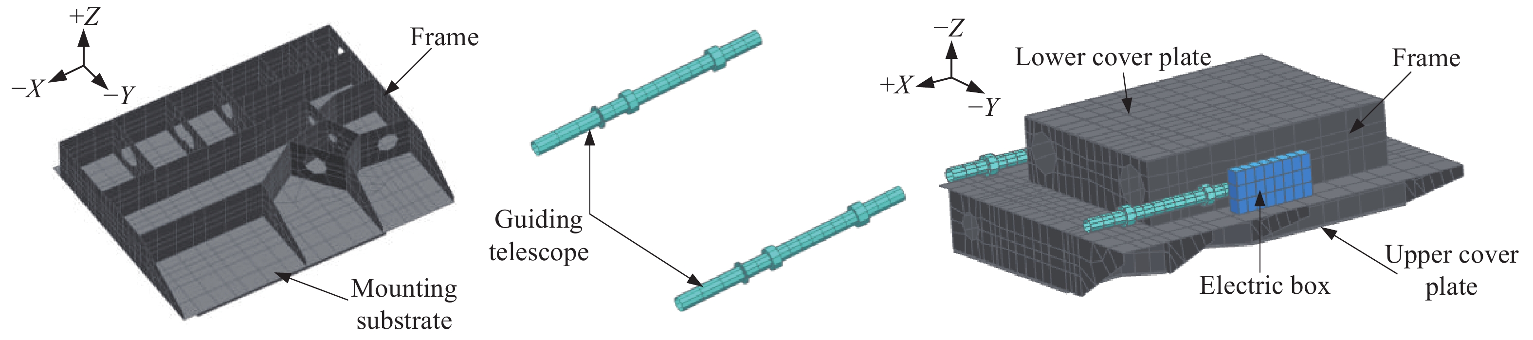
为了验证该空间太阳望远镜本体框架与导行镜热设计的正确性和有效性,采用有限元热分析软件建立了组件的热分析模型[13-14],如图5所示,共建立2622个单元,2780个节点,26组热耦合。卫星飞行于720 km的太阳同步轨道,在不做任何热控处理表面(干接触)接触导热系数取200 W/(m2·K),涂抹导热脂的表面接触导热系数取1200 W/(m2·K),多层与本体间接触导热系数取0.1 W/(m2·K)。分析计算工况的参数设置如表2所示,选取高、低温两种工况进行在轨热分析计算,检验在这两种工况条件下本体框架及导行镜的温度是否满足相应的热控指标,其中各组件材料参数如表3所示。

Figure 5. Finite element thermal analysis model
Operating mode Working state Parameter setting High temperature Guide mirror operation (Balanced condition) a) The telescope is in a high temperature external heat flow, the solar constant is 1412 W/m2;
b) Thermal control coating takes end-of-life value;
c) The 87° light angle guide is oriented to the sun.Low temperature Guide mirror operation (Balanced condition) a) The telescope is in a high temperature external heat flow, the solar constant is 1322 W/m2;
b) Thermal control coating takes initial value of life;
c) The 57° light angle guide is oriented to the sun.Table 2. Thermal analysis conditions and parameter settings
Component Material Density/kg·m−3 Specific heat capacity/ J·(kg·℃)−1 Thermal conductivity/W·(m· ℃)−1 Frame Aluminium alloy 7A09 2800 921 154 Guiding telescope Aluminium alloy 2A12 2800 920 121 Table 3. Main parameters of component materials
-
为获取空间太阳望远镜在轨热边界条件下各组件温度分布数据和对空间太阳望远镜的热设计进行验证,考核热控系统的能力,进行了组件试验件的热平衡试验。
为明确各组件设计状态与热平衡试验状态的材料、测试元器件、导热或隔热措施等是否满足一致性,本体框架与导行镜组件设计状态与试验状态分析对比如表4所示。其中,测温传感器的使用有所不同,设计状态采用MF501型热敏电阻,考虑到热敏电阻对温度的适应能力强,测温范围广,互换精度高,但MF501型热敏电阻成本较高,一般用于在轨温度遥测;而试验状态使用了热电偶,材料为铜+康铜,直接与被测对象接触,通过测量铜和康铜两极的电势来测量所在位置的温度,不受中间介质影响,其装配简单,成本低,适用于地面多点测温,以获取温度分布数据进行综合分析。
Num. Component name Design status Test status Consistency analysis 1 Frame Aluminium alloy 7A09 Aluminium alloy 7A09 Accordance 2 Guiding telescope Aluminium alloy 2A12 Aluminium alloy 2A12 Accordance 3 Temperature measurement sensor Thermistor Thermocouple Meet the test requirements 4 Thermal conductive filler Thermal grease Thermal grease Accordance 5 Heat insulation material 20-unit multilayer insulation assembly
(Mask is F46 film)20-unit multilayer insulation assembly
(Mask is F46 film)Accordance 6 Heater 125 type polyimide film heater 125 type polyimide film heater Accordance Table 4. Analysis and comparison of design state and test state of frame and guiding telescope components
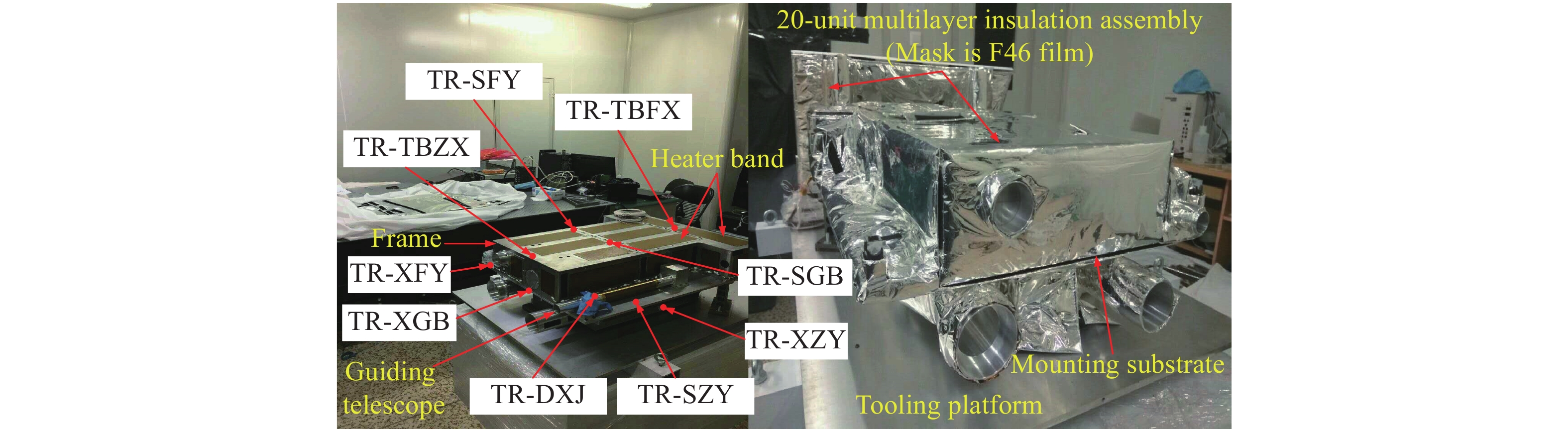
试验平台置于空间环境模拟器(简称真空罐,100 K热沉,真空罐内压力不高于1.3×10⁻³ Pa)中模拟空间4 K冷黑环境。4 K冷黑环境的热辐射能量非常小,大约为5×10⁻⁶ W/m2,对航天器的热控来说可以不予考虑,而地面试验采用液氮制冷并抽真空,相当于黑体辐射的热流为5 W/m2,对太阳常数与地球红外辐射来说,其占比分别为0.14%和1%左右,从热控设计的角度看,地面试验是可行的。本体框架与导行镜按照表4所给的试验状态进行热平衡试验。本体框架与导行镜的外热流模拟采用在试验件表面粘贴聚酰亚胺加热片的方式来模拟吸收外热流,其中外热流的功率按照瞬态模拟,本体框架外热流主要集中在上盖板处,高温工况下上盖板到达外热流为96.71 W/m2,上盖板的面积为0.581 m2,表面发射率为0.69,因此,上盖板在高温工况下的吸收外热流模拟功耗为38.8 W;低温工况下上盖板到达外热流为70.31 W/m2,则低温工况下吸收外热流模拟功耗为27.8 W,其余各面的外热流很小可以忽略不计。本体框架设置主动热控,保证本体温度在高低温工况下满足热控指标,其加热片工作功耗、电压及回路总阻值如表5所示。为保证本体框架与导行镜试验件包覆表面的发射率与实际状态一致,将模拟吸收外热流的加热片粘贴在F46膜内侧。加热片通过PI闭环控温,根据给定的目标温度值与实际测得温度值构成温度控制偏差,将偏差的比例和积分通过线性组合构成温度控制量,从而对加热片进行闭环控制。热平衡试验装置及平台如图6所示,试验中,采取热电偶多位置取点测温的方式,获取各组件的温度分布数据,测控温位置及代号如表6所示。
Position Working power/W Working voltage/V Total circuit resistance/Ω Upper cover plate 10 30 90 Lower cover plate 7.77 30 115.8 Upper of mounting substrate −Y 7 30 128.6 Upper of mounting substrate +Y 7 30 128.6 Lower of mounting substrate −Y 7.25 30 124.1 Lower of mounting substrate +Y 6.95 30 129.5 Table 5. Operating power, voltage and total circuit resistance of the heater of the frame
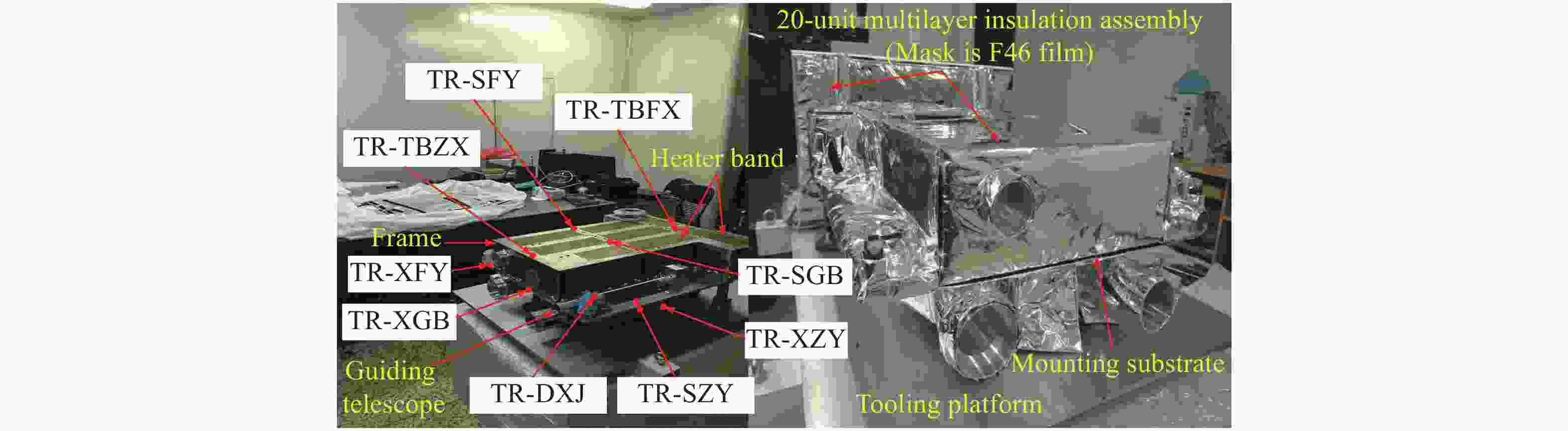
Figure 6. Thermal equilibrium test device and platform
No. Position Sensor code 1 Frame +X TR-TBZX 2 Frame −X TR-TBFX 3 Upper cover plate TR-SGB 4 Lower cover plate TR-XGB 5 Upper of mounting substrate −Y TR-SFY 6 Upper of mounting substrate +Y TR-SZY 7 Lower of mounting substrate −Y TR-XFY 8 Lower of mounting substrate +Y TR-XZY 9 Guiding telescope TR-DXJ Table 6. Test location and code for temperature control
-
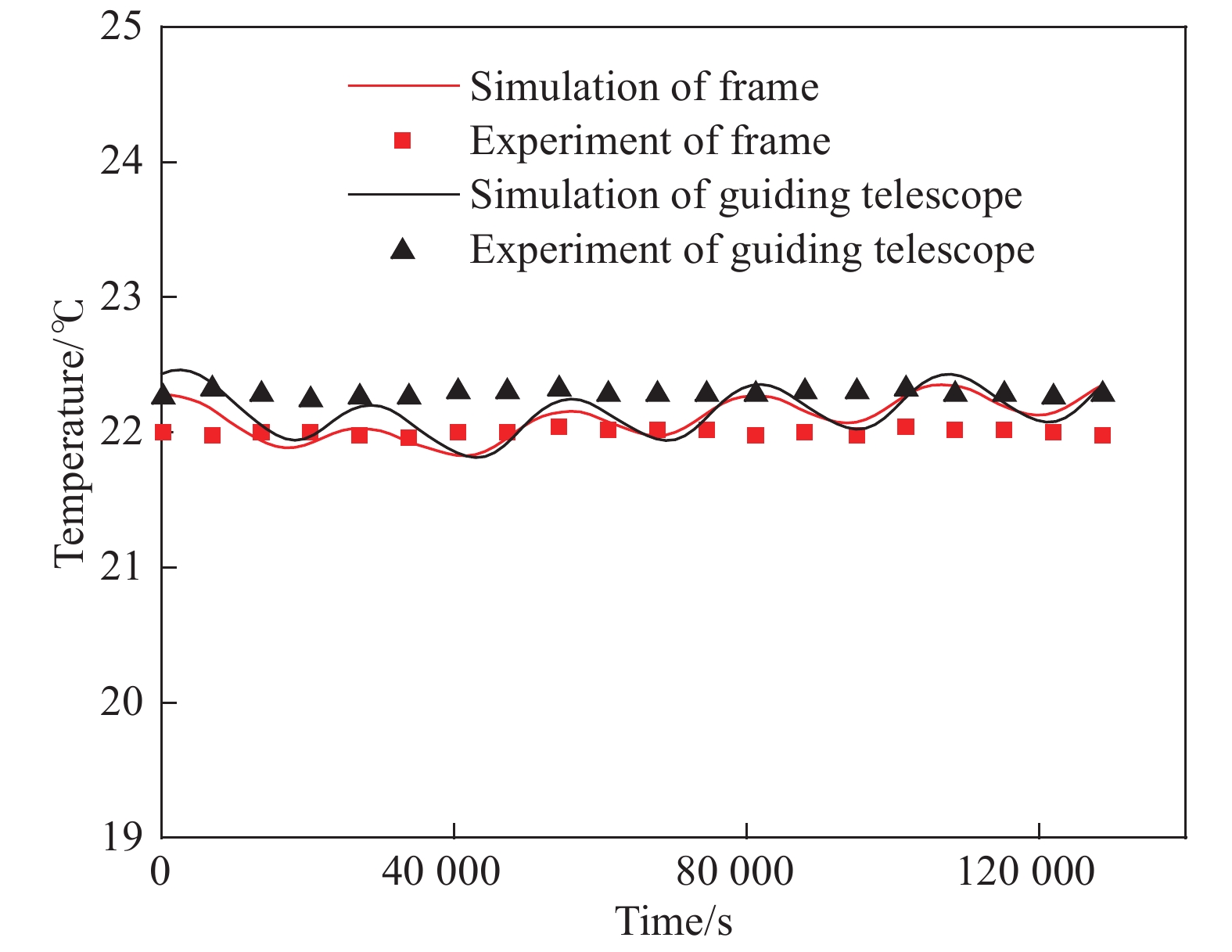
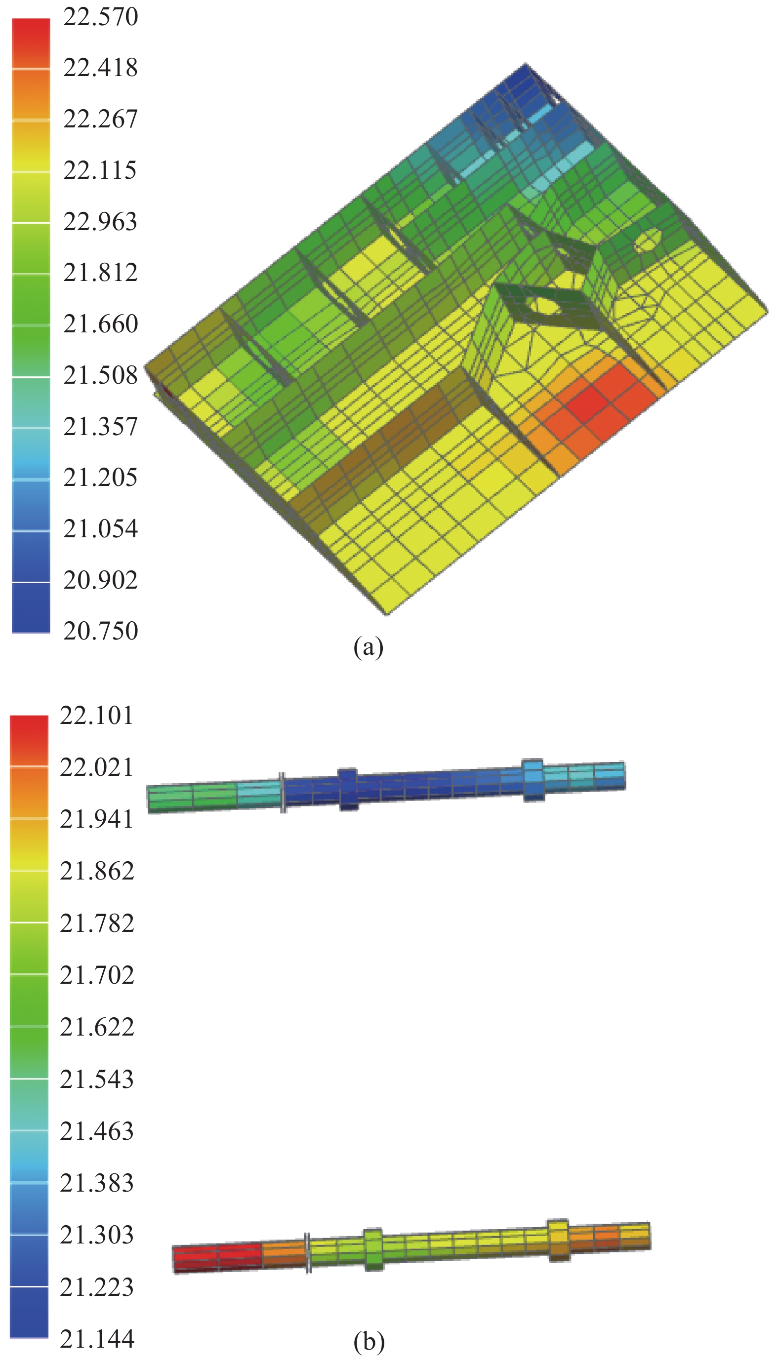
高温工况下有限元网络模型仿真结果显示,本体框架平均温度为22.3 ℃,导行镜平均温度为22.3 ℃,热分析云图如图7所示;热平衡试验中本体框架温度为22.0 ℃,导行镜温度为22.3 ℃。高温工况下仿真与试验对比曲线如图8所示,高温工况下主动闭环加热区位置及平均功耗统计如表7所示。
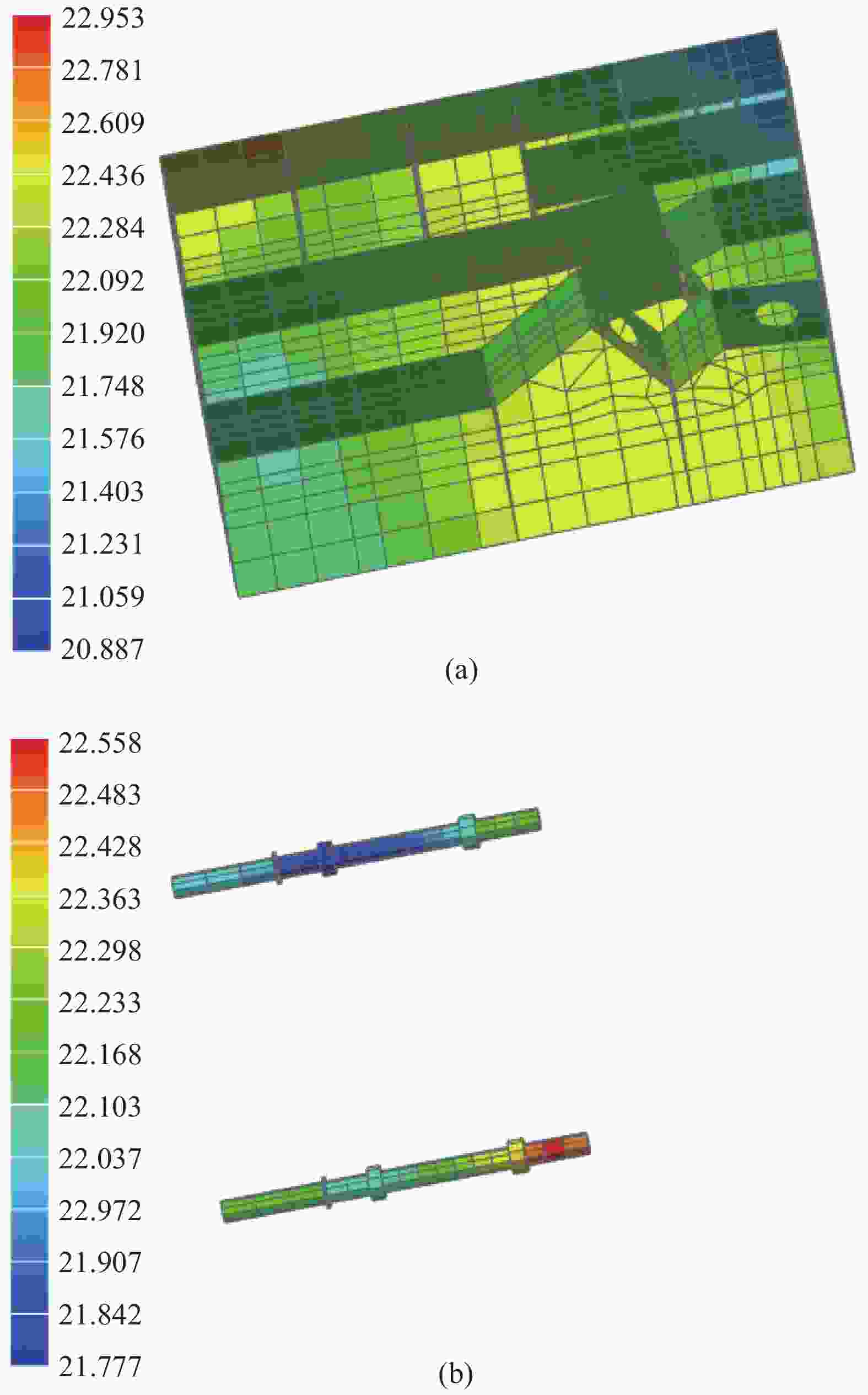
Figure 7. Thermal analysis cloud of frame (a) and guide telescope (b) under high temperature conditions

Figure 8. Comparison curve between simulation and test under high temperature conditions
No. Heating zone Finite element simulation analysis of average power consumption/W Thermal equilibrium test average power consumption/W 1 Upper cover plate 1.0 1.1 2 Lower cover plate 0 0 3 Upper of mounting substrate -Y 6.3 6.7 4 Upper of mounting substrate +Y 6.1 6.5 5 Lower of mounting substrate -Y 3.6 3.8 6 Lower of mounting substrate +Y 3.8 4.0 7 Guiding telescope 3.2 3.1 8 Summation 24 25.2 Table 7. Position of heating zone at high temperature and average heating power consumption
-
低温工况下有限元网络模型仿真结果显示,本体框架平均温度为22.3 ℃,导行镜平均温度为22.2 ℃,热分析云图如图9所示;热平衡试验中本体框架温度为22.0 ℃,导行镜温度为22.0 ℃。低温工况下仿真与试验对比曲线如图10所示,低温工况下主动闭环加热区位置及平均功耗统计如表8所示。

Figure 9. Thermal analysis cloud of frame (a) and guide telescope (b) under low temperature conditions

Figure 10. Comparison curve between simulation and test under low temperature conditions
No. Heating zone Finite element simulation analysis of average power consumption/W Thermal equilibrium test average power consumption/W 1 Upper cover plate 1.0 1.1 2 Lower cover plate 0 0 3 Upper of mounting substrate -Y 7.3 6.7 4 Upper of mounting substrate +Y 7.1 6.6 5 Lower of mounting substrate -Y 3.6 3.9 6 Lower of mounting substrate +Y 3.8 3.7 7 Guiding telescope 3.2 3.2 8 Summation 26 25.2 Table 8. Position of heating zone at low temperature and average heating power consumption
因此,从高低温工况下有限元仿真分析与热平衡试验对比曲线可知:本体框架与导行镜各组件的温度呈均匀分布,均满足(22±1) ℃的热控指标,有限元仿真与热平衡试验各组件温差均<1 ℃。高温工况下有限元仿真分析本体框架与导行镜平均功耗为24 W,热平衡试验本体框架与导行镜平均功耗为25.2 W,功耗差为1.2 W;低温工况下有限元仿真分析本体框架与导行镜平均功耗为26 W,热平衡试验本体框架与导行镜平均功耗为25.2 W,功耗差为0.8 W,其中下盖板的功耗消耗很小,可取消该加热区,不会对其余组件产生温度波动。此时高低温工况下有限元仿真与热平衡试验本体与导行镜的平均功耗相差不大,是由于这两部分组件表面均包覆了多层隔热组件,低温工况时保温性能好,不需要更多的功耗对组件加热即可满足需求。这里需指出,当有限元分析计算精度超过某一限度时,无论提高多少的精度,此时计算结果已与网格多少无关,文中的有限元分析计算已经做到网格无关性,另外试验数据的误差来源最主要是热偶与测温采集设备的测量误差,试验测量的总误差<0.5 ℃,属于很小系统误差,满足试验要求。综上所述,本体框架、导行镜在有限元网络模型仿真结果与热平衡试验结果基本一致,各组件温度在高低温工况模式下稳定且满足热控指标的要求,因此各组件热设计是可行的,热分析模型是正确有效的,既能满足理论上的热控要求,也能在试验阶段保持很好的温度稳定性。
试验是基于热控模拟件的地面热平衡试验,并且其内热源是通过加热片进行模拟,与产品正样阶段的真实组件有差异,导致模拟件与正样件热平衡试验结果会有一定的误差。后续将通过正样件的热平衡试验与在轨仿真结果进行对比分析,进一步优化框架与导行镜的热控设计,满足热控指标的同时,提高可靠性。
-
通过研究空间太阳望远镜本体框架与导行镜的热设计,并进行有限元仿真分析与热平衡试验,得出以下结论:
(1)本体框架和导行镜在高低温工况下各组件温度均满足(22±1) ℃的热控要求;
(2)主动热控加热区布置合理,各组件温度均匀性满足热控要求;
(3)本体框架与导行镜有限元仿真与热平衡试验在高低温工况下功耗差均很小,高温工况下的功耗差为1.2 W,低温工况下的功耗差为0.8 W;
(4)有限元仿真与热平衡试验在同一工况下各组件的温度均匀分布,且波动均小于1 ℃,验证了热设计的正确性,实现了复杂工作机制下对日追踪光学系统和本体的高精度控温,可为深空太阳望远镜在轨稳定运行及热设计优化提供理论支撑。
Thermal design of space solar telescope
doi: 10.3788/IRLA20200294
- Received Date: 2020-08-04
- Rev Recd Date: 2020-10-29
- Available Online: 2021-05-12
- Publish Date: 2021-04-30
-
Key words:
- thermal design /
- finite element simulation analysis /
- thermal equilibrium test /
- thermal power consumption /
- space solar telescope
Abstract: Aiming at the thermal characteristics of space solar telescope with long working time and harsh working environment, the thermal design of space solar telescope frame and guiding telescope under extreme working conditions was carried out. Through the finite element simulation analysis and thermal equilibrium test under high and low temperature conditions, the thermal analysis and thermal equilibrium test results of the frame and the guiding telescope were compared. The temperature was controlled at 22 °C, and the temperature fluctuation of each component under the same condition was less than 1 °C, which verified the correctness of the thermal control design. At the same time, the power difference between the finite element simulation of the frame and the guiding telescope and the thermal equilibrium test was 1.2 W at high temperature and 0.8 W at low temperature. The simulation analysis is consistent with the thermal equilibrium test, and the analysis is correct and effective, which ensures the normal operation of the telescope under complex working conditions. It provides a theoretical basis for improving the reliability and thermal design optimization of the space solar telescope module and solar tracking optical system.


 DownLoad: