


-
快速反射镜作为光发射端与接收端之间控制光束指向的精密光学仪器,集光、机、电技术于一身,具有系统带宽宽、响应速度快、定位精度高、位置分辨率高等优点,通常与大惯量转台一起构成复合轴系统,广泛应用于激光跟瞄、激光通信、自适应光学等高精密光学系统中。MIT学者经过长期的研究发现,具有高带宽的快速反射镜可以降低对载荷的复杂程度、成本和质量的要求,提高激光通信的数据传输能力[1]。
为了提高快速反射镜系统的带宽和响应速度、减少摩擦力对系统闭环特性的影响,负载支撑方式通常采用无摩擦、无空回、无需润滑等优点的柔性支撑方式,柔性支撑的结构形式包括柔性铰链、柔性平板和柔性轴等。与柔性平板和柔性轴相比,柔性铰链结构形式简单、转动中心具有很好的稳定性等优点,常用于精度高的场合。
在设计时,虽然对柔性支承细颈处的形位公差进行了严格的控制,对四个柔顺单元的空间关系做出了明确的要求,但柔顺单元采用慢走丝的加工工艺,细颈最薄处只有0.9 mm,在加工过程中难免引入误差。同时,快速反射镜伺服机构采用人工装配,在装配过程中也会引入误差[2-6]。
由于加工引入的误差包括:
(1)机械加工后细径最薄处的厚度偏离设计值,导致刚度与设计值不符;
(2)两组柔顺单元的旋转轴线非正交。
由于人工装配引入的误差包括:
(1)柔性支承的坐标轴系与驱动轴系α-O-β不重合;
(2)柔性支承的坐标轴系与系统轴系X-O-Y之间的夹角不等于45°;
(3)反射镜质心偏离几何中心,基座角运动会形成不平衡干扰力矩,不平衡干扰力矩的存在进一步降低系统的跟踪精度。
另外,在长期储存及长时间的工作过程中,柔性铰链的弹性系数
${K_s}$ 、驱动轴系α-O-β与系统轴系X-O-Y之间的耦合矩阵${C_{XY{\rm{ - }}\alpha \beta }}$ 等参数与设计参数相比可能会发生偏移,这些参数发生偏移将对系统的控制精度产生影响。为实现快速反射镜系统的高精度控制,需要辨识伺服机构参数,为自适应控制提供数据支撑。文中研究多输入多输出线性系统开环参数辨识方法,讨论多输入多输出线性系统参数开环辨识流程、脉冲传递函数以及耦合矩阵的获取方法等,通过仿真验证辨识流程和方法的可行性。并以通光口径φ100 mm、行程±10 mrad、工作带宽大于200 Hz的快速反射镜伺服机构作为研究对象,对辨识方法进行实验验证。
-
文中在参考文献[7]的基础上开展伺服机构模型参数的辨识。
由参考文献[7]可知,伺服机构以两轴柔性铰链作为支撑,选用音圈电机作为驱动器、电涡流传感器作为测量元件。为缩小伺服机构的体积,同时提高传感器的测量精度,将音圈电机和位置传感器交错均布在以柔性支撑为圆心的圆周上。快速反射镜结构简图如图1所示。

Figure 1. Structure of fast steering mirror servo mechanism
为了推导伺服机构的数学模型,建立了坐标系,称位置传感器所在的轴系为系统轴系X-O-Y,音圈电机所在的轴系为驱动轴系α-O-β,驱动轴系与系统轴系之间的关系如图2所示。

Figure 2. Relationship between system-axis and drive-axis
定义了系统轴系与驱动轴系之间的夹角,
${\theta _{{x}}}$ 表示驱动轴系α轴与系统轴系X轴之间的夹角,X轴绕O点逆时针转向α轴为正;${\theta _{{Y}}}$ 表示驱动轴系β轴与系统轴系Y轴之间的夹角,Y轴绕O点逆时针转向β轴为正。 -
在搭建伺服机构和建立双坐标系的基础上,推导了柔性支撑快速反射镜伺服机构的脉冲传递函数矩阵。
反射镜镜面转角
$\varPhi (k) = {\left[ {{\phi _x}(k){\phi _y}(k)} \right]^{\rm{T}}}$ 与控制输入$U(k) = {\left[ {{u_x}(k){u_y}(k)} \right]^{\rm{T}}}$ 之间的关系为:式中:
${G_{{{x}}\alpha }}({{\textit{z}}^{ - 1}})$ 、${G_{{{y}}\alpha }}({{\textit{z}}^{ - 1}})$ 、${G_{{{x}}\beta }}({{\textit{z}}^{ - 1}})$ 和${G_{{{y}}\beta }}({{\textit{z}}^{ - 1}})$ 表示通道X和通道Y之间的交叉耦合脉冲传递函数;${G_\alpha }({{\textit{z}}^{ - 1}})$ 、${G_\beta }({{\textit{z}}^{ - 1}})$ 表示驱动轴系α-O-β转动角度与控制电压之间的脉冲传递函数,有:式中:
$i = \alpha ,\beta $ ;${G_i}(s)$ —第i驱动轴传递函数;${J_i}$ —第i驱动轴的转动惯量,kg·m2;${k_{si}}$ —第i驱动轴柔性支撑弹性系数,N·m/rad;${k_{mi}}$ —第i驱动轴力矩系数,N·m/A。令
${C_{XY{\rm{ - }}\alpha \beta }} = \left[ {\begin{array}{*{20}{c}} {\cos {\theta _X}}&{ - \sin {\theta _Y}} \\ {\sin {\theta _X}}&{\cos {\theta _Y}} \end{array}} \right]$ ,称${C_{XY - \alpha \beta }}$ 为α-O-β轴系到X-O-Y轴系的耦合矩阵。将公式(2)代入公式(1)有:
-
所谓辅助变量法,就是通过选择辅助变量矩阵X,X满足以下条件:(1)
$\mathop {p\lim }\limits_{N \to \infty } {X^{\rm{T}}}e = 0$ ;(2)$\mathop {p\lim }\limits_{N \to \infty } {X^{\rm{T}}}\psi $ 正定,则称X中的元素为辅助变量。这就要求所选用的辅助变量尽可能地与噪声$n(k)$ 不相关、与有用信号相关。其最大特点是对噪声及其成形滤波器没有特殊的假设,噪声$n(k)$ 可以是任意的平稳有色噪声。辅助变量
${{X}}(k)$ 的选择有多种方式,如下:式中:
${n_a}$ 为多项式$A({{\textit{z}}^{ - 1}})$ 的阶次;${n_d}$ 为多项式$D({{\textit{z}}^{ - 1}})$ 的阶次。辅助变量最小二乘法的递推公式为:
式中:
$\psi (k)$ 为数据向量。且 -
快速反射镜伺服机构的脉冲传递函数是双输入双输出线性系统,输入与输出之间是紧耦合。为了实现快速反射镜自适应控制,伺服机构的参数辨识需要完成两方面的工作:一是伺服机构脉冲传递函数的辨识,获得伺服机构脉冲传递函数矩阵;二是对获得的脉冲传递函数进行矩阵分解,分别获取耦合矩阵和单输入单输出线性系统脉冲传递函数矩阵[8-11]。
-
伺服机构是双输入双输出线性系统,属于多输入多输出系统范畴。对于多输入多输出系统的参数估计方法通常有传递函数矩阵参数估计方法、Markov参数估计方法以及输入输出差分方程参数估计方法等,以上方法均需要进行大量的矩阵运算与逆运算,计算量大。
针对以上原因,文中采用多输入单输出系统相关-辅助变量最小二乘参数估计法(COR-IV),将多输入多输出(MIMO)线性系统分解为多个多输入单输出(MISO)线性系统,分别对每个MISO线性系统应用COR-IV进行参数估计,再根据线性系统的叠加原理获得整个系统的模型参数[12-13]。该方法的优点是不需要繁冗的矩阵运算和逆运算、计算量较小,并且对噪声模型不敏感。下面给出采用COR-IV获取伺服机构脉冲传递函数的具体实现方式[14-16]。
设带有噪声的伺服机构脉冲传递函数矩阵为:
将公式(6)中
${\phi _x}(k)$ 支路采用差分方程描述,有:令
${u_\beta }(k)$ =0,当该支路的输入为零时其输出为有色噪声${\nu _\beta }(k)$ ,将该噪声与输出噪声合并,同一视作有色噪声${\nu _{x\beta }}(k)$ ,公式(7)可改写为:上式两边乘以
${u_\alpha }(k - \tau )$ 、取均值并整理,写成最小二乘格式,有:式中:
$n(\tau )$ 表示相关函数用对应的估计值代替后所造成的误差与输入与噪声的互相关函数${A_{x\alpha }}({{\textit{z}}^{ - 1}})\cdot $ $ {R_{{\nu _{x\beta }}{u_\alpha }}}(\tau )$ 的和。选取辅助变量
${h^{\rm{*}}}(\tau )$ :按公式(11)递推计算参数矩阵
$\hat \theta (k)$ ,分别获得${\theta _{\alpha x}}$ 、${\theta _{\alpha y}}$ 、${\theta _{\beta x}}$ 和${\theta _{\beta y}}$ 的估计值${\hat \theta _{\alpha x}}$ 、${\hat \theta _{\alpha y}}$ 、${\hat \theta _{\beta x}}$ 和${\hat \theta _{\beta y}}$ ,其中${\hat \theta _{\alpha x}}$ 的递推公式如下:则辨识到的伺服机构脉冲传递函数矩阵为:
-
令
${\hat G_b}({{\textit{z}}^{ - 1}}) = {G_b}({{\textit{z}}^{ - 1}})$ ,脉冲传递函数矩阵各系数相等,建立零点多项式系数方程组和极点多项式系数方程组:解方程组得各系数为:
-
仿真实验采用的脉冲传递函数矩阵为:
为了使仿真更贴近真实环境,在输出信号上叠加通过白色噪声经过成型滤波器的方式生成的有色噪声信号。辨识实验的实验框图如图3所示。

Figure 3. Diagram for identification test
辨识实验流程如图4所示。

Figure 4. Flow chart for identification test
a1 a2 b0 b1 b2 Static gain True value −1.55 0.72 0.212 0.389 0.248 4.99 Estimation −1.540 0.712 0.220 0.395 0.253 5.05 Table 1. Simulation results of α-X channel parameter estimation
a1 a2 b0 b1 b2 Static gain True value −1.55 0.72 0.212 0.389 0.248 4.99 Estimation −1.540 0.712 0.220 0.395 0.253 5.05 Table 2. Simulation results of α-Y channel parameter estimation
a1 a2 b0 b1 b2 Static gain True value −1.50 0.71 −0.212 −0.318 −0.354 4.21 Estimation −1.520 0.727 −0.188 −0.285 −0.345 3.95 Table 3. Simulation results of β-X channel parameter estimation
a1 a2 b0 b1 b2 Static gain True value −1.50 0.71 0.212 0.318 0.354 4.21 Estimation −1.495 0.709 0.222 0.321 0.357 4.21 Table 4. Simulation results of β-Y channel parameter estimation

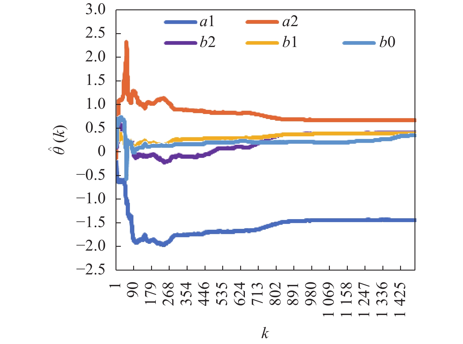
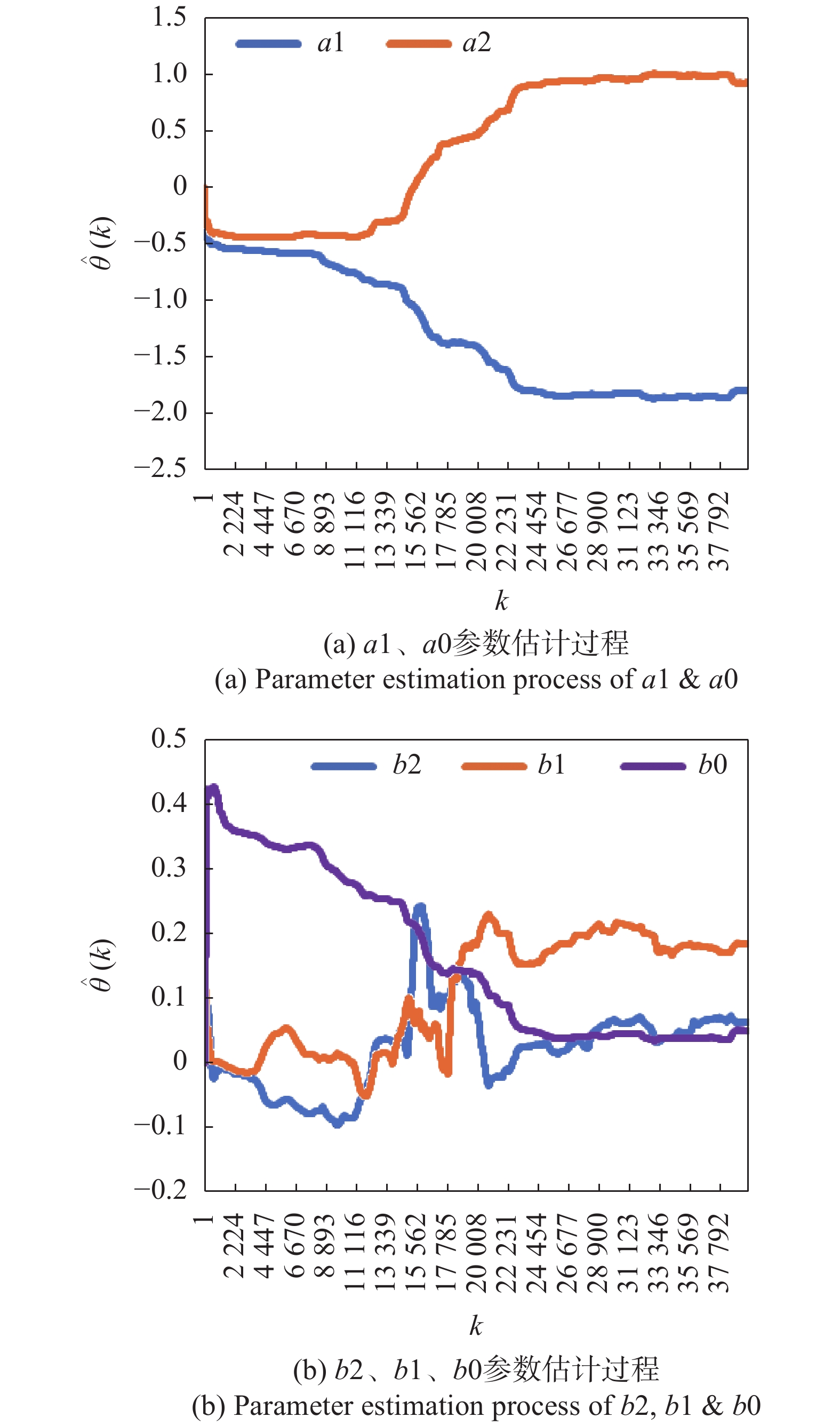
Figure 5. Simulation of parameter estimation process for α-X channel

Figure 6. Simulation of parameter estimation process for α-Y channel

Figure 7. Simulation of parameter estimation process for β-X channel

Figure 8. Simulation of parameter estimation process for β-Y channel
经计算获得的耦合矩阵和伺服机构脉冲传递函数系数见表5~表7。
cos(θX ) cos(θY) sin(θX) sin(θY) True value 0.707 0.707 0.707 0.707 Estimation 0.707 0.674 0.707 0.739 Table 5. Calculation results for decoupling matrix
a1 a2 b0 b1 b2 Static gain True value −1.550 0.720 0.300 0.550 0.350 4.99 Estimation −1.540 0.712 0.311 0.559 0.358 5.04 Table 6. Results of pulse transfer function parameters for α drive axis
a1 a2 b0 b1 b2 Static gain True value −1.500 0.710 0.300 0.450 0.500 4.21 Estimation −1.508 0.718 0.291 0.430 0.496 4.10 Table 7. Results of pulse transfer function parameters for β drive axis
-
辨识实验是在Matlab/dSPACE半实物仿真平台上进行的。伺服机构的输入信号通过半实物仿真平台D/A接口输出,并通过功率放大器放大后驱动伺服机构的两组音圈电机执行推拉工作;通过电涡流位置传感器测量并解算伺服机构反射镜转动的角度,并以模拟量的形式输出;通过A/D接口采集电涡流位置传感器输出的模拟信号以及D/A接口输出的输入信号,并转换成数字信号;Matlab对采集到的输入/输出信号利用m语言编程对脉冲传递函数进行辨识[17]。
-
为了验证辨识算法的有效性和准确性,针对自行研制的一款口径为100 mm、行程±10 mrad的双轴快速反射镜原理样机进行了脉冲传递函数辨识。快速反射镜伺服机构实物如图9所示。

Figure 9. Picture of FSM’s mechanism
-
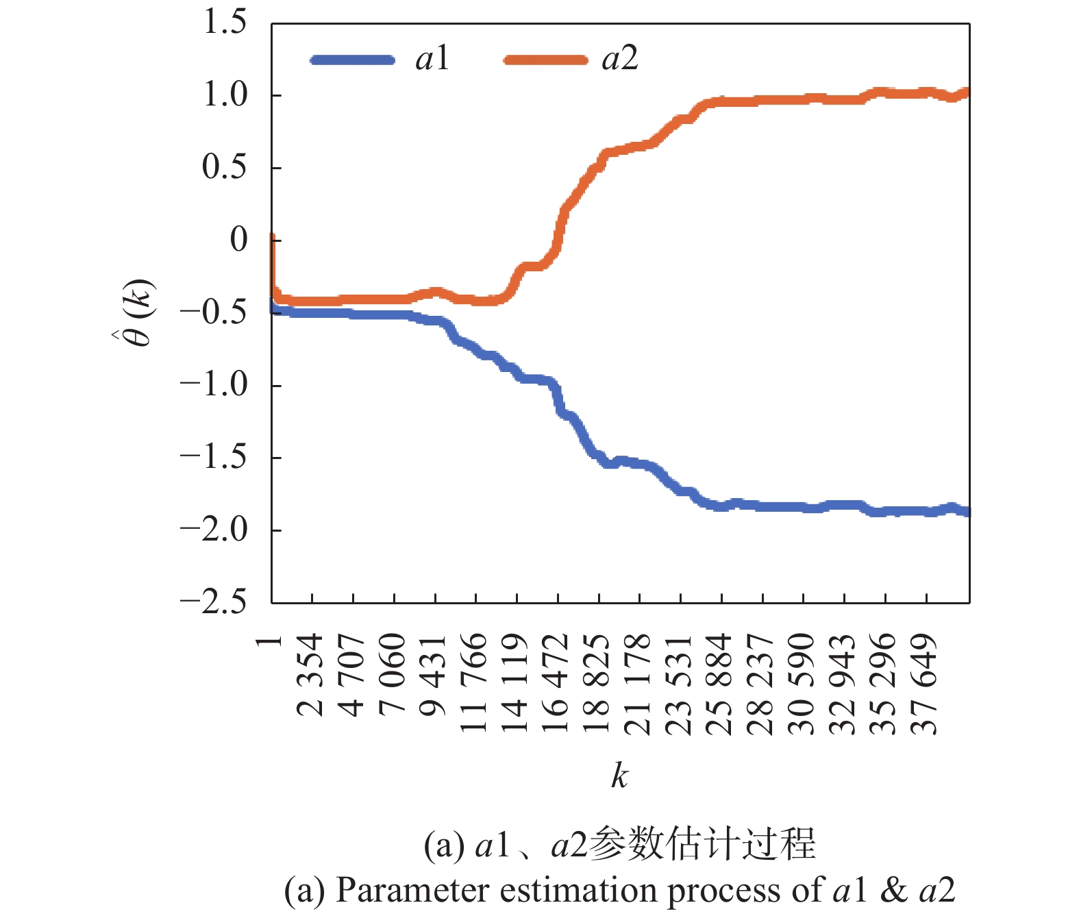
采用COR-IV对伺服机构脉冲传递函数进行辨识。采用M序列作为辨识用激励信号,首先利用相关—最小二乘估计算法启动运算,再采用COR-IV进行参数辨识。辨识结果见表8~表11。
Parameter a1 a2 b0 b1 b2 Result −1.8070 0.9440 −0.0300 −0.1360 −0.0340 Table 8. Parameter estimation results for α-X channel
Parameter a1 a2 b0 b1 b2 Result −1.8390 0.9650 0.0406 0.1739 0.0360 Table 9. Parameter estimation results for α-Y channel
Parameter a1 a2 b0 b1 b2 Result −1.8398 0.9939 0.0302 0.1583 0.0255 Table 10. Parameter estimation results for β-X channel
Parameter a1 a2 b0 b1 b2 Result −1.8259 0.9636 0.0434 0.2029 0.0618 Table 11. Parameter estimation results for β-Y channel

Figure 10. Parameter estimation process for α-X channel
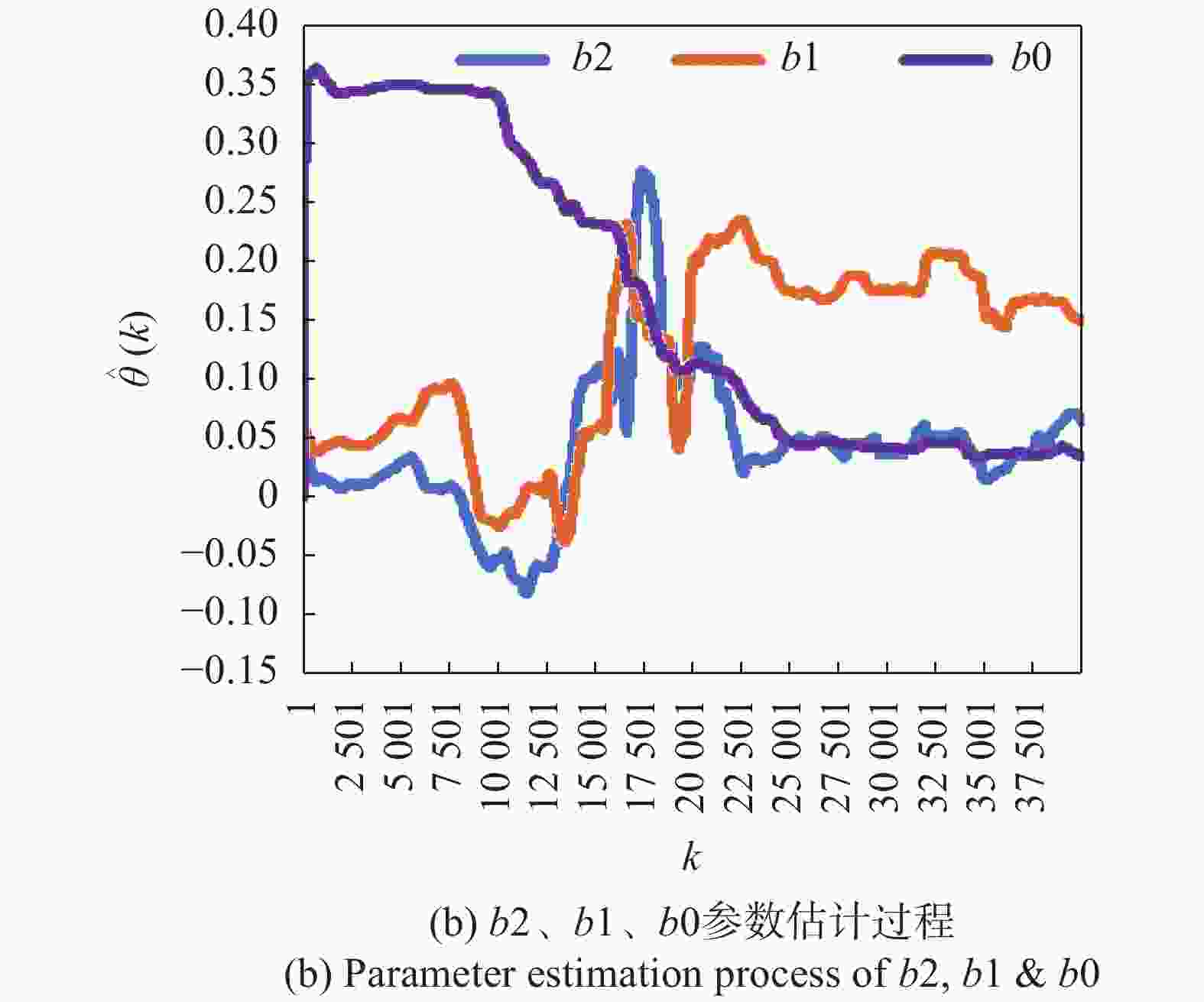
Figure 11. Parameter estimation process for α-Y channel

Figure 12. Parameter estimation process for β-X channel

Figure 13. Parameter estimation process for β-Y channel

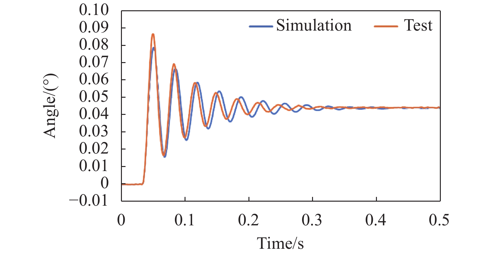
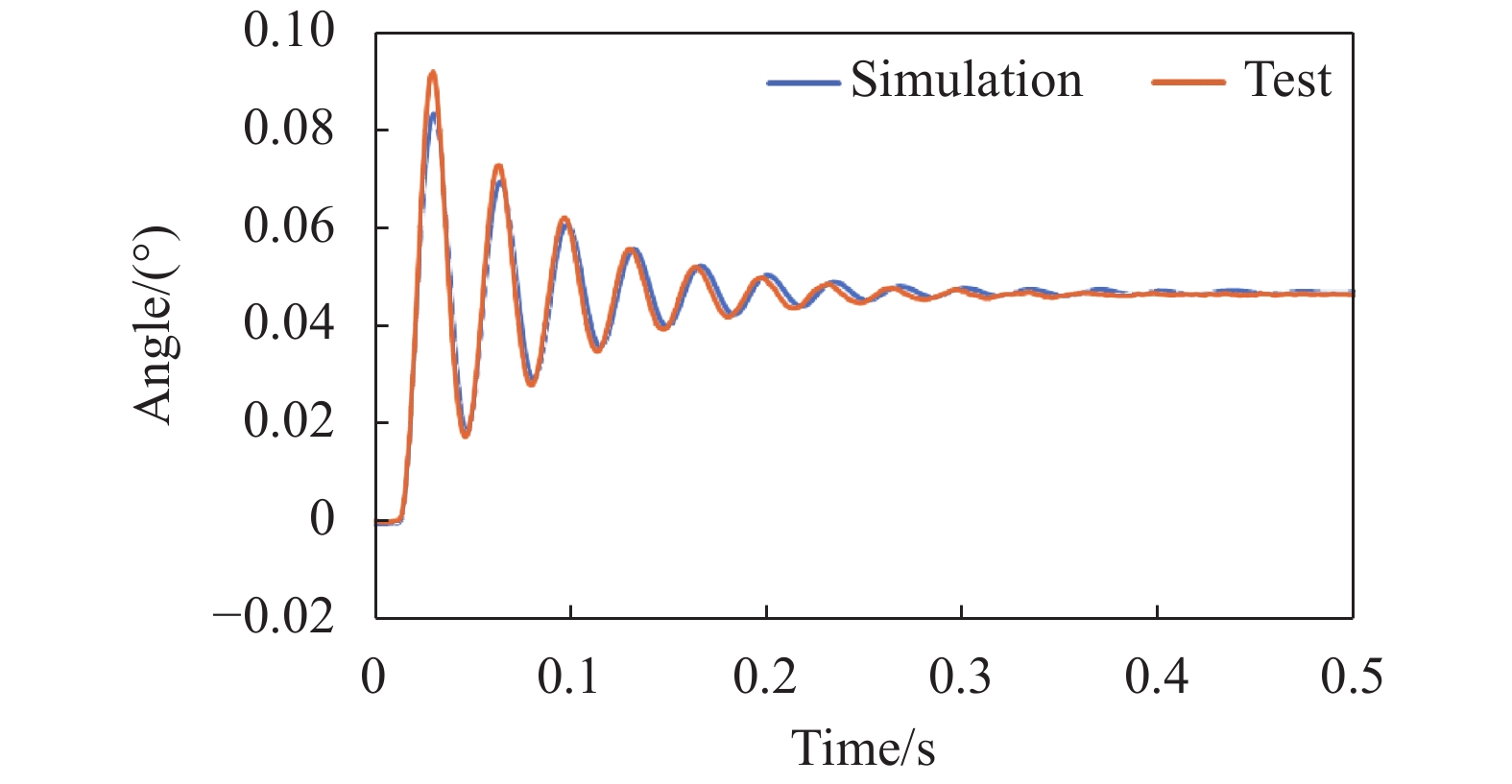
辨识结束后,将辨识结果代入到差分方程中,获取伺服机构的阶跃响应曲线,对辨识结果进行验证,响应曲线如图14~图17所示。

Figure 14. α-X channel step response comparation

Figure 15. α-Y channel step response comparation

Figure 16. β-X channel step response comparation

Figure 17. β-Y channel step response comparation
对图14~图17的数据从振荡次数、振荡频率、最大振荡幅值以及稳态误差等四方面进行对比分析,结果如下:
(1)从“振荡次数”方面进行对比,以进入5%误差带作为评判标准,实测结果在9~10次之间,仿真结果在10~11次之间;
(2)从“振荡频率”方面进行对比,实测结果在29.4~31.3 Hz之间,仿真结果在29.4~31.3 Hz之间;
(3)从“振荡幅值”方面进行对比,实测结果和仿真结果的误差在3%~10%范围,其中阶跃响应的第一个振荡环节误差最大;
(4)从“稳态误差”方面进行对比,四个通道的稳态误差均在5%以内。
上述对比表明,通过参数辨识获得的脉冲传递函数可反映被测伺服机构的特性。
-
文中从解决柔性支撑双轴快速反射镜伺服机构存在的问题角度出发,介绍了相关-辅助变量最小二乘算法和利用相关-辅助变量最小二乘算法获得被测对象参数的计算过程,通过数值仿真验证了计算过程的合理性和辨识算法的正确性。通过辨识快速反射镜原理样机的伺服机构脉冲传递函数零、极点多项式系数和伺服机构阶跃响应对比验证,证明了所提出的辨识算法有效、辨识精度在预期的范围内,可以为快速反射镜系统的自适应控制提供数据支撑。
Servo mechanism parameter identification of fast steering mirror based on flexible supports
doi: 10.3788/IRLA20200303
- Received Date: 2020-08-06
- Rev Recd Date: 2020-10-31
- Publish Date: 2021-05-21
-
Key words:
- system identification /
- transfer function /
- COS-IV /
- fast steering mirror /
- MIMO
Abstract: The problems of the two-axis fast steering mirror based on flexible support was put forward firstly, a servo mechanism structure of the two-axis fast steering mirror based on flexible support was introduced briefly, the pulse transfer function of the servo mechanism was established, the MIMO system parameter identification theory was discussed, and the method based on COR-IV method was analyzed. Based on the method, the identification method of servo mechanism based on flexible support for the two-axis fast steering mirror was proposed and simulated. The experiment for the identification of servo mechanism parameters was designed to verify the method and the experimental results were compared with theoretical calculations. The experimental results show that the MIMO system parameter identification algorithm based on the COR-IV method is effective, the identification accuracy is within the expected range, and the identification results can provide data support for the adaptive control of fast steering mirror.


 DownLoad: