


-
Optical measurement techniques have been employed in multiple areas, including industrial inspection, agricultural engineering, and intelligent manufacturing[1-3]. Recently, those techniques have been broadly applied in three-dimensional shape measurement. Among them, digital fringe projection (DFP) has drawn significant attention due to its speed, precision, and flexibility[4]. A projector can be employed to project fringe patterns onto the measured object, while the deformed patterns can be captured using the camera from the other orientation. Finally, a fringe analysis algorithm is applied for recovering the 3D shape of the measured objects. Fourier transform[5] and phase-shifting[6] are known as two fundamental fringe analysis techniques. The Fourier transform algorithm only utilizes one fringe pattern for phase retrieval; however, it is inefficient in the case of objects with sharp edges, sudden changes, and non-uniform surface reflectivity. The phase-shifting algorithm using multiple patterns is much more robust in 3D shape reconstruction. However, because both algorithms use an arctangent function, the obtained phase is wrapped in the range of
$( - \pi ,\pi ]$ with$2\pi $ discontinuities. Therefore, a phase unwrapping process is inevitably to retrieve the absolute phase.Many frequently used phase unwrapping operations are available, which can be broadly classified into spatial methods[7] and temporal methods[8]. In the spatial method, the
$2\pi $ discontinuities are removed without projecting any additional patterns, thus lacking of robustness to unwrap all pixels. Phase unwrapping operator per pixel in the temporal method improves its stability when measuring complex surfaces or isolated objects, though more than one pattern is required. Temporal methods mainly include multi-frequency [9-10], phase-coding[11-13] and Gray-code (GC)[14-15] etc., where GC method can robustly identify fringe order of the wrapped phase by projecting a set of binary GC patterns. However, because of the random noise and the defocus effect, the boundaries of two adjacent binary GC values are not sharply cut-off, leading to some errors in phase unwrapping. To overcome this challenge, Zhang et al.[15] developed a complementary GC approach to remove phase unwrapping errors at the cost of projecting and capturing an additional GC pattern. Yu et al.[16] proposed an approach to optimize the GC encoding period and phase-shifting fringe period to avoid incorrect code orders and decoding errors. With the development of binary defocusing techniques, a dynamic 3D shape measurement has now become possible. However, this technique has a drawback when objects are moving rapidly, and the motion-induced errors may cause phase wrapping failure. To this end, Wu et al.[17] combined the conventional spatial phase unwrapping method with the GC method to alleviate the phase unwrapping errors due to the motion. Wu et al.[18] proposed a cyclic complementary GC method based on the complementary GC method and a new cyclic coding strategy, which can effectively improve the measurement depth range and accuracy. Subsequently, the shifting GC coding strategy[19] is employed to reduce the phase unwrapping errors at the codewords edge and has been proven successful for high-speed dynamic 3D shape measurement. Although the GC method is widely used for phase unwrapping, it has its own drawbacks. For example, simultaneously performing a fast and accurate measurement remains challenging because multiple GC patterns need to be projected and captured. To this end, ternary GC[20] and quaternary GC[21] methods have been introduced to reduce the number of required GC patterns without sacrificing measuring accuracy. For fringe patterns with n periods, the ternary GC method requires${\log _3}n$ GC patterns, whereas the quaternary GC method requires${\log _4}n$ patterns.This paper developed an enhanced GC method based on the geometric constraint method. Three GC patterns with
$M$ cycles are used for phase unwrapping of$8M$ fringe periods, where the wrapped phase is firstly obtained with the phase-shifting algorithm, and a cyclic fringe order${K_V}$ with$M$ cycles is obtained from the three GC patterns. Then, the wrapped phase is unwrapped to a pseudo unwrapped phase using${K_V}$ . The pseudo unwrapped phase is further unwrapped to the absolute phase by considering the minimum phase map, obtained through the geometric constraint method[22]. The experiments clarify that the enhanced GC approach can reliably recover the 3D shape of measured objects.The rest of this paper is organized as the following: Section 1 introduces the principle of the presented approach. Section 2 provides the experiments to evaluate the accuracy of the presented approach. In Section 3, the study is summarized and concluded.
-
The phase-shifting algorithm has shown good performance in the field of optical metrology, owing to its no-contact feature, high accuracy, and high speed. Therefore, we use the three-step phase-shifting algorithm for phase recovery to evaluate the efficiency of the presented method. The fringe patterns can be mathematically defined in Eqs.(1)-(3):
where,
$I'(x,y)$ and$I''(x,y)$ represent the average intensity of the fringe imagen and the intensity modulation, respectively;$\phi (x,y)$ is the wrapped phase. Under the given${I_1}$ ,${I_2}$ and${I_3}$ , Eqs. (1)-(3) can be rewritten as:In the Eq.(6), the arctangent function used to calculate the wrapped phase ranges from
$ - \pi $ to$\pi $ with$2\pi $ discontinuities, and then the phase unwrapping procedure is needed. The unwrapped phase$\varPhi (x,y)$ can be calculated as Eq.(7):where,
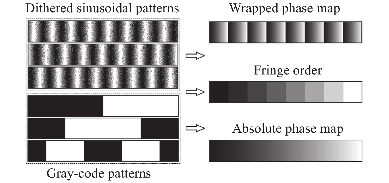
$K(x,y)$ indicates the fringe order of the wrapped phase. Subsequently, the GC method is used for phase unwrapping, and we use${K_{V}}$ to denote the fringe order calculated from GC patterns. For a wrapped phase with$n$ fringe periods, the conventional GC method requires${\log _2}n$ GC patterns to determine the fringe order. For example,$n$ is assumed as 8, and${\log _2}8 = 3$ GC patterns are required for phase unwrapping. And the average intensity of three phase-shifting patterns$I'(x,y)$ is chosen as the suitable threshold to binarize the GC patterns to obtain their codewords. Figure 1 illustrates the decoding process of the GC patterns, in which GC1, GC2, and GC3 are three GC patterns;$V$ is a decimal number, which can be computed as:
Figure 1. Obtainment of fringe order
${K_V}$ Finally, the fringe order
${K_V}$ can be determined on the basis of the one-to-one mapping relationship between$V$ and${K_V}$ .The binary dithering technique can provide successful image rendering and color reduction, and it operates successfully in generating high-quality sinusoidal patterns based on the binary defocusing technique[23]. Several dithering techniques have been presented, including simple thresholding, random dithering, Bayer-ordered dithering, and error diffusion dithering. Among them, the error-diffusion dithering has been widely employed, since it can better describe the primary image with the quantization errors being propagated[24]. Therefore, we apply this technique to generate sinusoidal fringes. Figure 2 shows the principle of conventional gray-code plus phase-shifting approach in summary.

Figure 2. Principle of conventional Gray-code plus phase-shifting approach
-
Researcher An[22] employed the geometric constraints of the DFP system to present a phase unwrapping method. The main idea is that a minimum phase map
${\varPhi _{{\rm{min}}}}$ can be created at the nearest plane${Z_{{\rm{min}}}}$ of the measurement volume. The wrapped phase$\phi $ can be converted to an unwrapped one pixel-by-pixel based on${\varPhi _{{\rm{min}}}}$ . Essentially,$K$ times$2\pi $ should be added to$\phi $ by comparing the difference between$\phi $ and${\varPhi _{{\rm{min}}}}$ . Figure 3 illustrates the principle of using${\varPhi _{{\rm{min}}}}$ to unwrap$\phi $ , which includes four$2\pi $ discontinuities: A, B, C, and D. The fringe order$K(x,y)$ can be obtained using the following equation:
Figure 3. Principle of using
${\varPhi _{{\rm{min}}}}$ to unwrap$\varPhi $ (${\varPhi _A}$ denotes the actual absolute phase, while$\varPhi $ denotes the recovered absolute phase)Here, function
$Ceil\left( {} \right)$ returns the closet upper integer value. According to Eq.(7), the absolute phase$\varPhi $ can be finally determined.From Fig.3, we can note that the maximum measurement depth ranging from the object to the plane
${Z_{{\rm{min}}}}$ , which can be handled by this method is$2\pi $ . It means that$\varPhi$ should satisfy the condition shown in the Eq.(10), otherwise phase unwrapping errors will be induced. As shown in Fig. 3 on the left of point C, the phase difference$\varPhi - {\varPhi _{\min }}$ is greater than 0 but less than$2\pi $ , and the wrapped phase$\phi $ is correctly unwrapped whereas on the right of point C, the phase difference is greater than$2\pi $ , and the wrapped phase$\phi $ is wrongly unwrapped. -
To reduce the number of required fringe patterns, an enhanced GC method based on geometric constraint method is proposed in this paper, where the GC patterns are designed to have several cycles. We use N to denote the number of the designed GC patterns. Obviously, N can be any integer, we take the N=3 as an example to describe the proposed method specifically in this paper. Figure 4 shows the sinusoidal and GC patterns with several cycles. The phase unwrapping method will be introduced in the following part.

Figure 4. Patterns of enhanced GC approach. (a)-(c) Phase-shifting dithered patterns; (d)-(f) GC patterns with M cycles
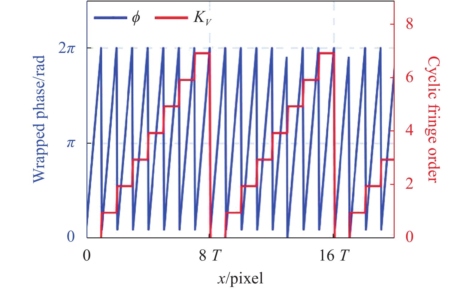
In general, three GC patterns can encode 8 fringe periods. When the number of fringe periods is greater than 8, the fringe order
${K_V}$ obtained from the three GC patterns will be cyclic, as shown in Fig. 5. Thus, the unwrapped phase recovered by cyclic fringe order${K_V}$ is not continuous and ranges from 0 to$16\pi $ with$16\pi $ discontinuities, which is called as pseudo unwrapped phase${\varPhi _P}$ in this paper. To remove the$16\pi $ discontinuities,${\varPhi _P}$ can be further unwrapped using the geometric constraint method.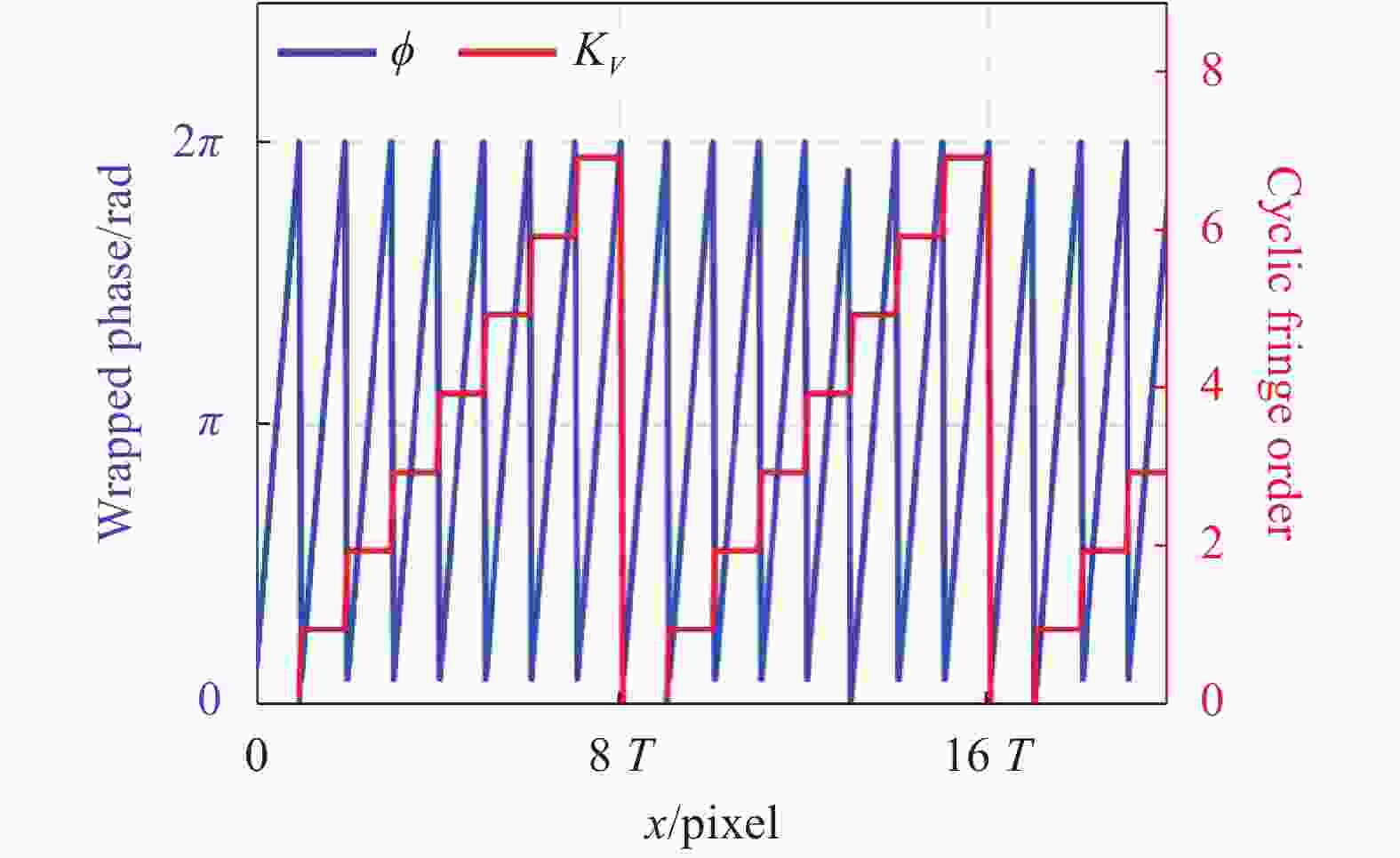
Figure 5. Cross sections of wrapped phase
$\phi (x,y)$ , cyclic fringe order${K_V}$ As mentioned above, the pseudo unwrapped phase
${\varPhi _P}$ with several periods can be unwrapped using${\varPhi _{\min }}$ based on the geometric constraint method. Figure 6 shows a case wherein${\varPhi _{\min }}$ is used to unwrap${\varPhi _P}$ , which contains several$16\pi $ discontinuities: E, F, and G. Similarly, we can calculate the cycle order${K_P}$ of${\varPhi _P}$ as:
Figure 6. Fundamental idea of employing
${\varPhi _{\min }}$ for unwrapping${\varPhi _P}$ Finally, the absolute phase
$\varPhi $ can be finally determined as Eq.(12). Compared with the conventional geometric constraint method[27], the proposed method can theoretically extend the measurement range from$2\pi $ to$16\pi $ . -
To evaluate the enhanced GC approach, a DFP system, containing a projector (DLP Light-Crafter 4500) and camera (Point Gray Chameleon 3), was implemented. The camera resolution is 1280×1024 pixel, and it was synchronized using the projector's trigger signal. The optical lens has a focal length of 8 mm. The projector has a resolution of 912×1140 pixel. The measured objects were placed at a distance of approximately 60 cm in front of the DFP system, and a smooth board was used as the reference plane. In the following experiments, the fringe period in the enhanced GC method was set to 21 pixel.
In the first experiment, we compared the proposed method to the conventional geometric constraint method. A large sphere with a smooth surface was measured based on the two approaches. The absolute phase maps were derived for reconstructing the 3D shape of the sphere. The results of the 3D reconstruction using the two methods were then compared. Figure 7 presents the sphere's captured images. The wrapped phase
$\phi $ was obtained using the three-step phase-shifting algorithm, and the cyclic fringe order${K_V}$ with several cycles was calculated from the three GC patterns. The pseudo unwrapped phase${\varPhi _P}$ was obtained using Eq.(7), and${\varPhi _P}$ was further unwrapped to an absolute phase using the geometric constraint method. Figures 8(a) and (b) show the 3D reconstructions made using the conventional geometric constraint approach and the presented approach, receptively. The phase difference of the two methods in Fig.8(c) indicated that conventional geometric constraint method fails, while the proposed method can work well. The experimental results demonstrate that the proposed approach has a broader measurement range compared with the conventional geometric constraint one.
Figure 7. Images of the sphere. (a) Sinusoidal fringe pattern; (b) GC pattern; (c) Wrapped phase map; (d) Fringe order map; (e) Pseudo unwrapped phase map; (f) Minimum phase map; (g) Unwrapped phase map; (h) Absolute phase map
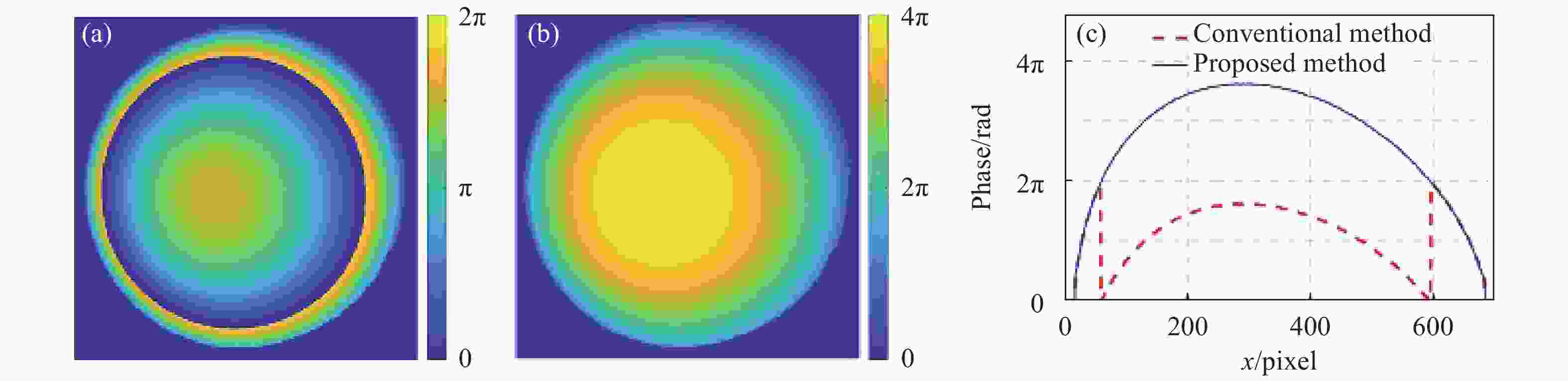
Figure 8. Reconstructed 3D shapes of a sphere. (a) Conventional geometric constraint method; (b) Proposed method; (c) Cross-sections of (a) and (b)
In the second experiment, we compared the proposed method with the conventional GC method using three groups of patterns. In the first group of patterns, we used the same number (three) of GC patterns as the proposed method, three GC patterns can encode 8 fringe periods. Thus, the first group of patterns used three sinusoidal fringe patterns with T=114 pixels and three GC patterns. In the second group of patterns, we used the same sinusoidal fringe period (T=21 pixels) as the proposed method. Thus, the number of corresponding fringe periods was
$Ceil\left[ {912/21} \right]{\rm{ = }}44$ . And the number of required GC patterns was$Ceil\left[ {{{\log }_2}44} \right]\!=\!6$ . Thus, the second group of patterns used three sinusoidal fringe patterns with T=21 pixels and six GC patterns, and the last used three sinusoidal fringe patterns with T=21 pixels and three GC patterns with several cycles. Figure 9 presents the reconstructed 3D shapes, respectively, reconstructed using the conventional GC method with three GC patterns, six GC patterns, and enhanced GC method. Figure 9(a) shows the 3D shape reconstructed by conventional GC method using three sinusoidal fringe patterns with T=114 pixels and three GC patterns. Figures 9(b) shows the 3D shape reconstructed by conventional GC method using three sinusoidal fringe patterns with T=21 pixels and six GC patterns. Figure 9(c) shows the 3D shape reconstructed by the proposed approach using three sinusoidal fringe patterns with T=21 pixels and three GC patterns. Figure 9(d)-(f) show the cross-sections of the three reconstructed results. The cross-section of the presented approach is much smoother than that of traditional one with three GC patterns, thus proving that the proposed method can achieve a more accurate 3D reconstructed results than conventional method when using the same number of GC patterns. And the cross-sections of the proposed method and the conventional GC method with six GC patterns are the same in each pixel, thus it proves that the proposed method can enhance the measurement efficiency while using the same fringe period.
Figure 9. Reconstructed 3D shapes of the Doraemon sculpture. (a) Conventional GC method using three sinusoidal fringe patterns with T=114 pixels and three GC patterns; (b) Conventional GC method using three sinusoidal fringe patterns with T=21 pixels and six GC patterns; (c) Proposed method using three sinusoidal fringe patterns with T=21 pixels and three GC patterns; (d)-(f) Cross-sections of (a)-(c)
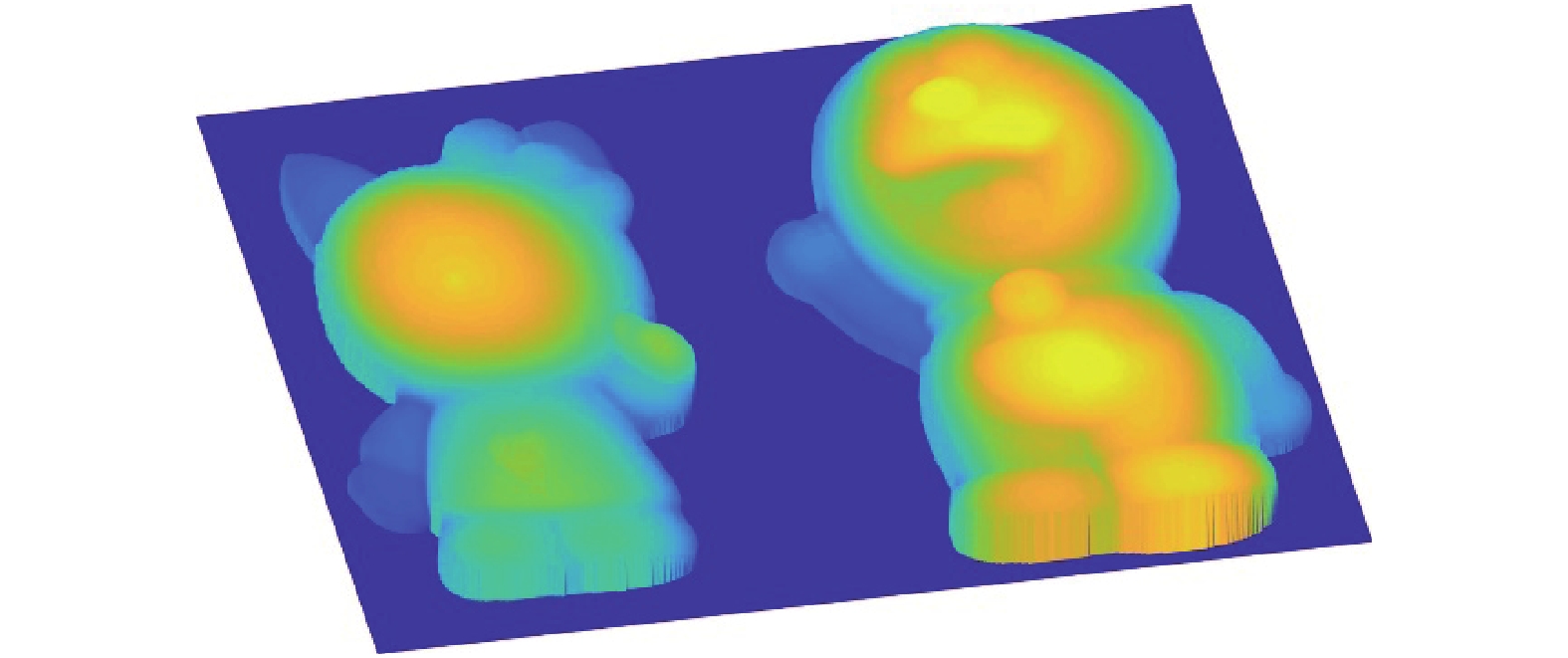
Finally, we applied our method to measure two isolated sculptures. Figure 10 presents the 3D reconstructed shape of the two sculptures. The experiments demonstrate that the presented approach can reliably measure multiple isolated objects.
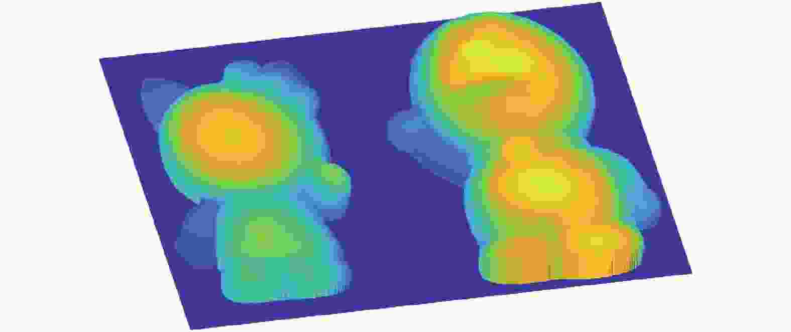
Figure 10. Reconstructed 3D shape of two isolated sculptures
-
This paper presents an enhanced GC approach for 3D shape measurement based on geometric constraint method. Based on the cyclic coding strategy, we used N GC patterns with M cycles to unwrap the wrapped phase with
$M\times{2^N}$ periods, whereas only${2^N}$ fringe periods can be determined when using N conventional GC patterns. N denotes the number of GC patterns. We can choose a suitable N in different measuring cases. Compared with the conventional geometric constraint method, the enhanced GC method extends the measurement range from$0$ to${2^{(N + 1)}}\pi $ in the phase domain. Furthermore, all the projected 8-bit patterns are converted into 1-bit ones using the binary dithering technique to increase the acquisition speed. Thus, the proposed enhanced GC method has potential for high-speed 3D shape measurements.
Enhanced Gray-code method for three-dimensional shape measurement
doi: 10.3788/IRLA20200314
- Received Date: 2020-08-26
- Rev Recd Date: 2020-09-29
- Publish Date: 2020-11-25
-
Key words:
- phase unwrapping /
- 3D measurement /
- fringe projection /
- Gray-code /
- geometric constraint
Abstract: Conventional Gray-code (GC) plus phase-shifting methods have been extensively utilized for three-dimensional (3D) shape measurements. Nevertheless, how to achieve fast and accurate measurement remains challenging because multiple GC patterns are necessary for absolute phase recovery. An enhanced GC method based on geometric constraint was proposed, which would decrease the number of fringe patterns. The 8-bit phase-shifting patterns could be transferred into 1-bit binary ones by using the binary dithering approach to realize high-speed projection. Specifically, a total of six binary patterns including three phase-shifting patterns and three GC patterns were employed in the proposed method. The phase-shifting patterns were adopted to compute the wrapped phase, and then the GC patterns could be utilized to unwrap the wrapped phase to obtain a pseudo unwrapped phase. In the end, the absolute phase would be reconstructed after using the geometric constraint to unwrap the pseudo unwrapped one. The experiments demonstrate that the enhanced GC method is an effective way to reconstruct the 3D shapes of measured objects.


 DownLoad: