


-
超低频振动校准技术在航空航天、精密制造、地震和海啸预警等领域具有重要意义[1-2]。超低频超大振幅标准振动台是进行超低频振动校准的关键装置。对振动台在超低频段的性能测试是一个难点,为了获得高精度的测试结果,多采用先进的多通道零差激光干涉方法对振动台不同频率的振动进行测量。对0.01 Hz的超低频振动而言,电磁振动台产生峰峰值为1 m的标准正弦位移波形时,最大运动速度可达几十毫米每秒,而其单周期运行时间长达100 s,且经常需要多周期测量。故被测标准振动信号高速、高精度、长时间的测量要求,对现有测量方法[3-4]提出了挑战。
具体而言,零差激光干涉测量方法在超低频振动校准中的应用主要受两方面限制[5-9]。
首先,零差激光干涉的两路正交信号通常存在直流偏置、不等交流幅值和非正交相移误差,简称“三差”,给测量结果带来非线性误差。其中直流偏置、不等交流幅值误差可利用硬件电路或软件算法简易修正,而非正交相移误差的补偿比较困难,目前主要有两种方法,(1)通过软件算法补偿,采用海德曼修正时对参数的计算涉及由采样数据组成的矩阵变换,特别是矩阵求逆等操作,但过大的数据量组成的矩阵维度很大,将直接导致计算费时且困难等问题[7-10];(2)利用J. Ahn等人提出的基于波片轴线调整的硬件补偿方法[11],理论上可实现实时非正交相移误差计算,但由于偏振分光器偏振混叠和消偏振分光器相位漂移误差的存在,波片角度偏差的非正交相移误差灵敏度可高达3°/1°,即波片的安装角度偏差(装配误差、机械漂移等)会引入较大的非正交相移误差。
其次,根据奈奎斯特定理,数据采样率须大于干涉条纹最大变化频率的2倍。使用波长为632.8 nm的激光光源搭建多通道零差正交激光干涉光路,测量频率为0.01 Hz、幅值为0.5 m的振动时,如采用传统的连续条纹相位解调算法[12],需要高达200 kHz的采样频率,多振动周期的测量时间长达数百秒。故高采样率、长测量时间以及随之产生的大量数据对激光干涉的硬件性能提出了更高要求。
文中针对零差激光干涉在超低频振动台性能评价中非正交相移误差补偿困难,测量时采样率要求高,数据量庞大的问题,基于波片偏航相移误差补偿方法和卡尔曼正交信号解调算法,提出一种欠采样激光干涉测量方法,并通过仿真和实验进行性能验证。
-
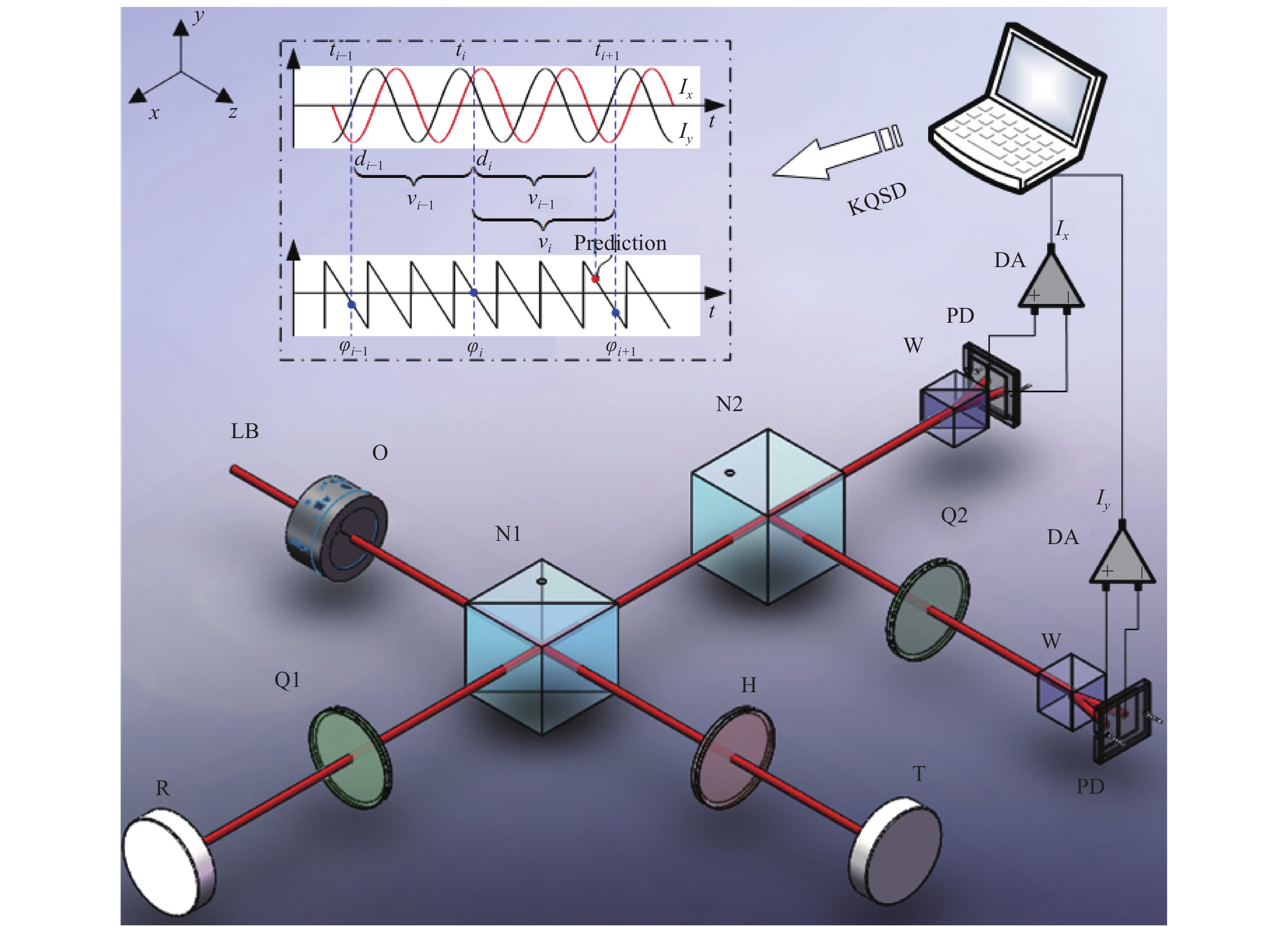
如图1所示,在前期对零差正交干涉关键技术研究基础上[13],基于波片偏航非正交相移误差补偿方法和卡尔曼正交信号解调算法,提出一种欠采样零差正交激光干涉方法。为最大限度地减少偏振混叠及分光不平衡性,降低“三差”,基于消偏振分光原理进行光路设计。

Figure 1. Schematic diagram of undersampling homodyne quadrature interferometry measurement method. LB, Laser beam;O, Optical Faraday isolator;N1, Non-polarizing beam splitters 1;N2, Non-polarizing beam splitters 2;Q1, Quarter-wave plate 1;Q2, Quarter-wave plate 2;W, Wollaster prism;H, Half-wave plate;R, Reference mirror;T, Target mirror;PD, Photodetector;DA, Differential amplifier;KQSD, Kalman quadrature signal demodulation
图1中,He-Ne激光器产生波长为632.8 nm的稳频线偏振激光束(LB)。采用光学法拉第隔离器O防止光束返回;消偏振分光器1(N1)的入射光束被平均分成测量光和参考光,它们的偏振方向正交,且在测量光两次通过半波片H,参考光两次通过1/4波片1(Q1)后,在N1处合光;通过固定参考镜R移动目标镜T,引入测量光的相位变化被由两个光电探测器PD组成的正交解调器测量,其中一个接收由测量光和参考光之间的1/4波片2(Q2)引起的90°相位差;从O输出的光偏振平面相对于平面xoz的夹角为45°,因此H、Q1和Q2的光轴相对于y轴的角度
${\psi _i}$ (i=1、2、3)分别为0°、0°和45°,渥拉斯特棱镜W位于平面xoz上。差分放大器DA输出的正交信号为
${I_x}$ 和${I_y}$ ,经A/D转换器数字化后在计算机中进行处理。根据正交信号序列计算出第i个采样时刻的测量位移${d_i}$ :式中:
$\lambda $ 为激光在空气中的波长;${k_i}$ 为条纹计数的整数部分。针对波片光轴与其理想装配角偏差引起非正交相移误差的问题,在基于消偏振分光的零差正交激光干涉测量光路中,采用波片偏航的方法补偿相移误差,并实现偏差的非正交相移误差灵敏度最小化,完成硬件实时补偿。
设非正交相移误差为
$\alpha $ ,理想情况下当波片安装角度${\psi _1}$ =0°、${\psi _{\rm{2}}}$ =0°、${\psi _{\rm{3}}}$ =45°时,$\alpha $ =0且${\rm d}\alpha /{\rm d}{\psi _i}$ =0 (i=1,2,3)。由于非偏振分光镜的涂层和粘合剂的透射和反射,不可避免地会引入额外的相移误差和水平与垂直分量之间的分光比误差[14-15],从而增大相移误差及其对波片角度偏差的灵敏度,即$\alpha $ >0且$({\rm d}\alpha /{\rm d}{\psi _i})$ >0 (i =1,2,3)。在此实际工况下,由装配误差或机械漂移引起的波片光轴与其理想装配角的轻微偏差将引入显著的相移误差。如图2(a)所示,当光束垂直入射到波片上时,由于消偏振分光镜不同入射面的透射和反射,将会在测量光、参考光电场矢量
${E_{\rm m}}$ 、${E_{\rm r}}$ 上产生附加相移${M_1}$ 、${R_1}$ 、${M_2}$ 和${R_2}$ 。如图2(b)所示,为了消除附加相移对非正交相移误差灵敏度的影响,在测量臂和参考臂上对波片进行微小偏航。根据折射定律,随着偏航角的增大,波片的相位延迟也随之增大。故存在一组偏航角度,使半波片和1/4波片1的相位延迟增量满足${M'_1} - $ $ {R'_1} = 0$ ,${M'_2} = 0$ ,${R'_2} = 0$ 。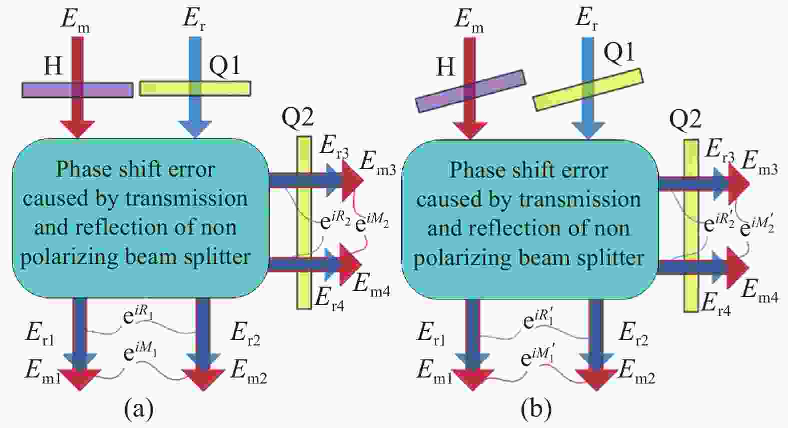
Figure 2. (a) Normal beam incident to wave plates; (b) Non quadrature phase error compensation by yawing wave plates
补偿后波片的非正交相移误差与波片安装角度的关系可表示为:
非正交相移误差对波片角度偏差的灵敏度为:
同时考虑水平分量和垂直分量的相移误差和分光比误差,应用Jones算法,从理论上分析非正交相移误差及其对波片角度偏差的灵敏度,以验证文中所提出方法的正确性。分析过程中,消偏振分光镜(Thorlabs,BS013,50%:50%)的透射和反射Jones矩阵需要实验确定。
如图3和图4所示,在应用波片偏航非正交相移误差补偿方法前,当
${\psi _1}$ =0°、${\psi _2}$ =0°、${\psi _3}$ =45°时,Q1的非正交相移误差为2°,灵敏度为1.4°/1°,虽然旋转它可以抑制其相移误差,但灵敏度保持不变。相移误差主要来源于消偏振分光镜,采用文中方法后被抑制到零,其对波片角度偏差的灵敏度也显著降低,理论上当波片按理想角度装配时为零。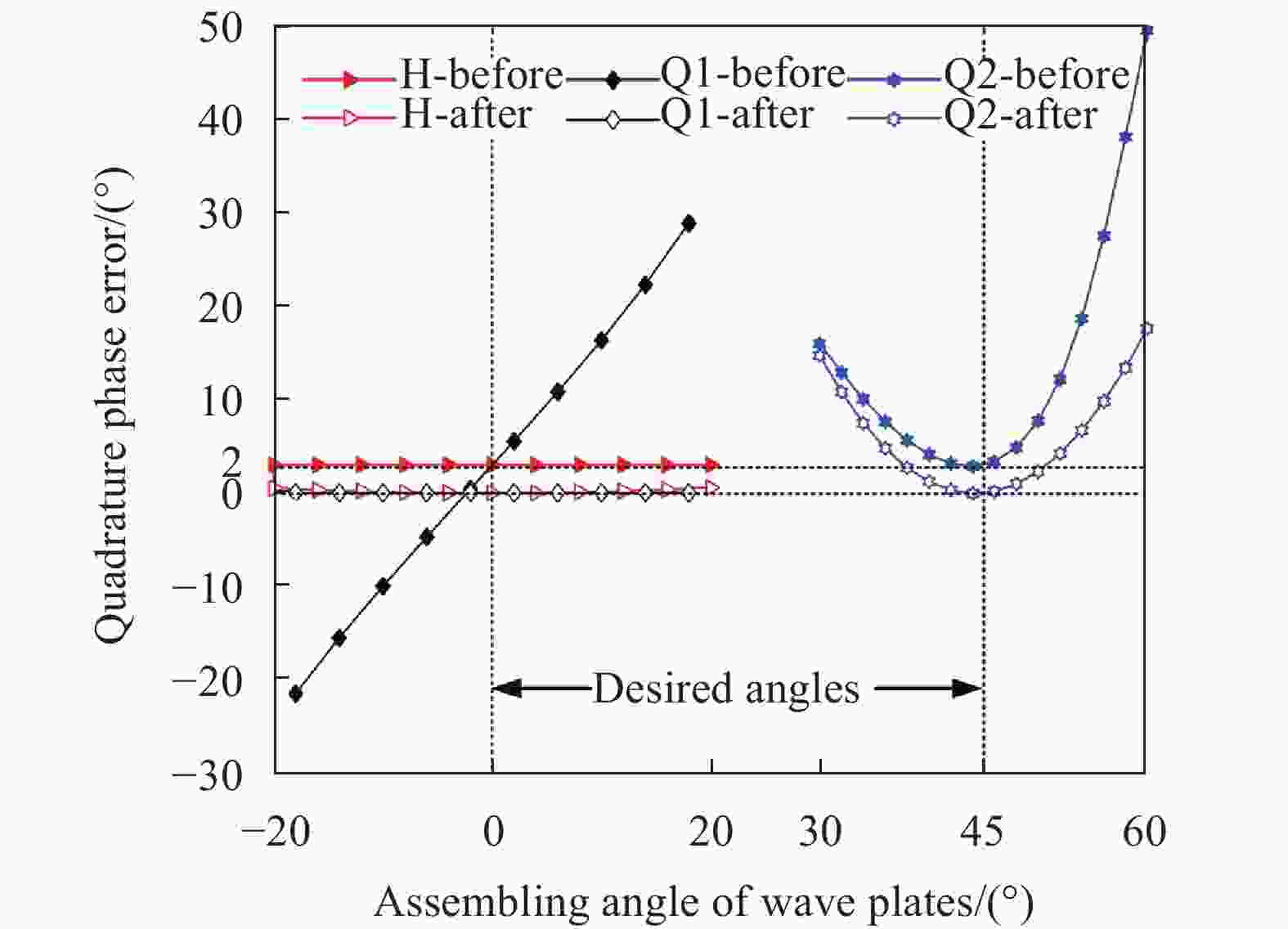
Figure 3. Simulation results of non quadrature phase error introduced by angle deviations of wave plates

Figure 4. Simulation results of non quadrature phase error sensitivities to angle deviations of wave plates
针对测量数据量庞大,难以快速处理的问题,提出一种基于运动状态预估的卡尔曼正交信号解调算法[16-19],可对深度欠采样数据的条纹相位信号进行解调,以实现降低所需采样率和采样数据量的效果,从而满足超低频超大振幅标准振动测试所提出的高速、长时、高精度的需求。
卡尔曼正交信号解调算法的基本思路是先估计当前的位移,即当前估计的相位整数和小数,然后通过比较估计和实际相位小数来确认实际的相位整数,最后实现欠采样数据的相位解调。该算法可表示为:
式中:
${\varphi}$ ,$\tilde v$ ,$\tilde d$ ,$\tilde k$ ,$\tilde \varphi $ 分别为相位序列、速度、位移、相位整数和相位分数部分的预估结果;$\Delta T$ 为采样时间间隔;$round\left( x \right)$ 为取整;$rem\left( {x,y} \right)$ 为取余,即$rem\left( {x,y} \right) = $ $ x - ny$ ,其中$n = round\left( {x/y} \right)$ 。假设位移是时间的连续函数,且在时间上可微,则其二阶泰勒展开式为:
式中:
${v_{}}$ 和$a$ 分别为速度和加速度。与公式(6)相比,位移预估值的最大误差${d_{\rm error}}$ 为:为避免位移预估值的不连续,
${d_{\rm error}}$ 应小于$\lambda /4 - $ $ 2erro{r_{\operatorname{PV} }}$ ,其中$erro{r_{\operatorname{PV} }}$ 为残余非线性误差的峰峰值。因此,采样率fs应满足:卡尔曼正交信号解调算法所需的最小采样率取决于峰值加速度
${a_{\rm peak}}$ ,而不是现有采用连续条纹相位解调算法的峰值速度[12]。因此,该方法可实现信号的深度欠采样和数据量的大幅减少,可解决超低频振动台性能评价过程中所需采样率高、数据量大的问题。 -
搭建如图5所示的欠采样零差正交干涉测量实验装置。波片安装在可旋转支架上以方便调整光轴;正交信号由数据采集卡进行等间隔采样。实验装置搭设在自动调平光学隔振平台上,实验在洁净室中进行,以减少环境影响。

Figure 5. Experimental setup of undersampling homodyne quadrature interferometry measurement method
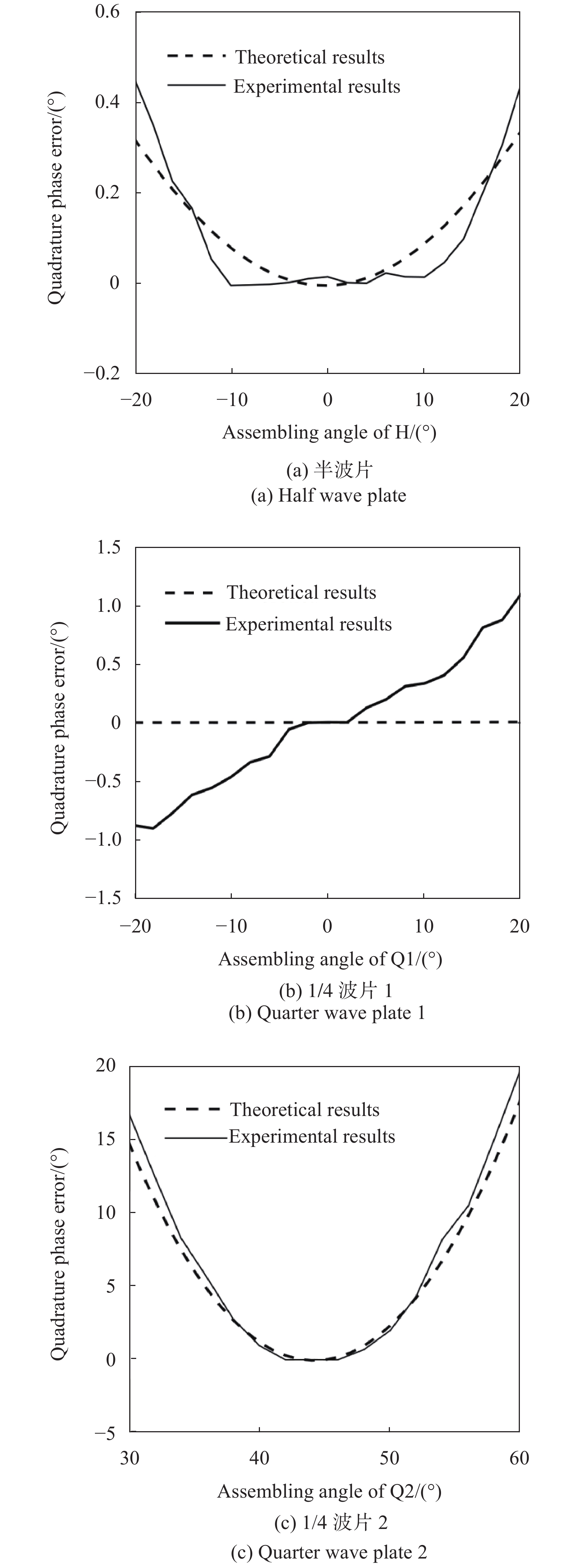
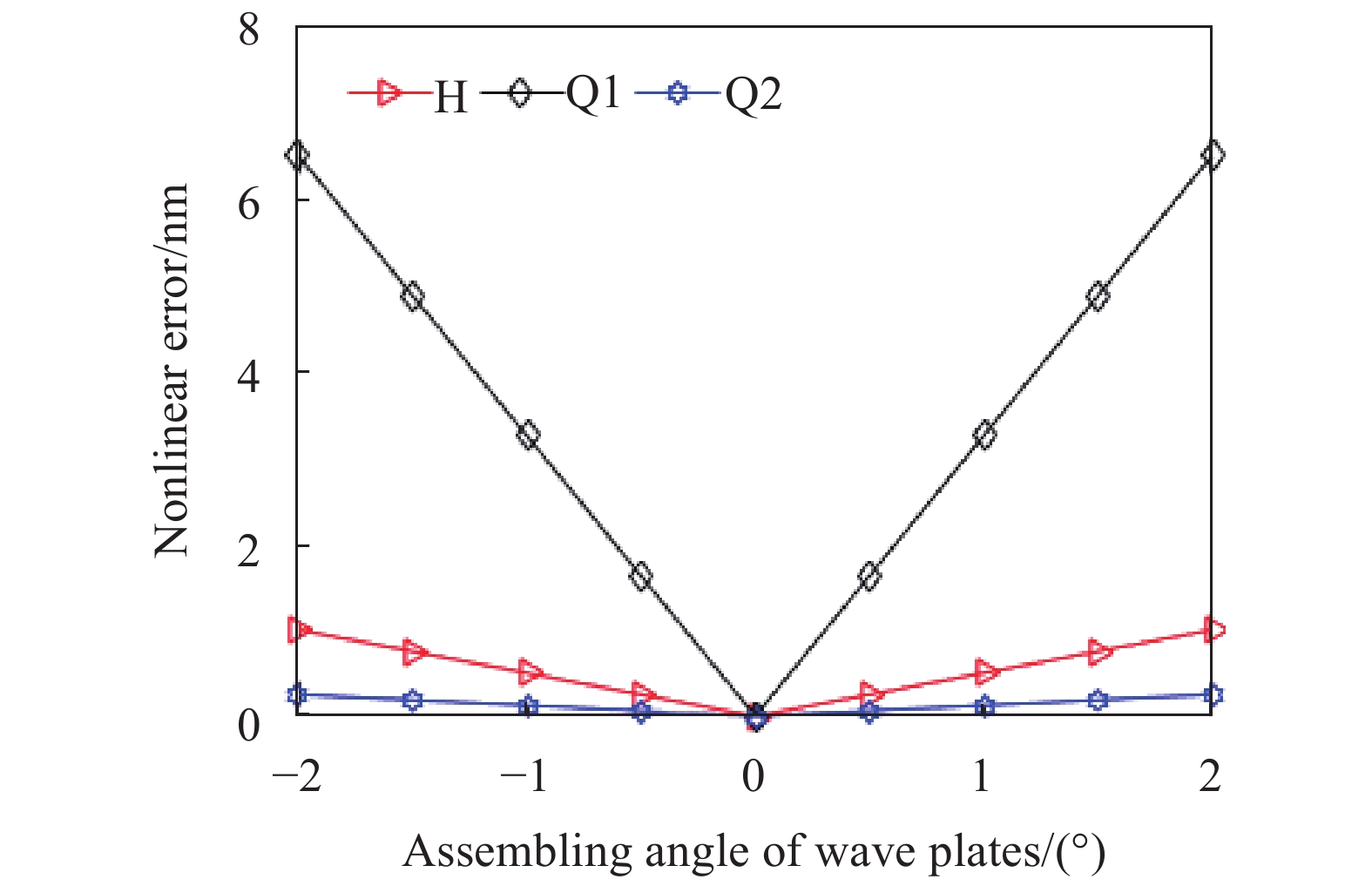
首先,进行欠采样零差正交干涉的硬件非正交相移误差补偿实验,实验结果如图6和图7所示,虽然波片偏航角度存在一定的安装误差,结果无法与理论完全相同,但也能够将非正交相移误差基本调整为0,半波片、1/4波片1、1/4波片2的非正交相移误差对角度偏差的灵敏度分别降低至0、0.05°/1°和0,非线性误差减小至近似为0。

Figure 6. Experimental results of quadrature phase error vs. optical axis angles of wave plate

Figure 7. Experimental results of nonlinear error varying with the assembling angle of wave plate
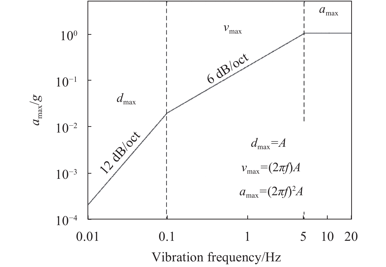
由稳态正弦振动发生标准装置的实际特性可知其振动频率与最大加速度的关系曲线如图8所示。根据该曲线模拟振动台波形测量实验,验证卡尔曼正交信号解调算法的欠采样性能,同时假设欠采样零差正交干涉测量产生的非正交相移误差为0.07°。连续条纹相位解调算法和卡尔曼正交信号解调算法的最小采样率要求以及10个振动周期存储容量需求如图9和图10所示,0.01 Hz振动频率下因非正交相移误差产生的剩余误差如图11所示。

Figure 8. Relation curve between amax and vibration frequency

Figure 9. Sampling rate vs. vibration frequency
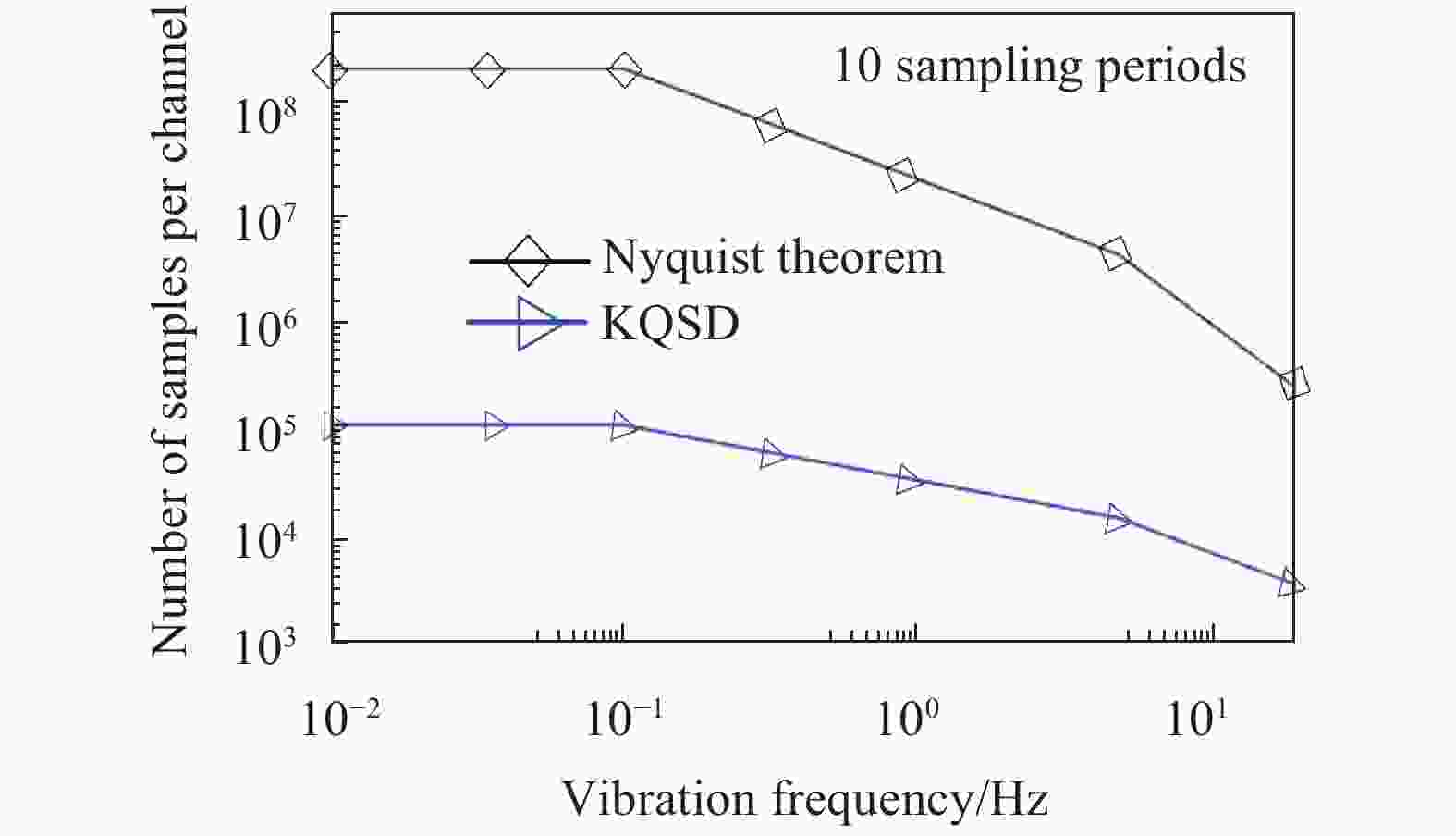
Figure 10. The sampling numbers of interference fringe as a function of vibration frequency in low frequency vibration
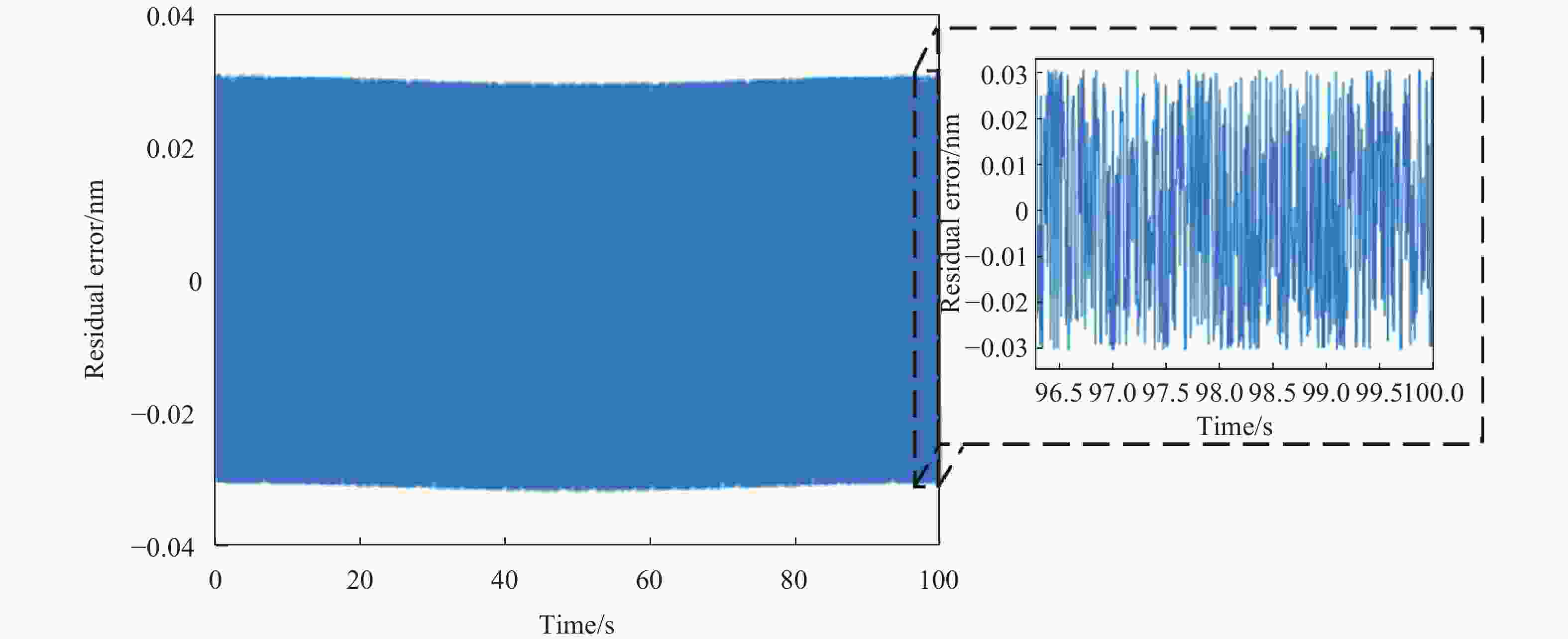
Figure 11. Residual error between demodulation vibration signal and the standard sinusoidal vibration for 0.01 Hz
由图9和图10可知,在(0.01~0.1) Hz频段,根据奈奎斯特采样定理,采样率需高达200 kHz (
${f_{\rm s}} = $ $ {{4{v_{\max }}} / \lambda }$ ,其中vmax为被测物运动的最大速度[12, 20]),且在不断增大,数据采集点数高达200 M/通道(每10个振动周期),对数据采集处理系统提出了更高要求;卡尔曼正交信号解调算法所需的采样率为112 Hz,每通道数据采集点数最大只有0.112 M/通道(每10个振动周期),均降低至奈奎斯特采样定理的0.056%。由图11可知,由非正交相移误差引起的剩余误差峰峰值约为0.063 nm,因此,所提出的欠采样零差正交干涉测振方法在保持激光干涉纳米测量精度的前提下,实现了深度欠采样,大幅降低了采样率和采样数据量,可满足超低频标准振动台高精度性能测试的需求。 -
文中提出了一种欠采样零差正交激光干涉测振方法,解决了在超低频超大振幅标准振动台性能评价中应用激光干涉方法的困难。搭建了基于消偏振分光原理和波片偏航法的硬件光路,将正交激光干涉测量方法的非正交相移误差以及其对波片角度偏差的灵敏度减小至0;在测量(0.01~0.1) Hz频段振动时,卡尔曼正交信号解调算法的采样率和每通道数据采集点数均降低至奈奎斯特采样定理的0.056%。因此,文中提出的欠采样零差正交干涉测振系统可有效评价超低频超大振幅标准振动台的性能,且同样普适于其他超低频振动校准系统,是一种高速、高精度、长时间校准超低频振动的较理想解决方法。
Homodyne quadrature laser interferometry measurement method for large amplitude, long cycle vibration calibration
doi: 10.3788/IRLA20200329
- Received Date: 2020-11-20
- Rev Recd Date: 2021-01-14
- Publish Date: 2021-06-30
-
Key words:
- homodyne quadrature laser interferometry measurement method /
- quadrature phase error /
- undersampling /
- Kalman quadrature signal demodulation /
- vibration calibration
Abstract: In order to carry out performance testing of ultra-low frequency standard vibration table with large amplitude, an undersampling homodyne quadrature laser interferometry measurement method was proposed in this paper. Based on the design of depolarization beam splitting measurement optical path, a wave plate yaw adjustment method was proposed to compensate hardware of the quadrature phase error in real time. The Kalman quadrature signal demodulation algorithm based on motion state estimation was presented to demodulate the interference fringes of deep undersampling to reduce the sampling rate and the amount of data produced. The experimental and simulation results show that the quadrature phase error and its sensitivity to the angle deviations of wave plates are significantly reduced, the sampling rate of the Kalman quadrature signal demodulation algorithm and number of samples per channel are reduced to 0.056% of Nyquist sampling theorem for measuring ultra-low frequency vibration. The undersampling homodyne quadrature laser interferometry measurement method proposed in this paper can meet the requirements of ultra low frequency and ultra large amplitude standard vibration measurement.


 DownLoad: