


-
随着空间技术的不断发展,各类光学载荷分辨率及数据量急剧增加,对大容量星地信息传输技术的需求也愈加强烈。激光通信具有大通信容量、高传输速率、高隐蔽性、高抗干扰能力等优点,是星地大容量信息保密通信最具竞争力的可选方案,是满足民用、军用高码速率大容量通信方式的重要手段[1-3]。
激光通信光学天线像质要求非常高[4-5],系统波像差RMS普遍都在λ/10~λ/30之间。光学天线多采用卡式系统,主镜面形RMS常需要达到λ/60左右。目前,激光通信技术中多数选用近红外波段(1550 nm和800 nm波段)进行信息传输,光学天线加工装调要求精度高,难度大,价格昂贵。此外,受大气衰减、大气闪烁等大气效应的影响,在天气条件较差时,近红外波段星地激光试验系统的可通率难以满足星地激光高速数传工程的应用需求。而且,浓雾及雾霾等恶劣天气频频出现的气候,使得近红外波段星地激光试验系统更加难以保障星地通信性能的稳定传输。中红外3~5 μm是重要的大气窗口[6],选用中红外波段进行信息传输,其波长是近红外波段的2倍以上。波长越长,抗大气干扰能力越强,光学天线越容易达到衍射极限,加工装调精度要求就会降低,从而可以降低成本。
文中依据激光通信能量链路传输方程计算了中红外激光通信光学天线设计参数,设计加工了一套中波红外激光通信终端光学系统,完成了系统研制。
-
激光通信的能量链路传输方程可以用以下的通用表达式描述[7]:
式中:
${P_{\rm{r}}}$ 为探测器接收功率;${P_{\rm{t}}}$ 为发射光源的发射功率;${G_{\rm{t}}}$ 为发射光学天线增益;${\eta _{{\rm{ot}}}}$ 为发射光学单元的效率;${L_{\rm{r}}}$ 为自由空间损耗;${\eta _{\rm{s}}}$ 为信道引起的功率损失;${L_{{\rm{APT}}}}$ 为APT对准失配引起的功率损耗;${G_{\rm{r}}}$ 为接收光学天线增益;${\eta _{{\rm{or}}}}$ 为接收光学系统效率;${\eta _{\rm{\alpha }}}$ 为实际束散角与衍射极限角的额外功率损耗。激光通信光源为量子级联中红外激光器[6],可调制功率60 mW,在BER=10−6、1 Gbps时探测器极限灵敏度为−12 dBm;通信距离10 km。接收功率计算表如表1所示。由表1可知,当激光通信有效接收口径为310 mm,通信发射角0.3 mrad,发射光学天线波像差RMS≤λ/10 (λ为通信波长),通信距离可达10 km,留有2.52 dB的裕量。
Parameter Specification Notes Communication transmitting power/dBm 17.78 Laser modulation power is 60 mW,Laser wavelength is 4.7 μm Transmitting antenna gain/dB 85.51 The emission aperture is 290 mm Transmitting antenna loss/dB −2.22 Transmitting optical efficiency is 0.6 Wavefront loss/dB −1.71 Wavefront aberration RMS≤0.1λ,λ= 4.7 μm Space loss/dB −208.5 10 km Alignment adaptation loss/dB −0.01 High alignment precision Atmospheric absorption/dB −3.62 Atmospheric attenuation Receiving antenna gain/dB 106.1 The receiving aperture is 310 mm Receiving antenna loss/dB −2.22 Receiving optical efficiency is 0.6 Detector actual receiving power/ dBm −9.48 Actual arrival power to detector Detector receiving threshold/dBm −12 BER=10−6,1 Gpbs Table 1. Calculation table of midde infrared laser communication link
-
文中采用的激光器为量子级联中波红外激光器,其出射波长
$\lambda = 4.7\;{\rm{{\text{μ}} m}}$ ,光束直径${D_1} = 7\;{\rm{mm}}$ ,发散全角${\theta _1} = 10\;{\rm{mrad}}$ 。选取发射光学天线出瞳口径${D_2} = $ $ 290\;{\rm{mm}}$ ,通信光束经发射光学天线出射后的束散全角${\theta _2}$ 可由下式计算:可得
${\theta _2} =$ 241.4 μrad$ \leqslant $ 300 μrad,满足能量链路计算要求。利用光束远场衍射传输模型,可建立高斯光束远场分布与发射光学系统波像差之间的关系如下所示[7]:当波像差RMS值为0.1波长时,波像差引起的发散角增大量约为51 μrad,此时发散角为292.4300 μrad,仍满足小于300 μrad的要求。
发射光学天线将量子级联中波红外激光器出射的激光光束进行准直扩束。扩束光学系统有伽利略式和开普勒式两种结构,伽利略式扩束结构无中间实焦点,对于扩束倍率较大的系统,需采用两级扩束,且从物镜组次镜发出的光线发散角较大,使得主镜口径随着主次镜间距显著增加,明显大于扩束计算所得理论值。文中发射光学天线采用开普勒式望远镜倒置结构,由物镜组和目镜组两部分构成,如图1所示。

Figure 1. Diagram of inverted structure of Kepler telescope
物镜组和目镜组焦距之比等于出瞳和入瞳直径之比:
为便于物镜组、目镜组单独装调、检测,提高研制效率,分别对物镜组、目镜组单独设计,对两者进行组合后单独优化目镜组场景以保证瞳孔匹配。
为减小发射光学天线总长,物镜组采用两镜经典卡塞格林结构,且焦面设置在主次镜之间。设主镜和次镜的二次非球面变形系数分别为
$e_{_1}^2$ 、$e_2^2$ ,主镜为抛物面$e_{_1}^2 = 1$ ,次镜为双曲面$e_2^2 > 1$ 。为便于主镜加工,其F#不宜小于1,在总长允许的前提下尽量提高主镜焦距。选择主镜焦距初值${f_{\rm{p}}} =\; 400\;{\rm{mm}}$ ,主镜F#为1.38。物镜总焦距为:式中:
$\;\beta $ 为次镜的放大倍率,将主镜焦距放大,且次镜为凸面,因此$\;\beta < - 1$ 。在设计中,保持主镜焦距及$e_{_1}^2 = 1$ 不变,以次镜半径、主次镜间距、像面位置为变量,保持$e_2^2 > 1$ ,通过改变次镜焦距,权衡确定焦面位置和中心遮拦比,最终定为$\;\beta = - 8.5$ ,此时${f_{\rm{o}}} = 3\;400\;{\rm{mm}}$ ,中心遮拦比0.103,物镜如图2所示。
Figure 2. Optical path diagram of transmitting optical antenna objective lens
将物镜组焦距代入公式(4)可得目镜组焦距
${f_{\rm{e}}} = $ $ 82.07\;{\rm{mm}}$ ,全视场等于量子级联激光器发散全角,$2\omega = $ $ {\theta _1} = 10\;{\rm{mrad}}$ ,入瞳直径${D_{\rm{e}}} = 7\;{\rm{mm}}$ ,波长$\lambda = 4.7\;{\text{μm}}$ 。设计要求温度适用范围5~35 ℃,物镜组为反射结构,主次镜材料均采用铝(7075),结构件均采用铝(6061),两者热涨系数非常接近,温度变化对像质影响不大。而目镜组采用透射结构,红外透镜光焦度、镜筒长度都随温度变化而改变,因此,目镜组需进行无热化设计。薄透镜的归一化光焦度温度系数$T$ 为[8]:式中:
${\alpha _0}$ 为透镜的热膨胀系数。薄透镜组归一化光焦度温度系数${T_{\rm s}}$ 为:式中:
$m$ 为透镜数量;$\varphi $ 为总光焦度;${\varphi _i}$ 为各透镜光焦度。目镜组的消热差设计即考虑镜筒随温度变化导致的像面变化$\Delta {L_1}$ 与透镜随温度变化导致的焦面变化$\Delta {L_2}$ 在使用温度范围内尽可能相互补偿,即:式中:
${\alpha _{\rm{H}}}$ 为镜筒的热膨胀系数。折射光学元件一般具有正热差性,即$ T>0$ ,而镜筒亦具有正热差性,要使用公式(8)进行补偿,镜组中负透镜的热膨胀系数需尽可能大。由于目镜组F#较大,像差校正较为容易,采用“正-负-正”三透镜结构形式进行光焦度分配,透镜材料为“ZnS-CAF2-ZnS”。在对目镜组单独优化完成后,将物镜组和目镜组进行组合,选择无焦模式做进一步优化。组合优化时保持物镜组不变,入瞳设置在主镜上,以目镜组透镜半径和间距作为变量,以出瞳直径和出瞳位置作为优化目标,用波像差进行评价,实现物镜组和目镜组衔接时的瞳孔匹配,设计完成的发射光学天线如图3所示。
Figure 3. Optical path diagram of transmitting optical antenna
发射光学天线为无焦系统,其MTF曲线如图4(a)所示,各视场传递函数都达到了衍射极限;系统波前如图4(b)所示,波像差PV值为0.0055λ,RMS值为0.0014λ,λ=4.7 μm。

Figure 4. Design results of transmitting optical antenna. (a) MTF; (b) Diagram of wavefront aberration
-
接收光学天线负责对通信光束的会聚接收,其口径决定了接收天线增益,口径越大,可接收能量越多,增益越大。接收光学天线也采用经典卡塞格林两反结构,其设计过程与发射光学天线物镜组基本一致。接收光学天线光路如图5所示,口径310 mm,主镜为抛物面,通光口径310 mm;次镜为双曲面,通光口径78.34 mm;最后有一片滤光片,厚度2 mm,材料为ZnS;焦距1550 mm,接收全视场0.03°,满足聚焦光斑效率探测器直径1 mm的要求。
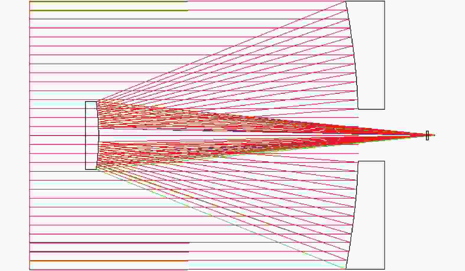
Figure 5. Optical path diagram of receiving optical antenna
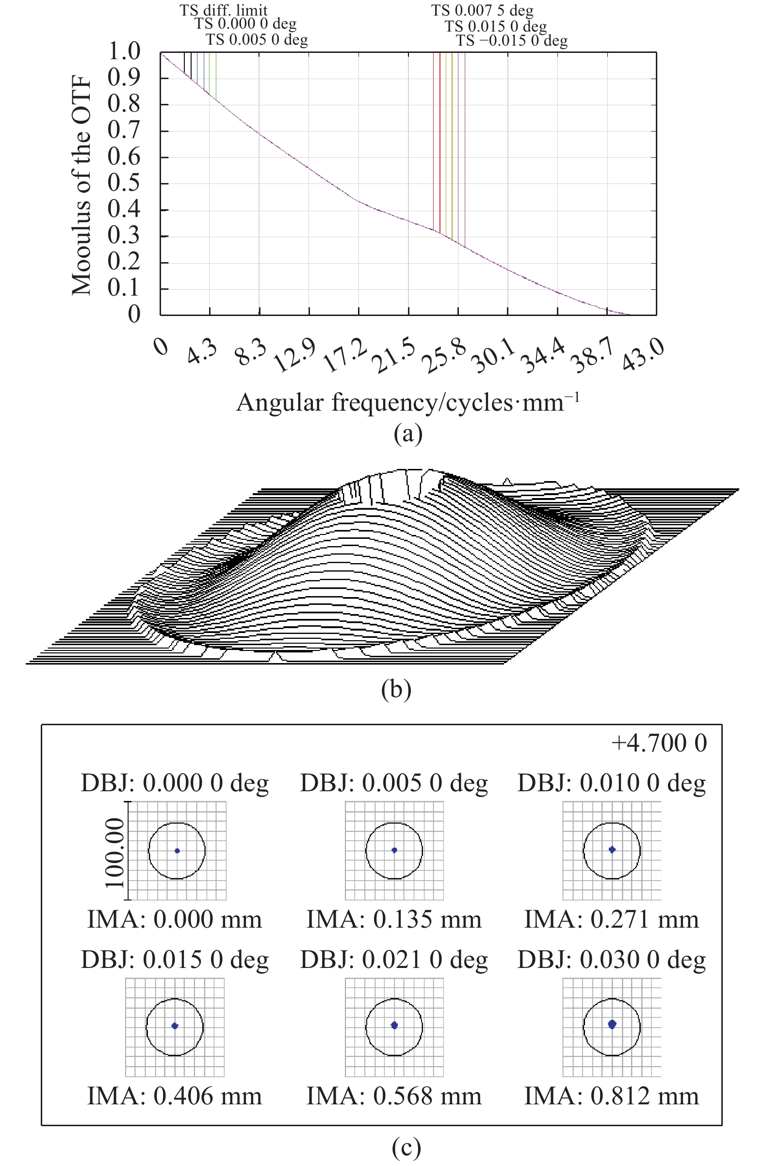
接收光学天线MTF曲线如图6(a)所示,各视场传递函数都达到了衍射极限;系统波前如图6(b)所示,波像差PV值为0.0075λ,RMS值为0.0022λ,λ=4.7 μm;系统点列图如图6(c)所示,各视场几何点列斑均小于艾里光斑。
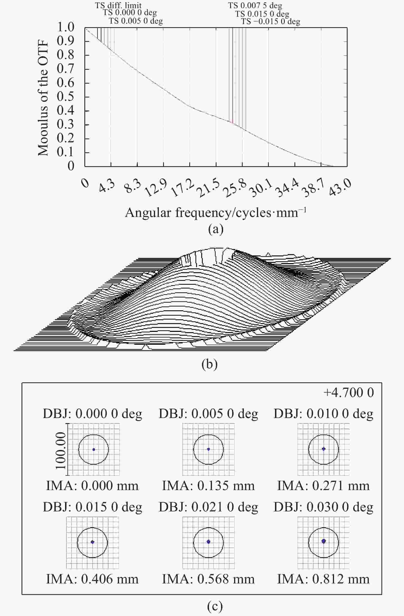
Figure 6. Receiving optical antenna design results. (a) MTF; (b) Diagram of wavefront aberration; (c) Diagram of spot
-
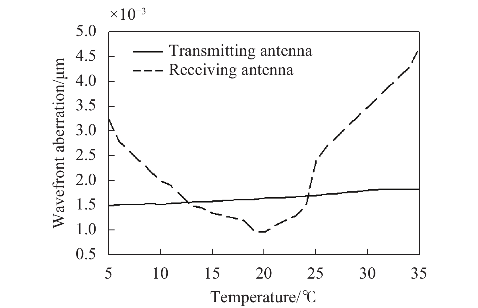
系统要求使用温度为5~35 ℃,设计温度为20 ℃,一个大气压。在结构设计中,主次镜之间、主次镜都采用铸铝合金材料,这样能够保证系统在温度变化时,支撑结构和镜面材料之间无热应力影响,能够保证镜面面型。在光学软件中,采用上述材料在5~35 ℃温度变化时,波前像质分析结果如图7所示。根据温度分析结果可以看出,5~35 ℃温度变化,波前RMS都在0.005λ以内,λ=4.7 μm,基本可以忽略。

Figure 7. Wavefront aberration with temperature
-
光学天线在研制的各个阶段都会对波前造成影响,包括设计残差
$ {\sigma }_{\text{设计}}$ 、加工$ {\sigma }_{\text{加工}}$ 、装调$ {\sigma }_{装调}$ 、环境温度$ {\sigma }_{\text{环境}}$ 等。加工误差主要包括曲率半径、厚度、楔形差、面形误差等,装调误差包括元件倾斜、元件偏心、距离等。在加工误差和装调误差中,除面形误差$ {\sigma }_{\text{面形}}$ 外,都能在光学设计软件公差分析中统一考虑,记为$ {\sigma }_{\text{公差}}$ 。因此,系统波像差可用下式表示[9]:面形误差
$ {\sigma }_{\text{面形}}$ 中又包括反射镜面形误差$ {\sigma }_{\text{反射}}$ 和透镜面形误差$ {\sigma }_{\text{透射}}$ ,若加工面形RMS分别为${\sigma _{\rm{s}}}$ 、${\sigma _{{\rm{s'}}}}$ ,则$ {\sigma }_{\text{反射}}$ 、$ {\sigma }_{\text{透射}}$ 利用以下两式计算:$n$ 为透射面折射率,若系统有$x$ 个反射面,$y$ 个透射面,则系统全部面形引入的波像差$ {\sigma }_{\text{面形}}$ 为:针对发射光学天线和接收光学天线,公差设定为距离±0.03 mm,主次镜和透镜偏心±0.03 mm、倾斜±1′,透镜厚度±0.02 mm,光圈±2 N,楔形差36″。在ZEMAX软件中利用蒙特卡洛法进行500次试验分析,90%以上概率下发射天线和接收天线波像差
$ {\sigma }_{\text{公差}}$ 分别为0.035λ和0.03λ (λ=4.7 μm),分析中选取主次镜间距以及次镜后截距为补偿措施。为降低加工成本,主镜和次镜表面加工面型
${\sigma _{\rm{s}}}$ 为λ1/10(λ1=632.8 nm)。根据现有的加工水平,透镜系统的面形${\sigma _{{\rm{s'}}}}$ 可以做到λ1/20或者更高。由第2节的设计结果可知,发射天线和接收天线的设计残差$ {\sigma }_{\text{设计}}$ 分别为0.0014λ和0.0022λ。由第3.1节温度分析结果可知,5~35 ℃温度变化,$ {\sigma }_{\text{温度}}$ 都在0.005λ以内。将以上数据代入公式(9),可计算得出发射天线波像差RMS值$ {\sigma }_{\text{发射}}=0.055$ λ,接收天线波像差RMS值$ {\sigma }_{\text{接收}}= $ $ 0.051$ λ,均小于0.1λ,仍有较大余量。 -
依照以上公差,对发射光学天线和接收光学天线进行结构设计,确定合理主次镜、光学元件支撑方案,并保证设计结果满足镜面公差要求,进行合理的框架结构,使其满足镜面间距等结构精度要求,此外包括接口设计、杂光抑制。
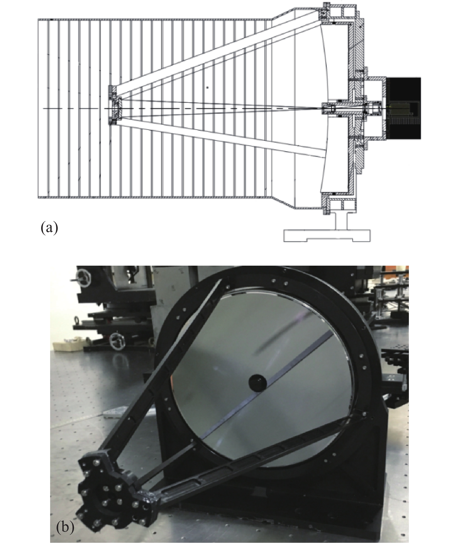
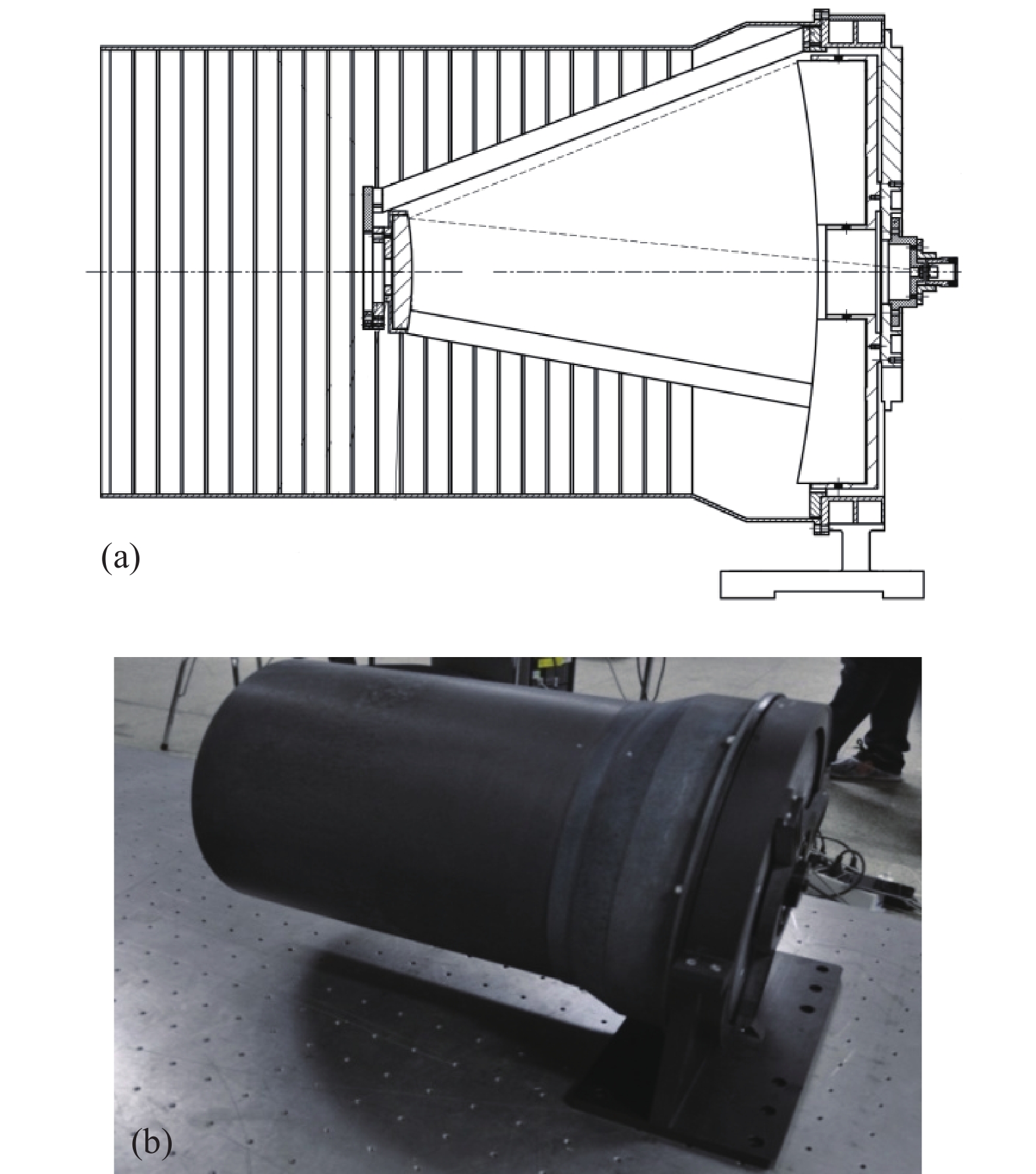
发射光学天线、接收光学天线整体结构与实物图如图8、图9所示,机械结构主要由遮光罩、次镜结构、目镜结构、主镜支撑结构等构成;系统结构、主次镜都采用铸铝合金材料制成。
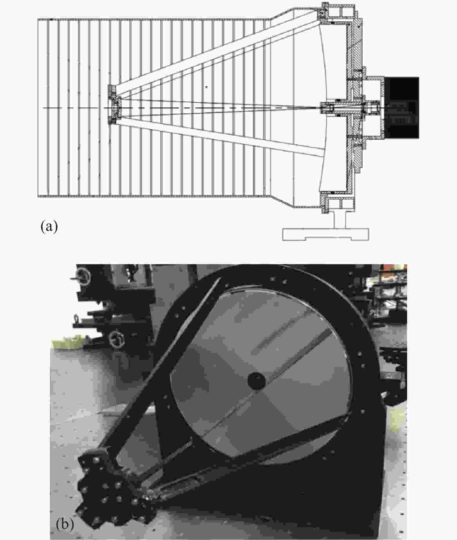
Figure 8. Transmitting optical antenna. (a) Diagram of structure design; (b) Diagram of physical object (without hood)

Figure 9. Receiving optical antenna. (a) Diagram of structure design; (b) Diagram of physical object
由于发射光学天线为中红外折反光学系统,波长为632.8 nm的ZYGO干涉仪无法测量其波像差。采用德国TRIOPTICS公司的光学传递函数测量仪ImageMaster Universal测试发射光学天线的MTF曲线,测试结果如图10所示,发射光学天线实测MTF与理论值最大偏离百分比为9.3%。

Figure 10. MTF testing of transmitting optical antenna. (a) Testing; (b) The measured MTF
接收光学天线在安装滤光片前为反射光学系统,可直接使用波长为632.8 nm的ZYGO干涉仪测量波像差,测试结果如图11所示。测试结果显示,接收光学天线波像差RMS为0.56λ1 (λ1=632.8 nm),换算成实际使用波长4.7 μm,波像差RMS为0.075λ (λ=4.7 μm),满足小于0.1λ的链路计算要求。

Figure 11. Test results of receiving optical antenna wavefront aberration (test wavelength 632.8 nm)
-
文中研制了一套以量子级联中波红外激光器为通信光源的激光通信发射光学天线与接收光学天线,相比近红外激光通信光学天线,系统公差要求更低,降低了研制成本。在利用激光通信能量传输方程进行链路分析的基础上,确定了天线口径、发散角等参数;设计了收发光学天线,进行了详细的波前分析,结果表明在较为宽松的公差下,系统波前RMS值仍留有较大裕量;依据分析所得公差,进行了结构设计,完成了收发光学天线的研制。并对两光学天线进行了光学性能测试,均满足设计要求。
Development of optical antenna for middle infrared laser communication terminal
doi: 10.3788/IRLA20200331
- Received Date: 2020-12-10
- Rev Recd Date: 2021-01-25
- Publish Date: 2021-06-30
-
Key words:
- laser communication /
- middle infrared laser /
- optical antenna /
- wavefront aberration
Abstract: In order to reduce the tolerance of laser communication optical system, save the development cost, and reduce the influence of atmospheric scattering on laser communication link, the middle infrared laser with its wavelength working at the atmosphere window was used as the laser communication light source, and a matching middle infrared laser communication terminal optical system was developed. Firstly, based on the energy link transmission equation of laser communication, the design parameters of the optical antenna, such as aperture and divergence angle, were calculated according to the beam parameters of the middle infrared laser and the detector sensitivity of the receiving terminal, and the wave aberration requirements of the optical transmitting and receiving system of laser communication were given. Then, the design and tolerance analysis of the optical system for the middle infrared laser communication optical antenna were carried out by ZEMAX software, and the system was processed and adjusted to complete the development of the system, and the image quality of the two optical systems was tested. The test results show that the maximum deviation of transmitting optical system MTF from the theoretical value is 9.3%, and the wavefront aberration RMS of the receiving optical system is 0.075λ (λ=4.7 μm), which meets the design requirements. The results show that the difficulty of processing and adjusting optical antenna can be reduced by using the middle infrared laser as the laser communication light source.


 DownLoad: