


-
随着我国航天事业的发展,航天遥感仪器的需求量越来越大,而宽视场是航天相机的一个重要发展方向。在轨道高度一定的情况下增大视场可以增加图像幅宽,在分辨率一定的情况下提高遥感器成像效率,因此,越来越多的航天相机向宽视场方向发展[1]。
航天相机在研制过程中,光学系统装调完成后所形成的像面即是航天相机的像面,像面位置及其与航天相机的相对关系也随之确定。下一工序就是探测器配准,将探测器组件调整到位,实现探测器组件焦平面与像面准确匹配,达到最佳成像质量[2]。像面位置是影响光学系统成像质量的一个重要指标,可以为探测器配准工序的完成提供重要依据,通过实测的像面位置能够快速、准确地完成探测器配准,从而获得较理想的成像质量。
在光学系统装调阶段,对于小视场的光学系统来说,可以通过经纬仪、干涉仪等手段准确地获得系统焦点位置,从而间接获得系统的像面。而对于宽视场的光学系统来说,如果继续采用经纬仪或者干涉仪等手段获取精确的单个视场焦点位置代替整个像面的位置,就会因为视场大导致边缘视场离焦,给探测器配准工作带来难度。
为了解决宽视场光学系统用单个视场焦点位置代替整个像面的位置会导致边缘视场离焦的问题,文中提出了一种光学系统像面测量的方法,搭建了宽视场航天相机像面测量平台,快速、定量、有序地完成了一款宽视场离轴三反航天相机的像面测量。通过测试结果判断光学系统是否装调到位,并为后续探测器配准提供了重要的装调方向。实践证明该方法具有较强的工程借鉴意义。
-
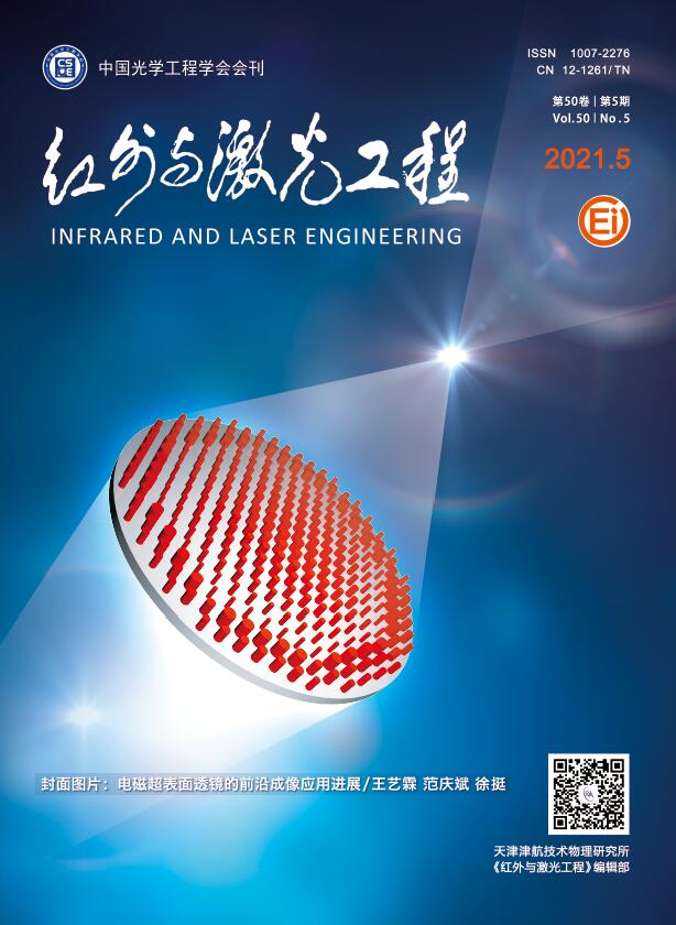
在光学系统装调阶段,使用波像差对光学系统成像质量进行全面的评价。当采用干涉检验法检测系统成像质量时,通常使用自准直检测光路,通过干涉条纹直接得到光波携带的波像差信息[3-4]。图1为装调过程中的自准直光路示意图。
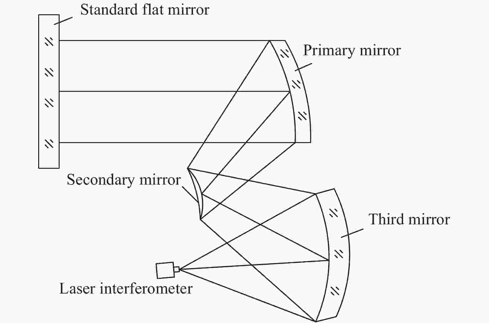
Figure 1. Schematic diagram of self-collimating optical path
自准直检测光路中,干涉仪焦点的位置即为当前视场下光学系统的焦点位置,如果能精确获取全视场下焦点坐标,就可以通过坐标换算得到光学系统像面分布情况。因此,文中采用激光跟踪仪进行坐标测量,运用干涉测量和几何量测量相结合的方法进行像面测量。
激光跟踪测量系统的基本原理是在目标点上安置目标球,跟踪头发出的激光发射到目标球上,又返回到跟踪头,当目标移动时,跟踪头调整方向来对准目标。同时,返回光束为检测系统所接收,用来测算目标的空间位置。激光跟踪测量系统本质上是一种球坐标测量系统。它测量目标点的距离、水平和竖直方向的偏转角,从而得到以跟踪仪测量中心为原点的目标点空间三维坐标[5-6]。
激光跟踪仪的目标球的圆度优于0.003 mm,目标球不锈钢表面经过抛光处理,可以反射光,像面测量时,将激光跟踪仪的目标球放置在干涉仪焦点位置,当目标球球心与干涉仪焦点位置重合时,可以形成干涉条纹。调节目标球的位置使干涉图为零条纹且Power值为零,将激光干涉仪焦点定位到目标球球心上,从而获得焦点的坐标位置。目标球球心定位干涉测量示意图如图2所示。
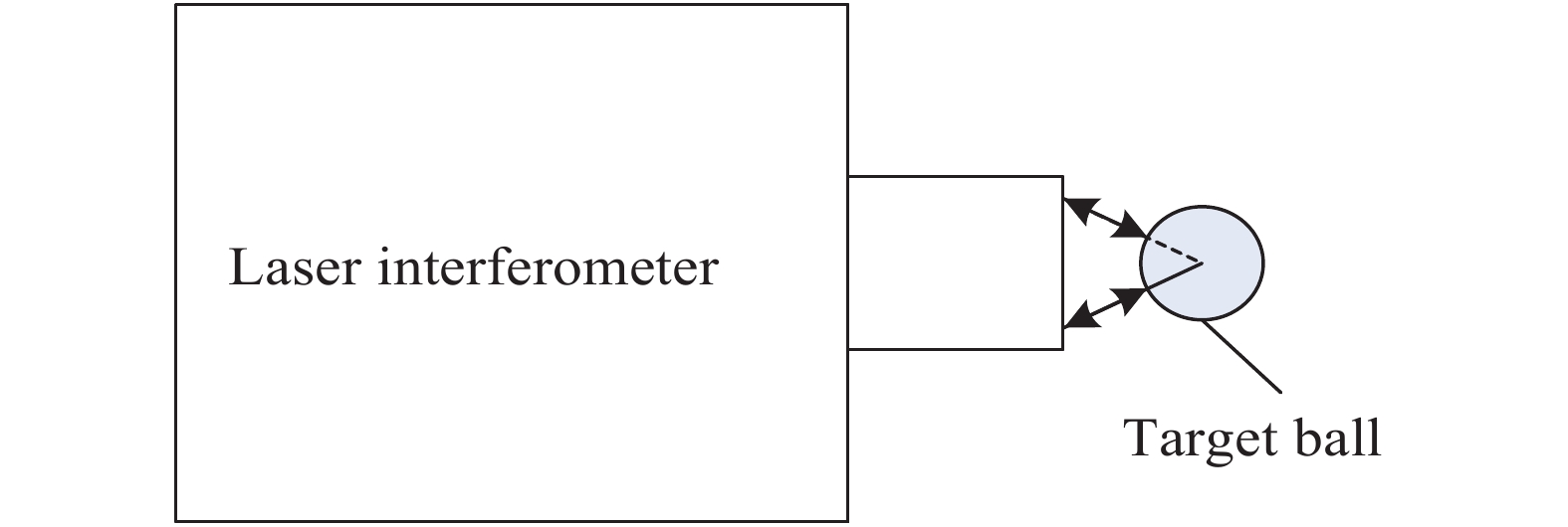
Figure 2. Schematic diagram of interferometry measurement
-
搭建光学系统装调测试自准直光路,在像面测试工作之前完成光学系统的装调,使系统成像质量满足指标要求。像面测量总体流程图如图3所示。
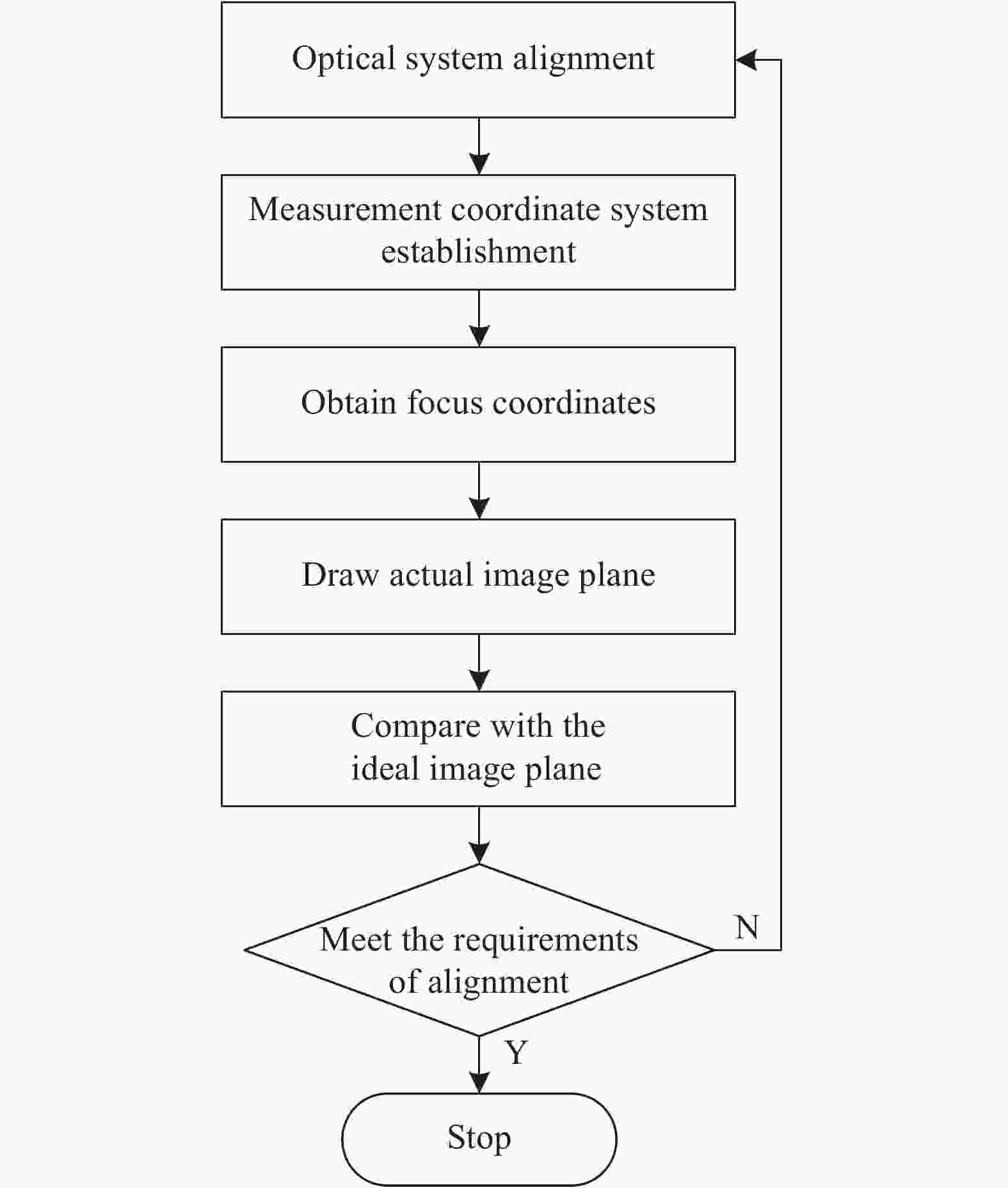
Figure 3. Overall flow chart of image plane measurement
步骤1:根据标准平面镜相对于光学系统的角度关系,调节标准平面镜至中心视场位置。调节激光干涉仪,使全孔径干涉图为零条纹且Power值为零,经过调节后,激光干涉仪焦点与光学系统的焦点重合;
步骤2:使用激光跟踪仪建立测量坐标系,定义坐标原点位置;
像面测量之前,首先要选定激光跟踪仪的安放位置,将激光跟踪仪的主体控制器固定放置在光学系统一侧,可同时探测到像面位置和光学系统,避免不必要的转站。像面测量时,通过测量相机机械基准面和基准点建立测量坐标系。
步骤3:利用干涉法将目标球的球心调至光学系统中心视场的焦点位置,激光跟踪仪记录该点坐标位置;
步骤4:调节标准平面镜和激光干涉仪确定光学系统各个视场的焦点位置,激光跟踪仪记录各个焦点位置的坐标;
步骤5:将获取的各个焦点的空间坐标绘制成像面;
步骤6:利用ZEMAX输出实际镜面面形下光学系统的理论像面。将测量得到的实际像面与理论像面对比,如满足装调要求,则测量结束,如不满足,则对光学系统重新装调,直至满足要求,测量结束。
-
宽视场航天相机属于大视场大口径光学系统,虽然光学设计像差已优化到最小,但由于视场大,轴外像差不可能完全被校正,必然会存在一定的剩余像差[7]。
光学系统的成像质量由主镜、次镜和三镜保证,三块单镜组件最终的装调面形误差影响系统成像质量。另外,光学系统装调不到位也会引入像差。以上原因都会导致实际装调后的光学系统的最佳像面与光学设计的理想像面不完全重合,最佳像面位置是各视场成像质量综合评定的结果。
因此,在光学系统装调阶段搭建像面测量平台测量像面的分布情况,既可以判断光学系统装调是否到位,又可以获得像面相对航天相机的空间位置,为后续探测器组件配准提供装调方向。
航天相机像面测量平台包括激光干涉仪、三维平移台、标准平面镜以及激光跟踪仪,激光跟踪仪由主体控制器和目标球组成。激光干涉仪放置在光学系统像面一侧,标准平面镜放置在光学系统入瞳一侧,激光跟踪仪的主体控制器放置在光学系统一侧。航天相机像面测量平台如图4所示。
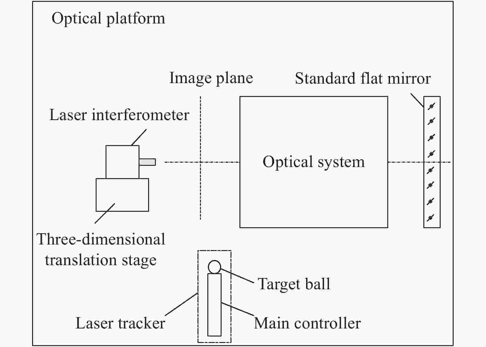
Figure 4. Space camera image plane measurement platform
-
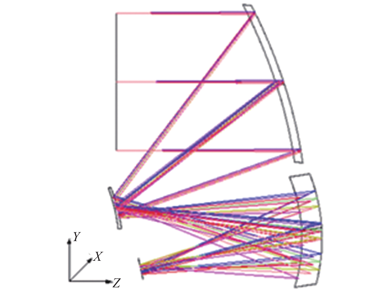
利用光学设计软件ZEMAX完成一款航天相机光学系统的设计,图5为航天相机光学系统结构图,光学系统是由主镜、次镜和三镜组成的离轴三反系统。相对孔径1∶2.4,视场10°×1°,系统像面大小211.59 mm×20.94 mm,其中X、Y和Z为光学坐标系。
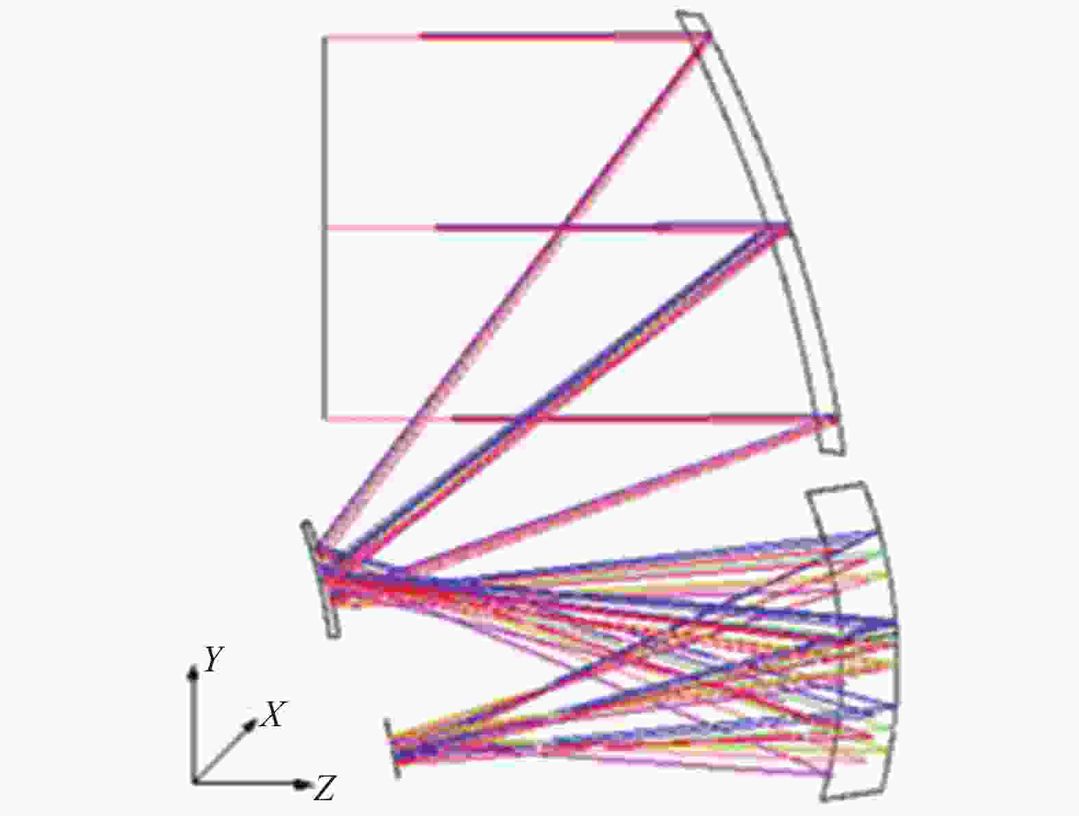
Figure 5. Structure diagram of optical system
首先对单镜组件进行装调,主镜、次镜和三镜组件的面形精度误差RMS分别为:0.061λ,0.050λ,0.059λ (λ为632.8 nm)。之后进行离轴三反光学系统的装调,根据像差理论将光学系统的波像差调整到最小。
-
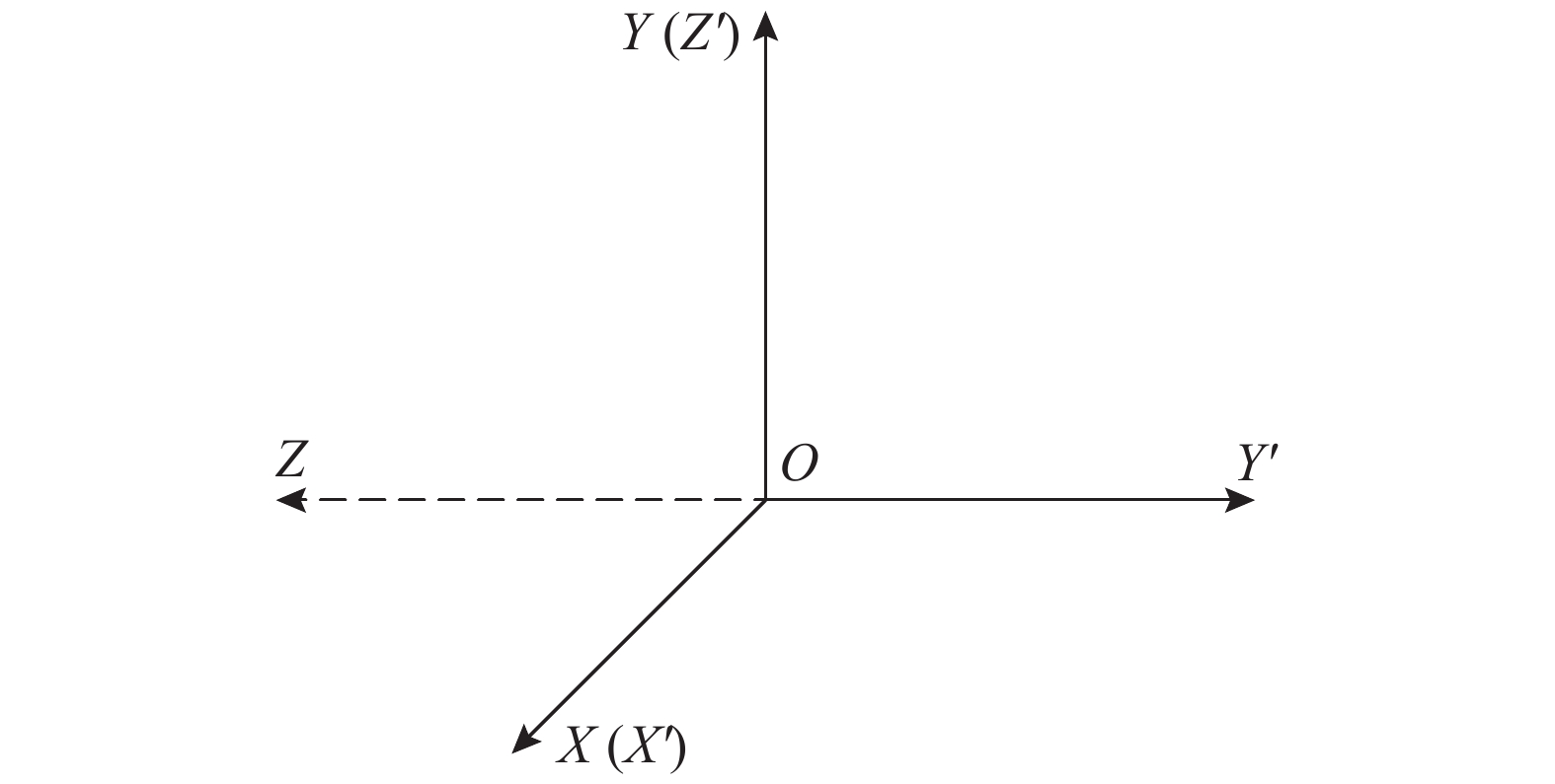
对上述光学系统进行像面测量,建立激光跟踪仪测量坐标系,如图6所示。坐标原点O为相机的安装孔投影到安装面的点,光轴指向探测器为Y′方向,垂直安装面方向为Z′方向,右手定则得到X′方向。

Figure 6. Coordinate system establishment
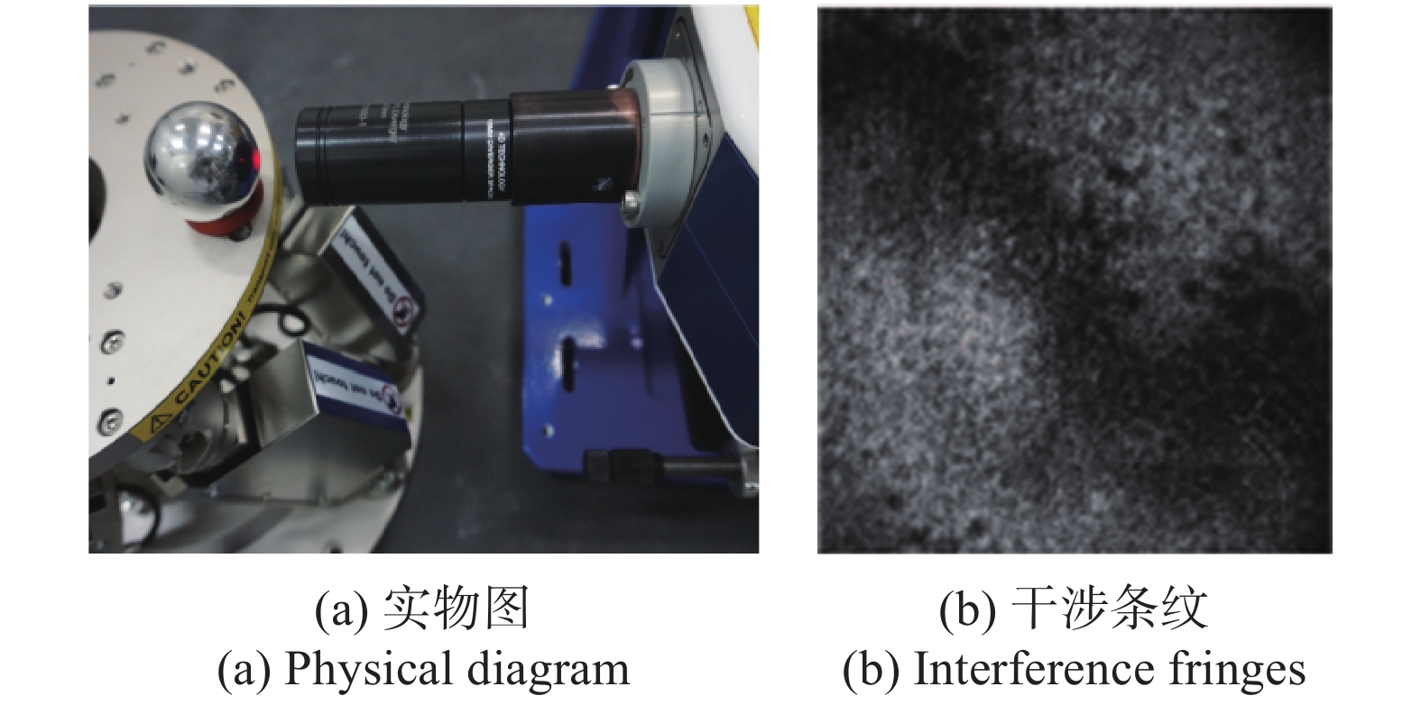
利用激光干涉仪测试光学系统中心视场成像质量,通过调节激光干涉仪,使干涉图为零条纹且Power值为零。将激光跟踪仪目标球固定在高精度六维调节架上,调节目标球,使其球心与激光干涉仪的焦点重合,干涉图为零条纹且Power值为零,此时目标球球心位置为光学系统中心视场焦点,激光跟踪仪记录该点坐标位置。焦点位置测试装置如图7所示。

Figure 7. Focus position test device
通过调节标准平面镜和激光干涉仪确定光学系统各视场的焦点位置,激光跟踪仪记录各焦点位置的坐标。激光跟踪仪获得各视场的焦点空间坐标如表1所示。其中中心视场焦点在测量坐标系下的坐标为X′:−581.068 mm,Y′:−593.755 mm,Z′:141.462 mm。
No. X′/mm Y′/mm Z′/mm 1 −689.141 −593.635 141.747 2 −674.485 −592.964 143.519 3 −660.163 −593.858 141.097 4 −645.744 −593.183 143.007 5 −631.403 −593.99 140.678 6 −617.007 −593.297 142.705 7 −602.635 −594.105 140.465 8 −588.276 −593.318 142.597 9 −581.068 −593.755 141.462 10 −573.882 −594.154 140.392 11 −559.526 −593.317 142.560 12 −545.132 −594.073 140.517 13 −530.763 −593.272 142.803 14 −516.355 −593.936 140.829 15 −501.998 −593.131 143.232 16 −487.578 −593.757 141.337 17 −473.396 −592.911 143.850 18 −674.640 −596.212 134.667 19 −645.853 −596.368 134.144 20 −617.074 −596.505 133.839 21 −588.290 −596.565 133.739 22 −559.488 −596.564 133.716 23 −530.676 −596.466 133.942 24 −501.865 −596.297 134.307 25 −473.220 −596.122 134.966 26 −688.913 −590.404 150.618 27 −660.023 −590.641 149.963 28 −631.310 −590.844 149.527 29 −602.582 −590.903 149.315 30 −573.894 −590.906 149.234 31 −545.187 −590.897 149.417 32 −516.452 −590.792 149.710 33 −487.739 −590.576 150.215 Table 1. Laser tracker test data
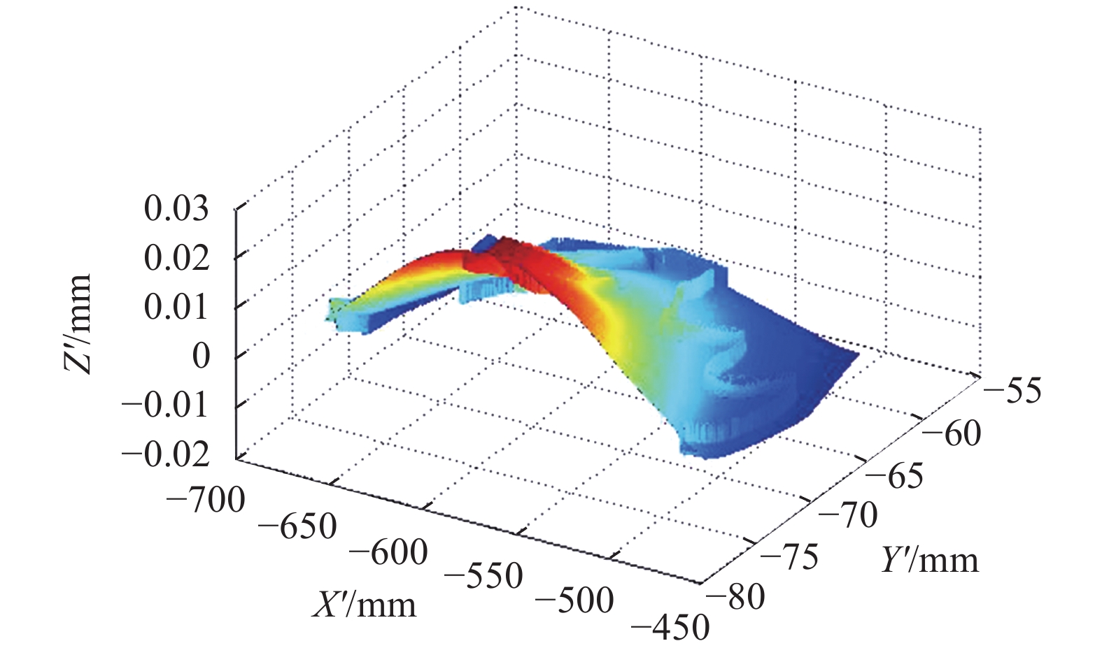
利用MATLAB软件将表1测试的焦点坐标进行像面拟合,拟合出的像面分布情况如图8所示。

Figure 8. Image plane fitting distribution
-
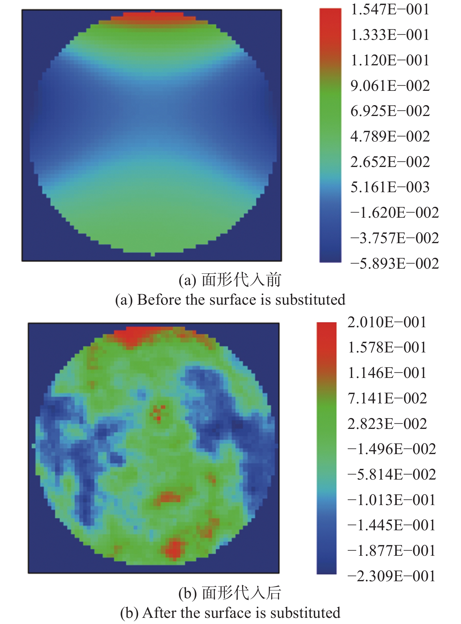
将主镜、次镜和三镜最后装调面形图.dat文件代入光学系统ZEMAX设计文件中,镜子曲率半径、厚度、离轴量等参数均为实测值,图9为面形代入前后光学系统波前图。
代入镜子实际面形后的光学系统,像面的分布情况会发生变化,用ZEMAX分别对各个视场进行分析,得出每个视场在光学坐标系下对应的焦点坐标,如表2所示。
No. X/mm Y/mm Z/mm 1 −104.986 0.000 −31.067 2 −83.912 0.000 −31.060 3 −62.889 0.000 −31.065 4 −41.905 0.000 −31.052 5 0.000 0.000 −31.050 6 41.905 0.000 −31.051 7 62.889 0.000 −31.062 8 83.912 0.000 −31.058 9 104.986 0.000 −31.063 10 −104.986 −10.472 −31.067 11 −83.912 −10.472 −31.068 12 −62.889 −10.472 −31.07 13 −41.905 −10.472 −31.064 14 0.000 −10.472 −31.061 15 41.905 −10.472 −31.063 16 62.889 −10.472 −31.066 17 83.912 −10.472 −31.065 18 104.986 −10.472 −31.065 19 −104.986 −5.236 −31.068 20 0.000 −5.236 −31.055 21 104.986 −5.236 −31.065 22 −104.986 5.236 −31.064 23 0.000 5.236 −31.038 24 104.986 5.236 −31.06 25 −104.986 10.472 −31.059 26 −83.912 10.472 −31.048 27 −62.889 10.472 −31.054 28 −41.905 10.472 −31.034 29 0.000 10.472 −31.024 30 41.905 10.472 −31.033 31 62.889 10.472 −31.052 32 83.912 10.472 −31.045 33 104.986 10.472 −31.056 Table 2. Focus coordinates of ZEMAX ideal image plane
利用MATLAB软件将表2得到的焦点坐标进行像面拟合,拟合出的像面分布情况如图10所示。
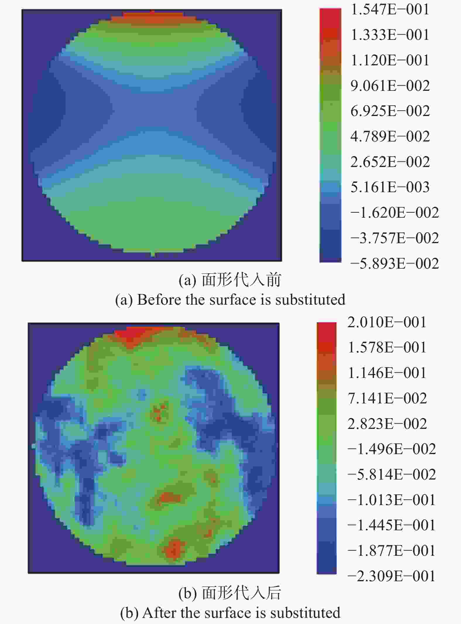
Figure 9. Wavefront diagram of optical system
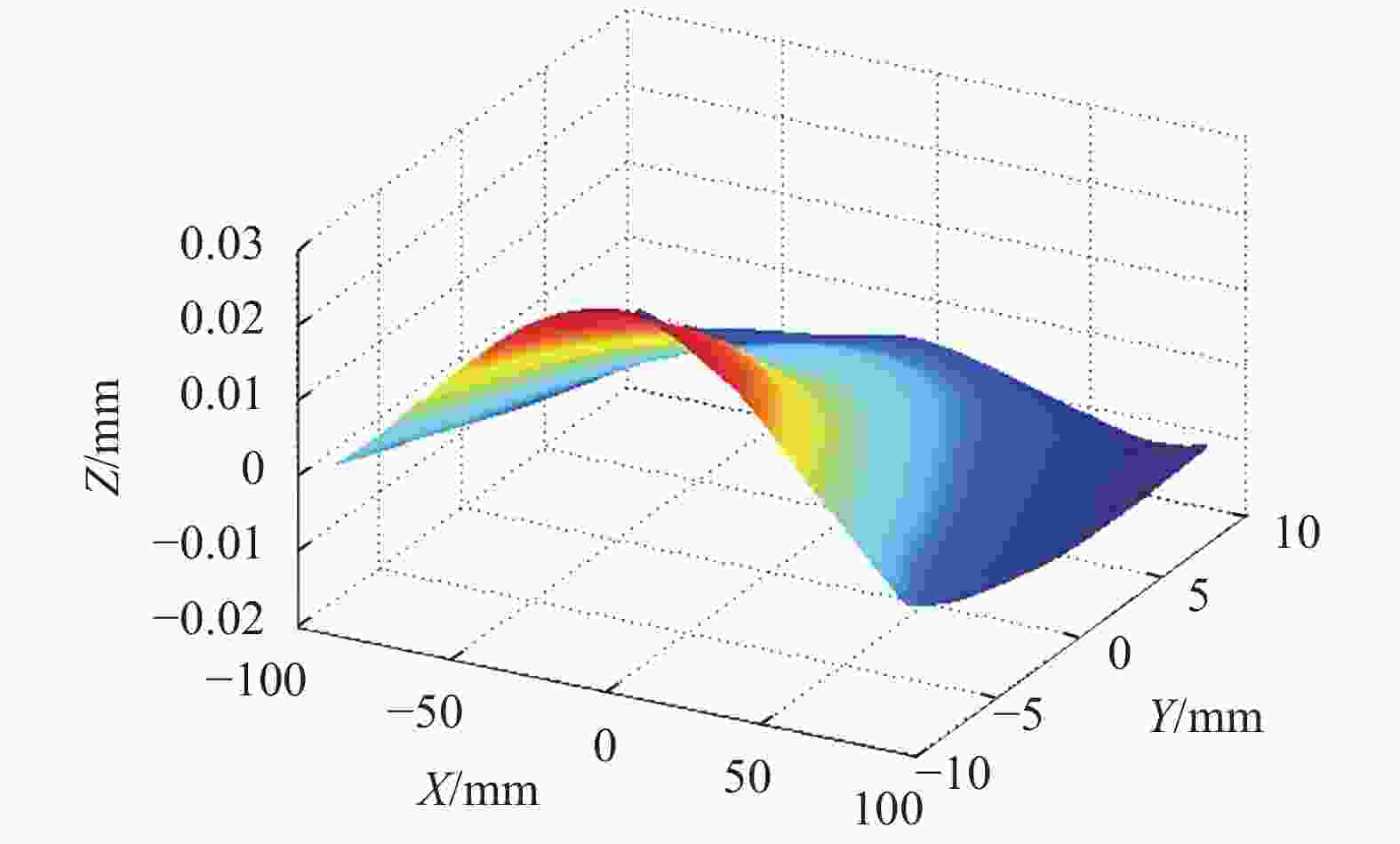
Figure 10. Fitting distribution of the ideal image plane
-
将图8所示的实际像面与图10所示的ZEMAX输出的理想像面进行对比分析。在测量坐标系下,实测像面偏移量分别为Δx:0.12 mm、Δy:0.09 mm、Δz:0.10 mm,实测像面平面度0.049 mm,理论像面平面度0.040 mm,偏差0.009 mm,两个像面形状吻合性较好。根据获得的实测像面位置,在相机总装模型上进行探测器模拟匹配,仿真结果显示,探测器达到最佳位置时,机械接口完全可以匹配。以上测量和仿真结果说明光学系统已装调到位,可开展后续工作。
-
像面测量过程中结合了干涉测量和几何量测量,影响像面测量精度的因素主要是激光干涉仪测量精度、激光跟踪仪的测量精度以及目标球获取焦点位置误差[8-9]。
使用的测量设备有:4D phasecam 6000激光干涉仪,在气流和温度有效控制下,测量精度≤0.01λ (λ为632.8 nm),测量误差μ1≤6.328×10⁻⁶ mm。Leica AT 960激光跟踪仪,利用激光干涉测距,测距精度较高,但激光本身受大气温度、压力、湿度及气流流动的影响,在测试时对此设备进行了大气参数的补偿[10]。在实验室环境相对稳定的情况下,测量距离2 m,距离重复测量精度优于0.007 mm。全量程坐标精度μ2≤0.007 mm。激光跟踪仪的目标球的圆度优于0.003 mm,球偏心≤0.003 mm,干涉法获取焦点时,干涉图调至零条纹且Power值为零,调节引入的倾斜及轴向误差≤0.001 mm,测量误差μ3≤0.004 mm。
综上,采用该方法进行光学系统像面测量,最终分析得到的综合测量精度
${\mu} = \sqrt {{{\mu} _1} + {{\mu}_2} + {{\mu}_3}} $ =8 μm,根据探测器接口设计要求,位移公差为±0.5 mm,测量精度为公差要求的1.7%,完全能满足测量要求。 -
文中提出了一种干涉测量与几何量测量相结合的像面测量方法,该方法实现了光学系统在装调阶段的像面测量,测量精度可以达到0.008 mm。通过此方法,完成了视场10°离轴三反航天相机的像面绘制,并与ZEMAX输出的理论像面进行对比验证,平面度偏差0.009 mm,两个像面形状及位置基本吻合,由此判断出光学系统已装调到位。同时根据实测像面位置,在相机总装模型上将探测器进行模拟配准,指导实际探测器装调工作,提高探测器配准精度和效率。
Measurement technology of image plane of wide-field space camera
doi: 10.3788/IRLA20200336
- Received Date: 2020-09-07
- Rev Recd Date: 2020-12-29
- Publish Date: 2021-05-21
-
Key words:
- optical measurement /
- image plane drawing /
- interferometry /
- off-axis three-mirror reflective system /
- geometric measurement
Abstract: Wide-field and high-quality space camera is the future development direction of payload. Based on the alignment requirements of the wide-field space camera, an image plane measurement method combining interferometry and geometric measurement was proposed. The image plane measurement platform of the wide-field space camera was built. A laser interferometer was used to determine the focal position of each field of view and a laser tracker was used to obtain the coordinates of each focal position in this method. Finally, the image plane was drawn through coordinate conversion and fitting. Image plane measurement error could be controlled within 0.01 mm. Through this method, the image plane drawing of off-axis three-mirror reflective space camera was completed, the system was with a focal length of 1200 mm, a F-number of 2.4, a linear field of view of 10°×1°. The test image plane was compared with the ideal image plane output by the optical design software ZEMAX, the shape and position of the image plane were basically consistent, and the flatness deviation was at 0.009 mm. The test results show that the optical system is aligned in place, and it provides an important basis for the completion of the detector registration process.


 DownLoad: