


HTML
-
遥感器自身的光机背景热辐射是影响系统的探测灵敏度提升的主要因素。随着对微弱目标探测应用需求的提升,要求红外遥感器具备更高的信噪比与灵敏度,需要设计一套能够在低温环境下工作的红外光学系统,从而实现遥感器的高信噪比与高灵敏度[1-3]。低温镜头光学元件的加工与装调一般都在常温下进行,红外透镜常用硅或锗等材料,其热膨胀系数与折射率温度系数较大,在低温下光学元件折射率及支撑结构实际尺寸都将发生非线性变化,进而引起镜头的光轴指向位置、镜子的面形、镜间距及相对焦面位置变化,导致成像质量下降,因此进行光机热耦合仿真分析并进行试验验证十分必要。
文中以某红外遥感器为例,设计了一套具备热卸载功能的透射式低温镜头,镜头工作环境为210 K,在低温镜头设计时,利用光机热耦合仿真分析对低温镜头设计方案进行校核并优化。首先利用有限元分析软件对镜头进行热变形分析,并利用Zernike多项式拟合得到镜子的面形,最终通过光学Zemax软件计算出光学传递函数及离焦量变化情况[4-7],根据仿真结果进一步对低温镜头结构进行优化设计,最终通过在真空罐内进行试验验证仿真分析结果的可靠性。
-
根据使用要求,光学系统工作温度为210 K,据此设计了一套具备热卸载功能的低温镜头,其由六个透镜组成,每片透镜装框后再分别装筒。整个镜头的结构组成主要包括透镜、透镜支撑结构、透镜组件支撑筒及连接件。低温镜头在常温下装调,低温(210 K)条件下工作。
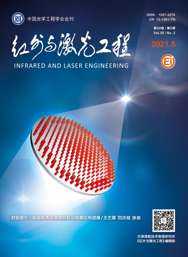
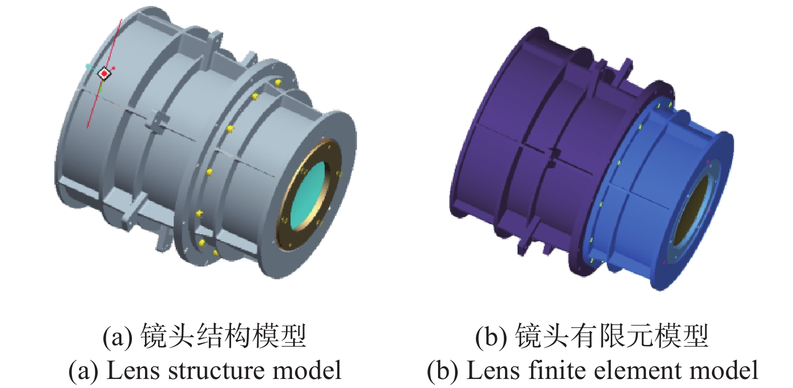
为了保证低温工作环境下光学性能满足要求,低温镜头镜片及支撑结构均采用热卸载结构,低温透镜径向通过环形卸载槽和胶斑两个环节实现热卸载,径向的支撑刚度可通过三种方式调节:一是改变卸载槽的层数,周向长度和轴向宽度来调节;二是改变胶斑的数量,截面积和厚度来调节;三是可以通过拖框安装处的卸载槽进行调节。设计方案示意图如图1(a)所示。
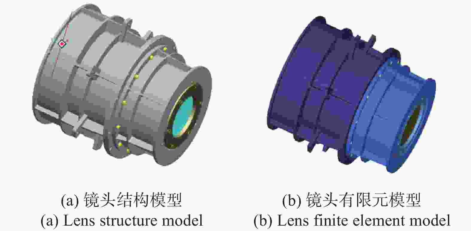
Figure 1. Design scheme of cryogenic lens shows
-
用Hypermesh软件对低温镜头建立有限元模型,结构单元主要为四面体单元、六面体单元及壳单元,一共有37728个节点,29017个网格,如图1(b)所示。
有限元模型里卡片设置时选取293 K作为参考温度,镜头设定工作温度为210 K。低温镜头工作轨道为地球同步轨道,使用Thermal Desktop软件对镜头有限元模型热仿真分析得到模拟在轨状态温度场,加载该温度场,计算低温镜头节点位移。隐藏其他零件,得到镜子节点位移分布云图如图2所示。

Figure 2. Nephogram of displacement distribution of lens nodes
镜片节点的变形包括刚体位移和表面变形,刚体位移会引起光学像发生倾斜与离轴等,表面变形才真正能够反映镜子的面形精度。镜子的刚体位移主要包含沿x、y、z三个坐标系的平移量Tx、Ty、Tz,以及绕三个坐标系旋转的偏转量Rx、Ry、Rz六
个自由度,可利用Sigfit软件对刚体位移变化量进行求解提取[8-9],六片镜子刚体位移求解结果见表1,其中11、12分别代表第一个镜子的正反两个面,其他以此类推。 Mirror number Tx Ty Tz Rx Ry Rz 11 −2.7949E-04 9.9660E-03 −6.0877E-02 7.1514E-06 −1.5074E-06 −5.8983E-07 12 −8.1982E-04 9.3528E-03 −5.6416E-02 7.0429E-06 −1.5240E-06 −5.8931E-07 21 −3.9439E-04 1.2825E-02 −3.4461E-02 1.4481E-05 −2.0520E-06 −7.9392E-07 22 1.6542E-05 1.3727E-02 −2.8960E-02 1.3445E-05 −3.9253E-06 −7.9809E-07 31 3.8012E-04 1.1789E-02 −6.2370E-03 −2.1042E-07 −1.6917E-06 −7.8651E-07 32 −4.8088E-05 1.1473E-02 −1.9305E-03 −7.3894E-07 −2.7398E-06 −7.9127E-07 41 −7.1167E-05 1.1914E-02 5.8549E-02 1.1449E-05 −1.3130E-06 −3.1968E-07 42 −9.3400E-04 1.2348E-02 6.3718E-02 1.1444E-05 −2.6384E-06 −3.2117E-07 51 3.9997E-05 1.1358E-02 6.3480E-02 1.6506E-05 −9.3102E-07 −4.2036E-07 52 −1.0513E-03 1.1771E-02 7.0715E-02 1.5050E-05 −4.2598E-06 −4.1898E-07 61 −1.1529E-03 1.2242E-02 1.1839E-01 8.7089E-06 −4.1861E-06 −1.6503E-07 62 −9.5614E-04 1.2250E-02 1.2138E-01 8.9706E-06 −3.0556E-06 −1.6429E-07 Table 1. Rigid body displacement of lens
-
拟合光学组件面形变化方法的有很多,如Chebyshev多项式、Zernike多项式、Seidel多项式等,其中Zernike多项式用来拟合镜子热应力变形面形时,具有拟合精度高、误差小等优点,并能被Zemax、Code V等光学软件所接受,在此,采用Zernike多项式作为有限元分析与光学分析之间的接口工具。
Zernike多项式的具体表达式为:
式中:
$Z_n^m$ 为Zernike多项式;n为多项式的阶数,n=0,1,···;m为与n相关的序号,其值与n同奇偶,且绝对值小于或等于阶数。根据表1,镜子热变形输出结果包括镜子每一个节点变形前坐标
$\left( {x,y,{\textit{z}}} \right)$ 与变形量$\left( {\Delta x,\Delta y,\Delta {\textit{z}}} \right)$ 。假设镜子表面面形有m个节点,将计算文件数据代入n项Zernike多项式可得线性方程组:令
${S_m}({{{x}}_m},{{{y}}_m}) = {S_m}$ ,${Z_{mn}}\left( {{{{x}}_m},{{{y}}_m}} \right) = {Z_{mn}}$ ,公式(2)可写为矩阵形式:可简写为
$S = qZ$ ,其中$S = {\left( {{S_1},{S_2}, \cdots {S_m}} \right)^{\rm{T}}}$ 为每一个节点变形值;$Z = \left( {{Z_{ij}}} \right)$ 为$m \times n$ 矩阵,$i$ 为节点个数,$j$ 为Zernike多项式的第$j$ 项;$q = {\left( {{{{q}}_1},{{{q}}_2}, \cdots {{{q}}_n}} \right)^{\rm{T}}}$ 为n项Zernike多项式的系数。通常用最小二乘法来获得
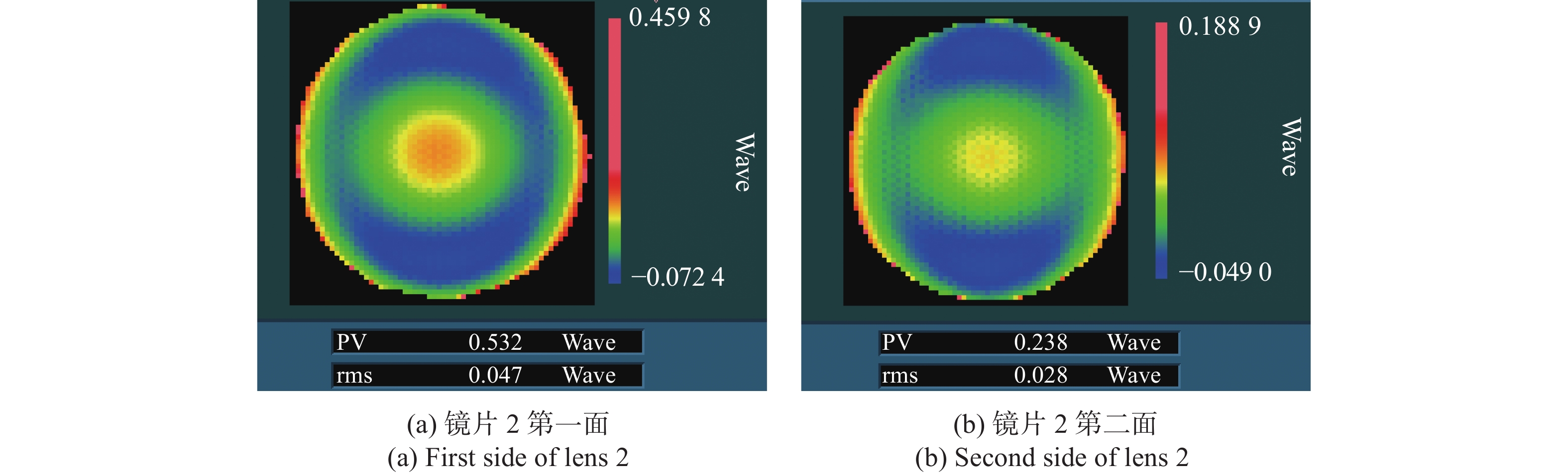
$q = {\left( {{{{q}}_1},{{{q}}_2}, \cdots {{{q}}_n}} \right)^{\rm{T}}}$ 的最小二乘解,将得到的数据代入MATLAB求解Zernike多项式系数,计算时需要去除镜面节点数据的刚体位移。文中仅列出了镜片2的Zernike多项式前37项系数结果,如表2所示,拟合出镜片2面形如图3所示。Zernike number Lens 1 first side Lens 1 second side 1 −0.00039554 −0.00019119 2 −0.00165545 0.00129153 3 0.0006715 −0.0053511 4 0.0005297 0.0011647 5 0.0489164 0.055137 … … … 37 0.00015646 −0.00004436 Table 2. Zernike coefficients of lens 2 fitted at 210 K
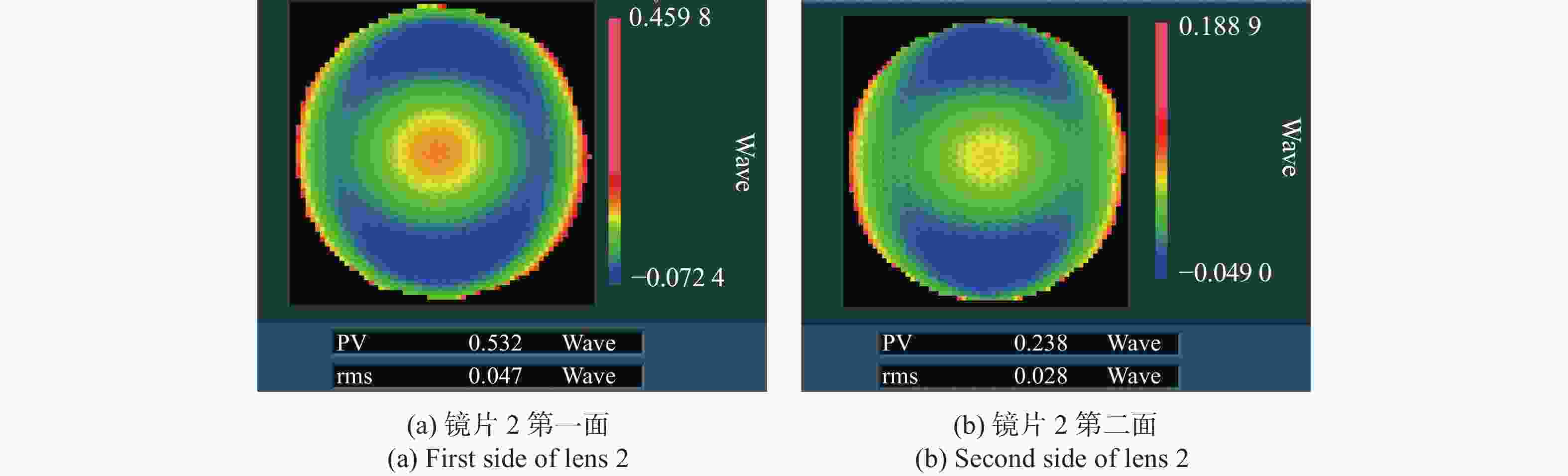
Figure 3. Surface shape diagram of lens 2 (removing rigid body displacement)
该过程需要根据面形计算结果对镜头设计进行反复迭代,直至达到光学设计要求,以上计算结果为数轮迭代后的最终结果。
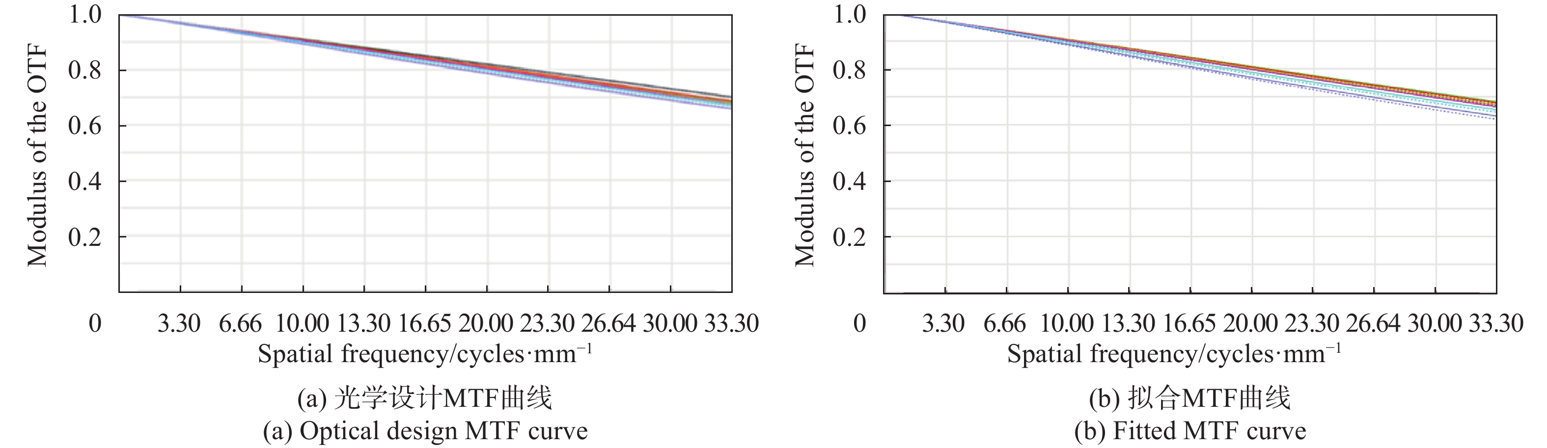
将获得的Zernike系数、刚体位移值等代入Zemax软件中进行分析,可得离焦量与光学系统MTF。计算所得低温工况下离焦量与原始光学设计值分别为70.189 μm与73.56 μm,见表3,低温工况下MTF与原始光学设计值分别为0.6324与0.6586,如图4所示。由此可见,在低温下低温镜头离焦量与MTF均相比原始光学发生了一定的变化。
Category Defocusing amount/μm Theoretical design 73.56 210 K fitting 70.189 Table 3. Defocus of optical system
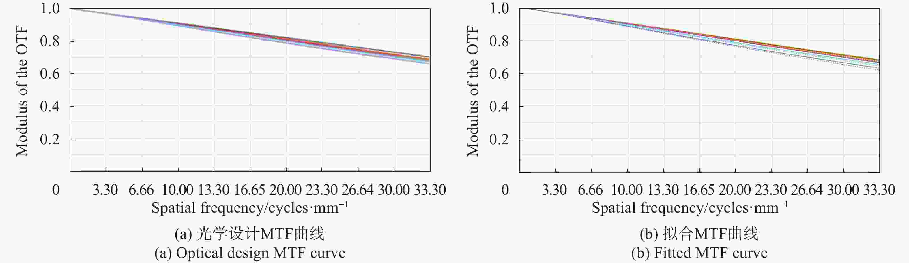
Figure 4. MTF curve of optical system
通过表3与图4可看出,低温工况下离焦量、MTF值利用仿真分析所得结果与原始光学设计值存在微小偏差,主要有以下三个影响因素:一是材料的线膨胀系数设置,在仿真分析时所设置的线膨胀系数为一个固定值,但是有限元模型所加载的温度场并不是恒定的,不同材料的线膨胀系数随着温度变化会随之发生改变,这样设置会造成一定的误差;二是二者加载的温度场有差异,原始光学所赋温度为一恒定值,但是仿真分析所加载温度场为使用Thermal Desktop软件模拟在轨状态温度场;三是建模误差,建立有限元模型时采用不同类型的单元网格进行划分得到的结果也会有微小偏差,且建模时将模型中的安装螺钉、安装孔与小凸台等局部结构特征进行简化处理,这些都会给最终计算结果带来误差,但这些误差属于常规误差,带来的影响均在可接受范围之内。
1.1. 低温镜头结构设计方案
1.2. 低温镜头热变形分析

1.3. 低温镜头光学性能评价


-
低温镜头常温装调及力学试验完成后,需在真空罐中对光学系统性能指标进行验证。单独镜头无法测试MTF等光学指标,需要配合探测器及其他电子学设备测试系统传函来对镜头设计方案进行验证。验证分两个工况进行:一种是相机在真空罐内常温状态进行测试;另一种是在真空罐内将相机光学系统温度控制在210 K进行测试。测试项目为相机分别在常温与低温状态下利用真空罐附带平行光管配合靶标、黑体辐射源进行镜头组件像质测试及焦面位置标定等。参试设备有低温镜头组件、调焦机构、探测器组件、电子学设备、五维调整平台、四杆靶标、平行光管、及地检图采等。
测试产品在真空罐内布置图如图5所示。
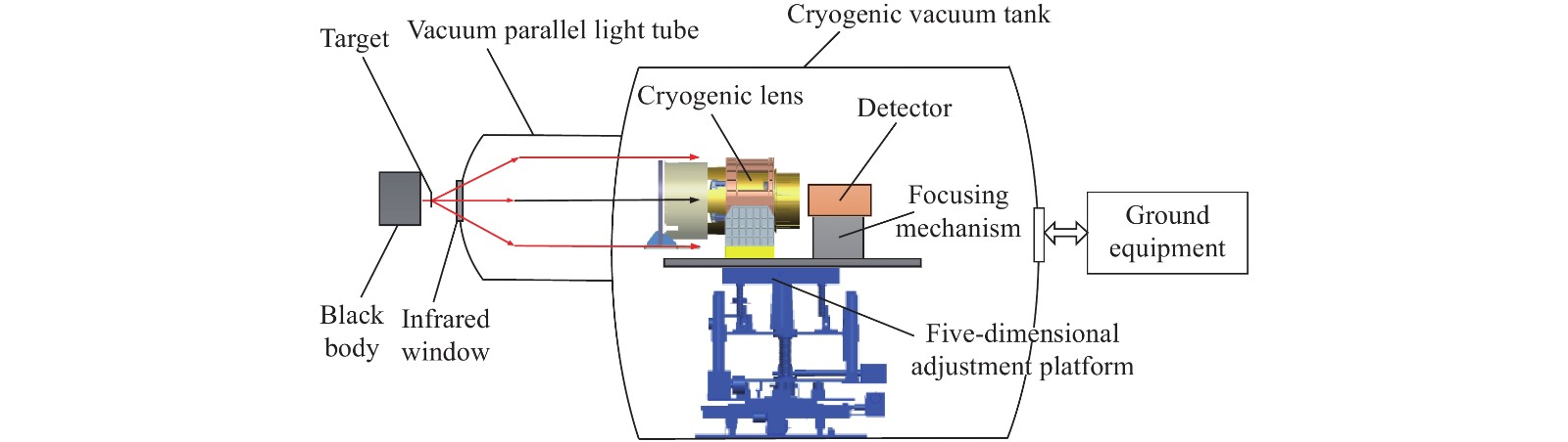
Figure 5. Schematic diagram of test product composition
在规定的试验工况下,通过采用标定过焦曲线的方式进行最佳焦面位置标定与MTF测试,以确定该工况的最佳焦面位置。
(1)最佳焦面位置确定方法:在试验过程中,利用相机调焦机构进行调焦,以MTF测试结果为判断依据,MTF值最大处所对应的位置为最佳焦面位置。调焦机构的调节范围根据离焦量仿真结果并加以足够的安全余量进行确定,该调焦机构设计调节范围为±2 mm,步长5 μm,足以满足实际使用需求。
(2) MTF测试及计算方法:黑体前放置四杆靶标,通过平行光管准直后在像面上成奈奎斯特频率的杆靶标图像,利用公式(4)计算MTF:
式中:V1为亮条纹DN值;V2为暗条纹DN值。
测试准备,相机低温镜头等均放置在真空罐里面,采用独立温控小舱进行控温,如图6所示。各种支撑及其他设备均采取主被动控温措施,使其他产品状态与常温测试状态保持一致,目的是排除这些因素对测试结果的干扰。测试时将四杆靶标放在平行光管的焦点处,首先在常温下进行测试,对四杆靶标进行成像,调节调焦机构调整焦面位置并找寻到MTF值最大处,此时焦面所处位置为常温最佳焦面位置,记录调焦机构位置与MTF最大值。
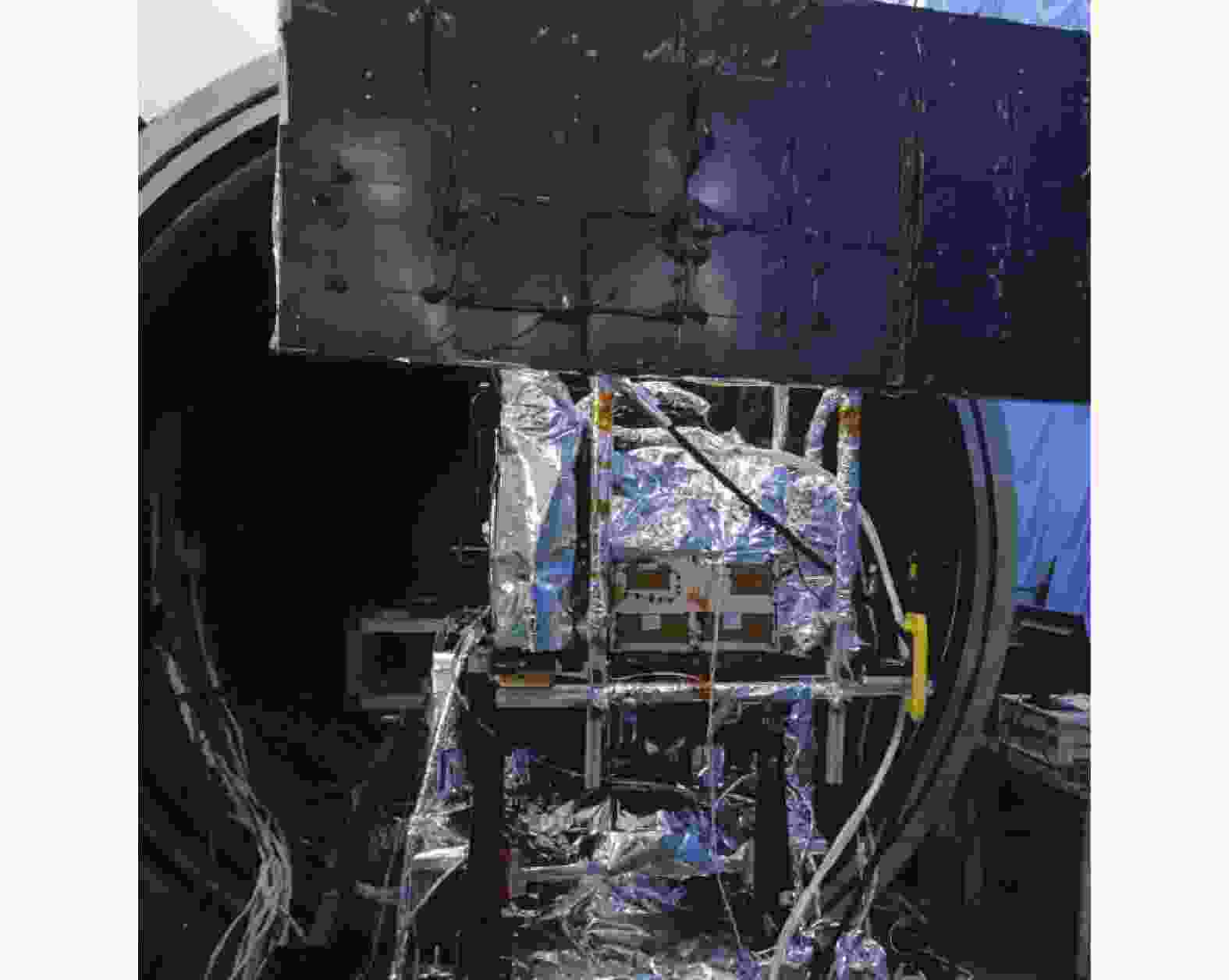
Figure 6. Schematic diagram of tank preparation
相机低温镜头每一个镜片边缘均粘贴有测温热敏电阻,罐内测试时能通过测温热敏读取出镜头温度实时数值,当镜头温度稳定波动在(210±1) K时,对相机成像测试,调节调焦机构找寻到MTF最大值,并记录此时焦面位置与MTF值,此时调焦机构在低温真空罐带动焦面探测器组件寻找到最佳焦面位置时所调节的数值即为低温测试的离焦量。
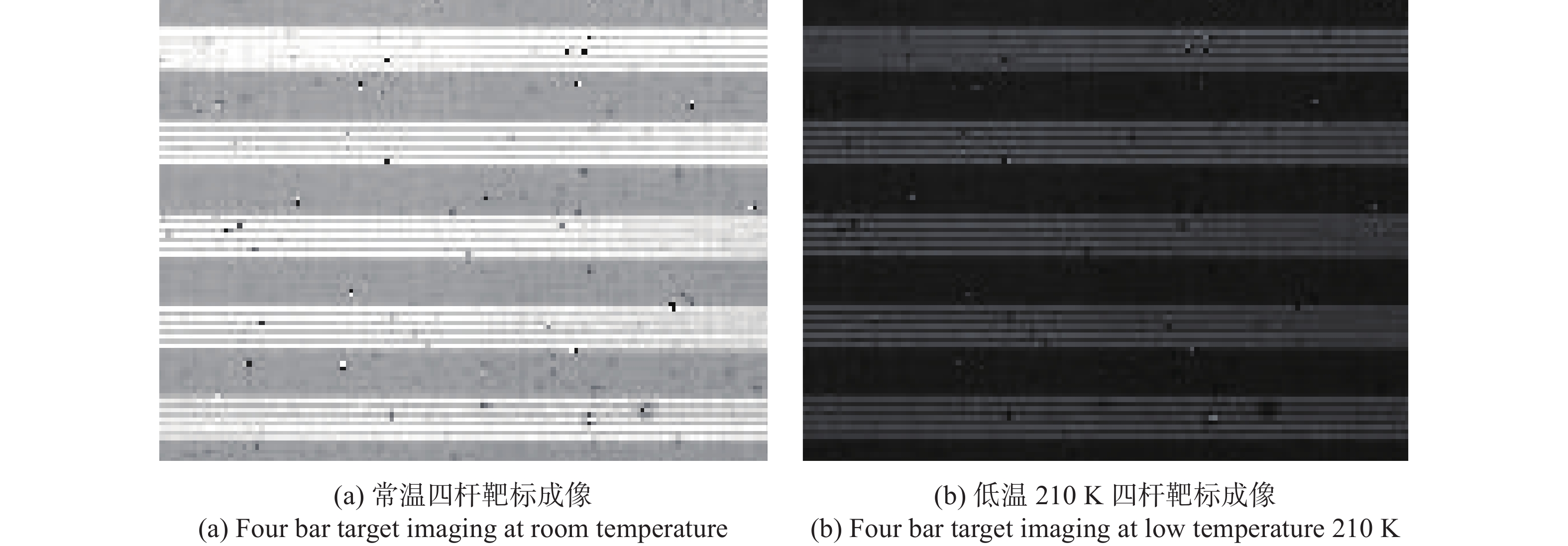
常温与低温下测试MTF时四杆靶标成像如图7所示。

Figure 7. MTF test diagram
根据图7试验结果,常温下测试系统MTF为0.2861,低温210 K测试系统MTF为0.2854。
理论设计、拟合仿真及试验结果见表4。
Working condition MTF Defocusing amount/μm Theoretical design (210 K) 0.6586 (Cryogenic lens) 73.56 Simulation fitting (210 K) 0.6324 (Cryogenic lens) 70.189 Room temperature test (293 K) 0.2861 (System) − Low temperature test (210 K) 0.2854 (System) 71.2 Table 4. Theoretical design, fitting simulation and test results
通过表4,拟合仿真结果表明低温环境下镜子面形变化将导致红外光学系统离焦量与MTF发生变化,设计低温镜头时需要充分考虑低温环境对光学系统带来的影响;低温测试光学系统离焦量与拟合仿真结果比较吻合,离焦量误差为1.44%,低温测试在最佳焦面位置处MTF值与常温MTF测试结果相比仅退化了0.2%,均在可接受范围之内。


-
文中以某具备热卸载能力的红外低温镜头为例,采用光机热多场耦合分析手段,对其在210 K低温工作环境下光学评价指标MTF及离焦量进行分析,并搭建了常温与低温测试系统,开展了实测试验,对镜头在常温与低温下光学评价指标试验验证。从对比分析结果中可以看出,低温环境对光学系统产生的影响不可忽视,但是通过耦合仿真优化,设计结果与试验结果比较接近,可认为对低温镜头进行光机热耦合仿真方法合理可行,对于低温镜头的设计具有指导意义,对后续其他类似产品的研制有很好的工程价值。

 DownLoad: