


-
激光雷达(LiDAR)测深技术近些年来在地形勘测、水深测试、军事侦查等领域应用广泛[1]。激光能量测量属于激光技术的重要组成部分,也是研发激光器的基本工作,而在激光能量测试实验中,激光的发射能量大小直接影响测试的深度和精度。
自1958年,C.H.Downes和A.L.Sholo团队将微波量子放大器应用到光谱范围,提出第一代激光器以后,人们将光热效应应用在光度计量领域,提出一种绝对辐射计,这种测量仪器可以探测0.1~100 mW的激光功率[2]。1960年,H. MAIMAN等人研制了第一台红宝石激光器,它也是一种大能量脉冲固体激光器,可以发射ns级脉宽的激光,他们在激光能量测量时,选用了流水功率计,可以完成对50 W以上的连续激光功率测量[3]。在同时期,还出现炭锥能量计[4] 和体吸收能量计[5],这类能量计都是根据热电效应,热电元件会将吸收到的光能转化为热能,根据温度变化来计算激光能量,还可以通过温度变化导致的次级效应来测量激光能量。
1962年,R.N.Hall等人创造了半导体激光器,它是通过注入电流的方式来泵浦产生激光,它的激光波长范围覆盖了可见光到红外光的所有范围,最高输出光脉冲能量可达50 W(脉宽100 ns)[6]。在研发半导体激光器的同时,为了计算它的发射激光能量,美国人研发了2CU4401型和HP型硅光二极管,这是第一次通过光电法进行激光能量的测量,以光电式探测器或者半导体光电二极管作为传感器件的光电式探测器[7],光信号转换为电信号后,电信号经过电荷积分器得到与输入光脉冲能量成正比的电压信号,从而测量出激光能量值。同期出现的产品包括:连续毫瓦激光功率计、JCS-1型数字式脉冲激光峰值功率计、光电能量计[8]。而国内在1970年开始研究光电式激光能量计,并研制出LEM-1型能量计,可以完成对毫秒脉冲的激光能量测量。
在20世纪末期,Laser Precis Son公司用热电堆或热释电材料作为传感器的吸收性探测器,即让激光与吸收体充分作用,再用热电传感器测试吸收体的上升的温度,从而得到吸收体的热量值,即为激光能量值,并研发出RK-3230型热释电辐射计和RS-3900型电校准热释电辐射计[9]。
笔者从项目实际需求出发,针对不同深度的水深完成激光能量测量受到能量计的量程限制,以及无法兼顾水上通道红外波段的强激光能量以及水下蓝绿波段的弱激光能量测量的问题,有针对性地对1 064 nm和532 nm的脉冲激光能量做出测试。
文中在光电法测量激光能量的基础上,针对1064、532 nm的激光能量,设计了一套激光能量计算方法。该方法的理论建立在带宽大于1 GHz的高速光电探测理论之上,虽然不同的探测器的放大增益、灵敏度以及波长响应不同,但是光电转换理论是一样的,所以文中方法不受探测器种类限制,不受能量计量程限制,显得更加灵活。
-
激光能量测试的原理主要包括两个部分:高速光电探测和激光参数测量。高速光电探测原理证明该激光能量测试方法的可行性,而脉宽测试原理主要保证该方法的真实性。
激光能量测试方法的整体流程如图1所示。
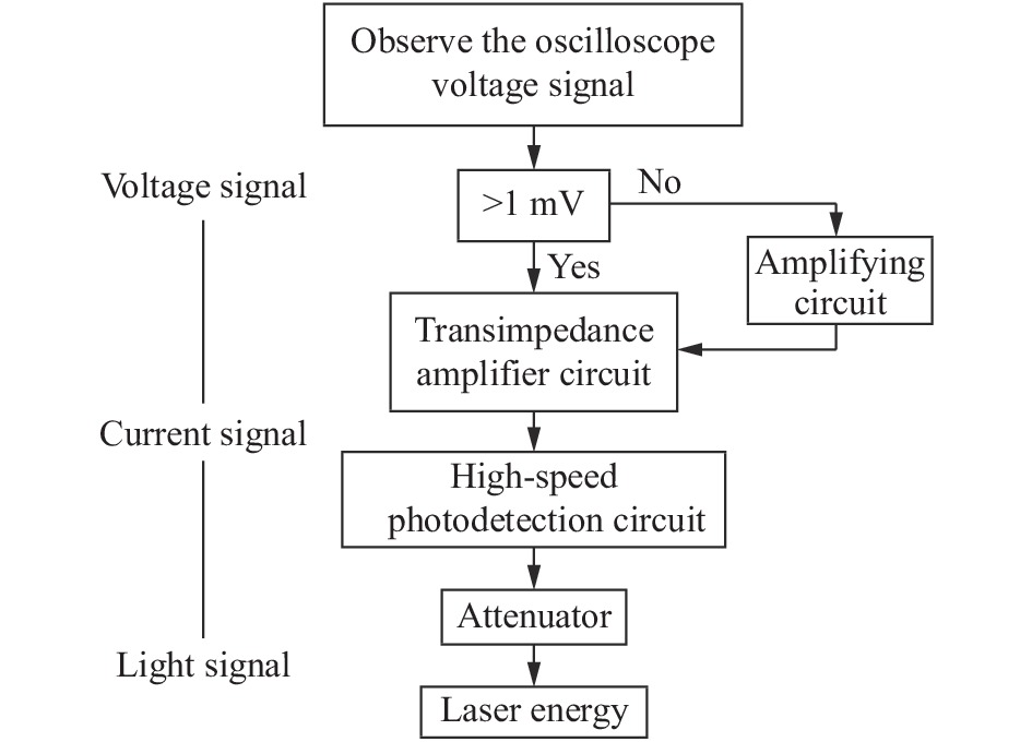
Figure 1. Design flow chart of laser energy test
首先,观察接收到的光电压信号大小,如果光电压信号<1 mV,需要外接放大电路,再进行跨阻放大逆运算得到光电流信号。如果电压信号>1 mV,可直接经过跨阻放大电路的逆运算计算出光电流大小。
其次,光电流经过光电检测电路的逆运算得到光信号。因为射入光电探测器靶面的激光已经经过了光学衰减器的衰减,通常衰减精度是其衰减量的±0.1倍,所以经过光电探测器靶面探测到的激光能量还需乘以衰减倍数之后才等于激光发射能量。
最终,观察发射激光的参数与可调激光器设置参数是否保持一致确认该测试方法的真实有效性。激光能量测试的整体指标见表1。
Experimental parameters Main index requirements Voltage value displayed
by the oscilloscope> 1 mV One-stage voltage amplifier circuit Voltage gain more than 10 times Transimpedance amplifier circuit Gain 2 K, bandwidth 1 G High-speed photoelectric
detection circuitAPD conversion gain 105 V/W
PMT conversion gain 102-107 V/WAttenuator 1-99 dB Table 1. Overall index of laser energy test[10]
-
光电探测技术是把不便量化分析的光信号转化为可在示波器中可见的电信号,然后根据后续信号处理电路所需的电压值进行放大处理。
文中设计的高速光电探测电路(见图2)由APD或PMT、跨阻放大器(TIA)、比较器、电流基准、输出驱动等模块构成[10]。

Figure 2. Circuit structure diagram of high-speed photodetection
该电路的工作原理为:改变可调激光器的泵浦能量,当光脉冲信号照射到探测器光敏面上,实现光信号到电流信号的转换,电流信号输入TIA电路,实现电流信号到电压信号的转换,TIA输出的电压信号接入比较器,比较器充当模数转换器(ADC)的功能,所以当TIA输出达到比较器翻转阈值时,比较器就会翻转一次,从而表示光信号的探测结果[11]。
根据光电系统辐射源的发光强度、传输介质和目标的传输及调制损耗、接收光学系统接收孔径的限制及反射吸收等损失的影响,可以测试出入射到探测器光敏面上的实际辐射能量[12]。
-
激光最主要的参数包括:脉宽、重复频率、泵浦功率。脉宽t是指激光时域脉冲上升时间tr和脉冲下降时间tf到它的50%的峰值功率点之间的时间间隔[13]。重复频率是指激光在某个时间周期内脉冲信号触发的次数,而泵浦功率主要表示脉冲信号所搭载的能量大小。
对于不同的脉冲激光的上升时间量级和时域量程,根据对测试结果的不同要求,采用的测试方法有两类[14]:(1)直接测试法,采用快速探测器,将光信号转换成电信号,通过存储示波器记录其波形;(2)采用相关函数将时间函数转换成空间函数。利用标准延迟器和光速c换算出其时域脉冲波形参数,并依据脉冲激光的时域波形测试获得脉冲宽度t等的时域参数[15]。
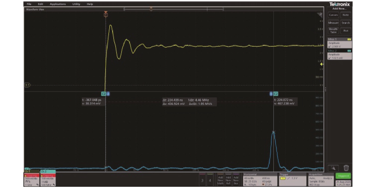
文中采用直接测试法,发射激光的同步信号如图3所示。

Figure 3. Comparison of the synchronization signal and echo signal of laser emission
脉冲激光的参数量值的测试是否准确,将直接影响最终辐射模拟光源峰值功率的结果,是影响最终测试结果的一个重要因素,也是对测试结果进行不确定性评估的一个重要分量。
-
对于波长为1064 nm的激光能量测试,文中使用的是北京科扬公司的KY-ARPM系列的APD模块,它的内部集成了低噪声宽带跨阻放大器,输入阻抗为50 Ω,这种封装方式可以直接输出电压信号,也可以减少暗电流、自然光以及热电阻带来的噪声干扰[16-17]。
按照APD探测器的光电转换和跨阻放大过程,可以测试出激光能量,如公式(1)所示:
式中:J*为发射激光能量;
$ \eta $ 为激光衰减倍数;D为激光脉宽;V为示波器探测到的电压;Gain为APD探测器的光电转换增益。(1) APD激光响应度和激光波长关系见图4,针对波长为1064 nm的激光,对应的响应度大概在0.3 A/W,而文中设计使用的APD模块峰值响应度为0.5 A/W,此时它的转换增益为105 V/W,说明对于1064 nm,模块的转换增益Gain为:

Figure 4. Relationship between APD laser responsivity and laser wavelength (M=1)
(2)以图5测试结果为例,示波器探测到的电压V在0.552 V,激光功率W为:
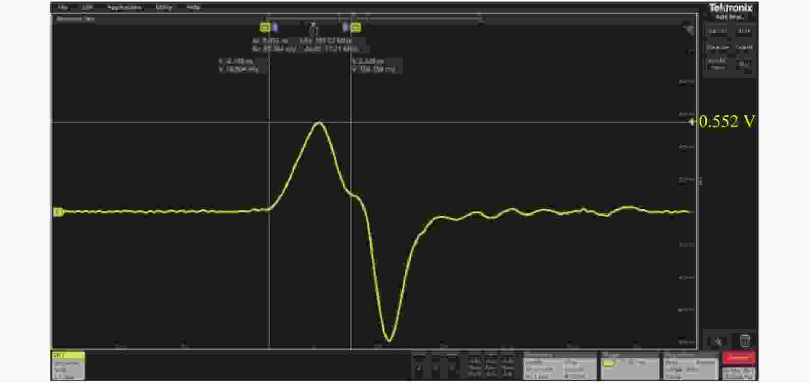
Figure 5. Energy meter test results
(3)激光脉宽D=5 ns,激光能量J为:
测试前,首先确认APD的阈值,防止接收到的回波信号处于饱和状态。再按照激光能量和激光功率的关系设置好对应的脉宽,经过测试电路的放大后,选用60 dB叠加30 dB的衰减片,使激光能量衰减9×10⁸倍。
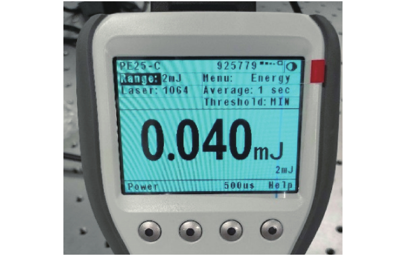
(4)真实激光能量J*为:
使用能量计测出的激光能量是0.040 mJ(见图6),因为很多激光器的最小量程为2 mJ,而显示数值只能到mJ级。实验结果证实,文中方法可测试出1064 nm的激光能量。
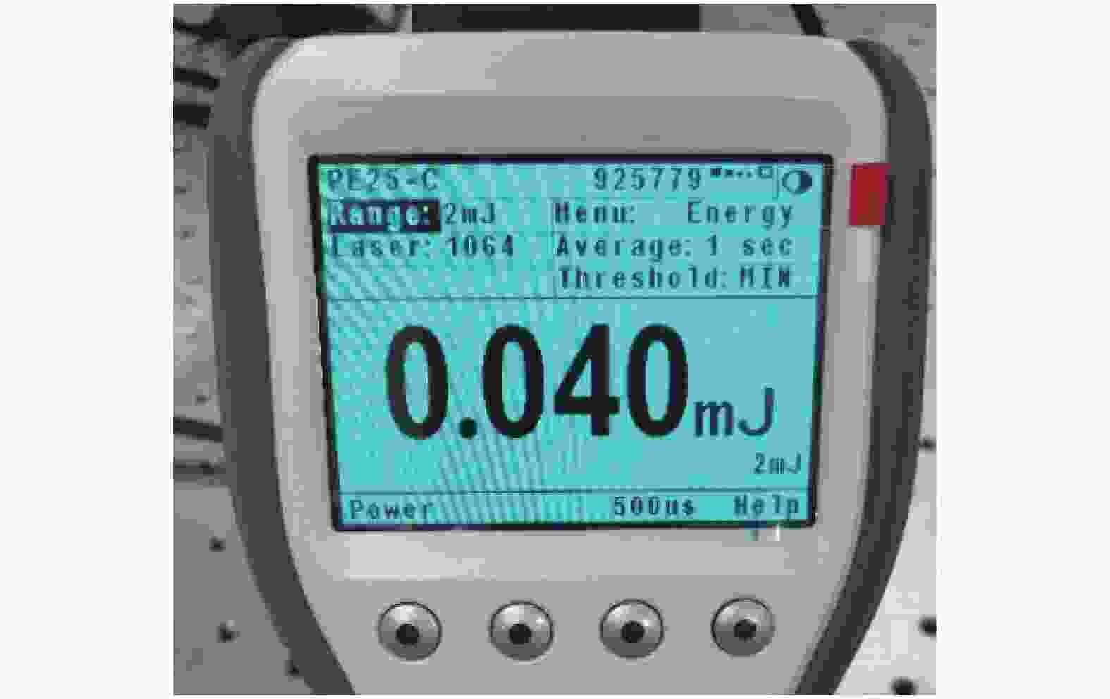
Figure 6. Voltage signal received by the APD module
-
对于波长为532 nm的激光能量测试,文中使用的是日本滨松公司的H11526系列的PMT模块,它的重复频率为10 kHz,内部高压电源可外接一个滑动变阻器来改变模块的控制电压,方便实验时调整控制电压来改变PMT增益。实验过程和APD很类似,最大的不同之处在于PMT需要信号发生器对其进行时序控制,并且PMT的增益会随着控制电压实时改变。一般控制电压为0.4~0.9 V,可以控制放大增益在103~107。因为此PMT模块为电压输出型模块,内部集成的跨阻放大电路增益D为0.1 V/μA和1 V/μA。
按照PMT探测器的光电转换和跨阻放大过程,可以测试出激光能量,如公式(2)所示:
式中:M为波长532 nm时PMT的激光响应度;D为激光脉宽;Gain1为PMT的光电转换增益。
实验选用了OPA847芯片的放大电路,该电路的偏置电流很低,带宽为4.2 GHz[14]。放大电路采用±6.5 V供电,可以将电路输入口接上PMT模块的输出端,电路的输出口接入示波器。
以图7测试结果为例,示波器探测到的电压V为0.291 V,控制电压为0.9 V,PMT的增益为5×10⁶,PMT响应度与波长关系见图8,对应532 nm的响应度为40 mA/W。PMT模块的跨阻放大增益为0.1 V/μA,脉宽为5 ns。选用60 dB叠加60 dB的衰减片,将激光功率衰减了9×10¹¹倍。
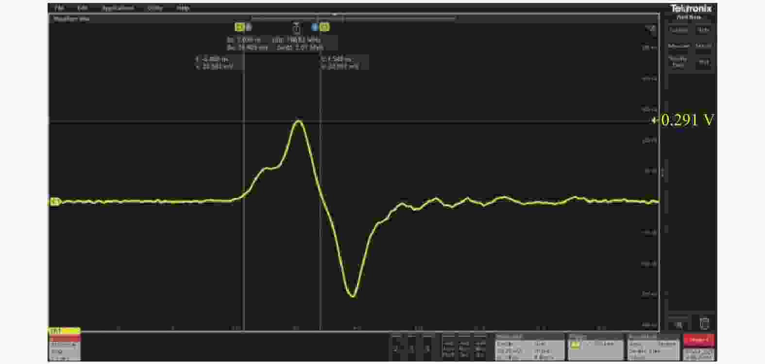
Figure 7. Relationship between PMT responsivity and laser wavelength
(1)与文中第2.1节中对APD的激光能量测试类似,J为:
(2)真实激光能量J*(见图9)为:
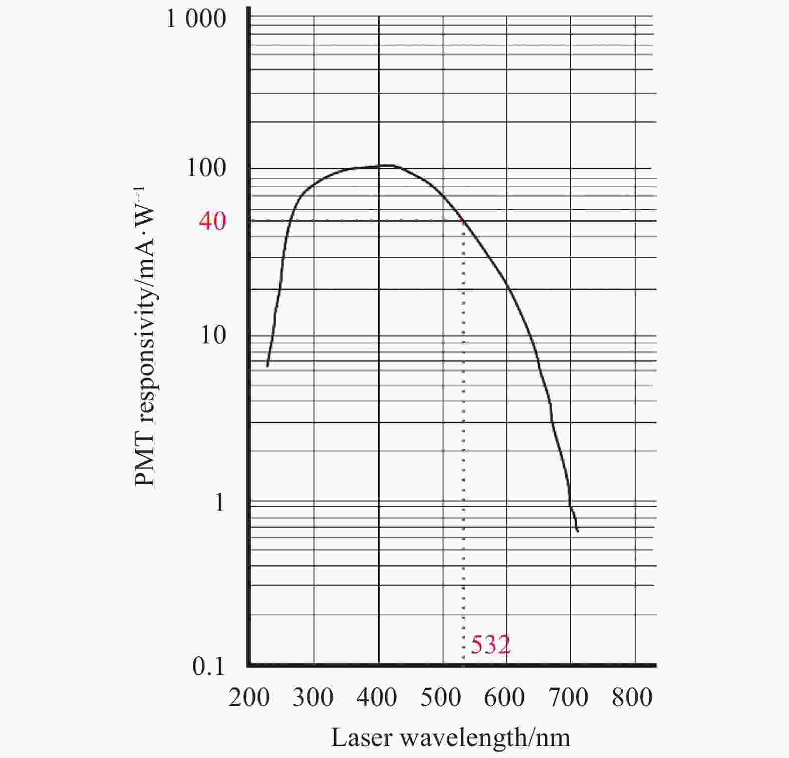
Figure 8. Energy meter test results
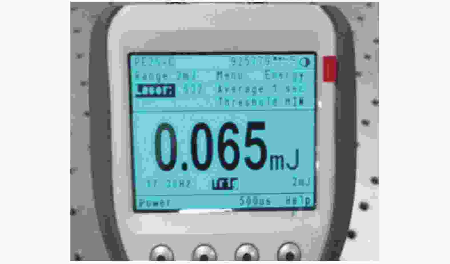
Figure 9. Voltage signal received by the PMT module
能量计测出激光能量值为0.065 mJ,和文中方法测试结果一致,再一次证实所提方法可用于波长532 nm的激光能量测试。
-
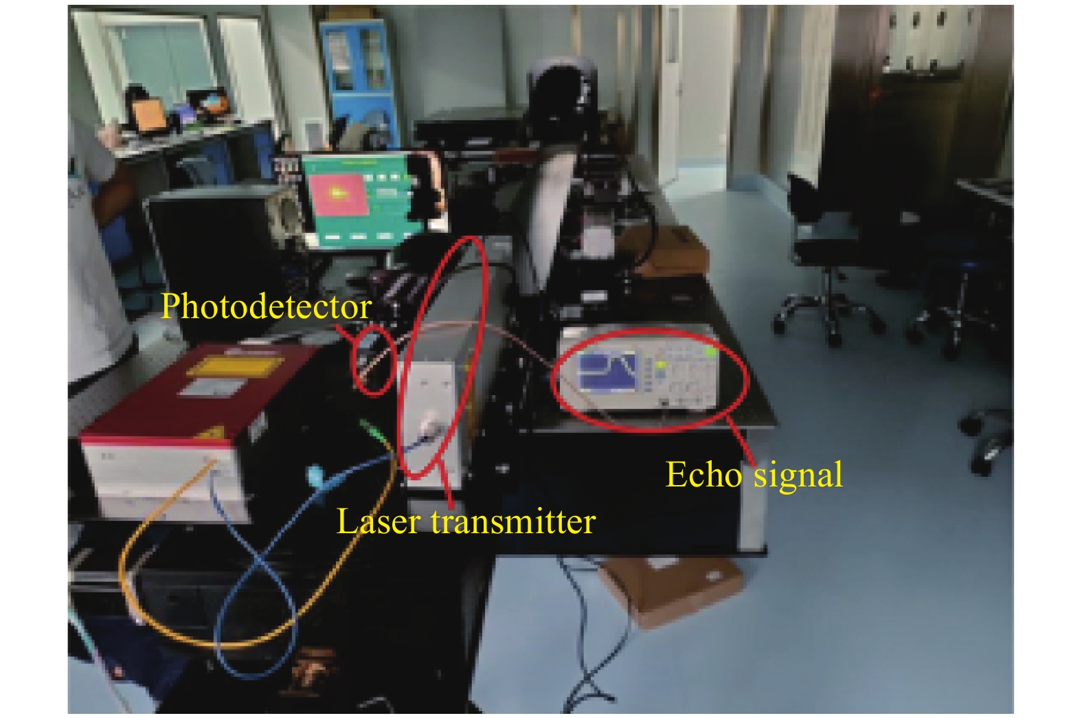
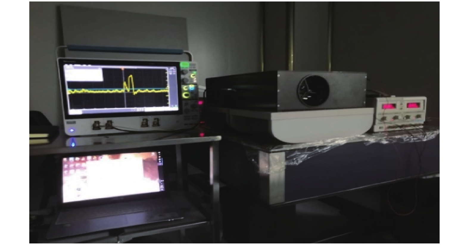
为了验证第2节中理论测试的正确性与真实性,笔者做出了以下两组实验:1064 nm和532 nm激光能量测试实验。实验的整体装置图见图10。
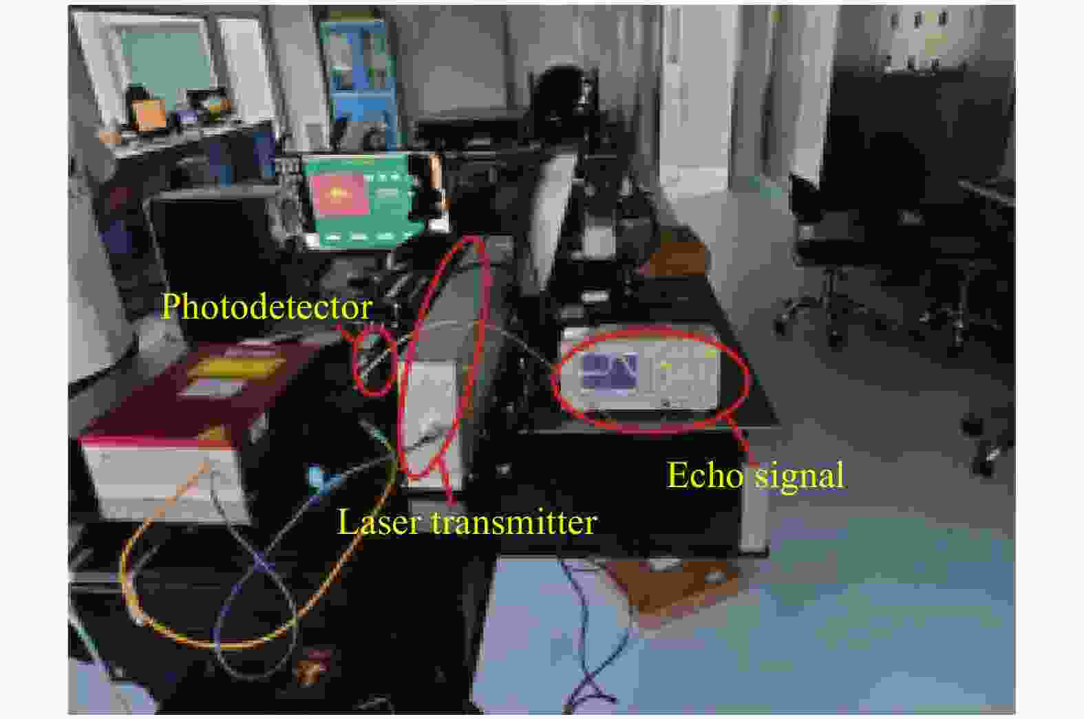
Figure 10. Overall configuration diagram of the experiment set
-
波长1 064 nm的激光能量测试需要经过以下四个步骤:
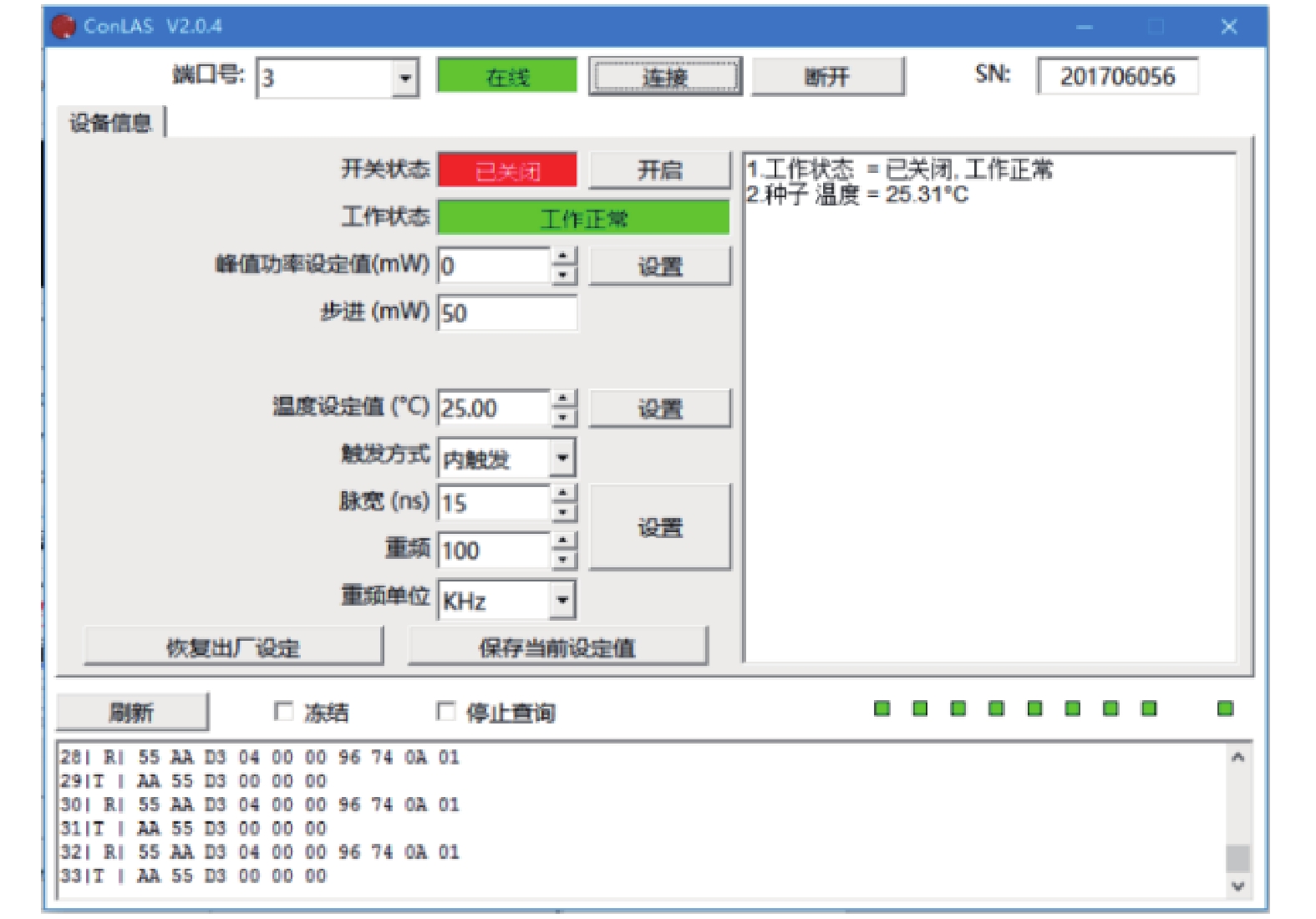
(1)测试1064 nm的激光器,将激光器连接RS232接口改变激光器串口至COM3,用线性直流电源调整激光器的电压至正常工作电压范围。激光器的上位机控制面板见图11。
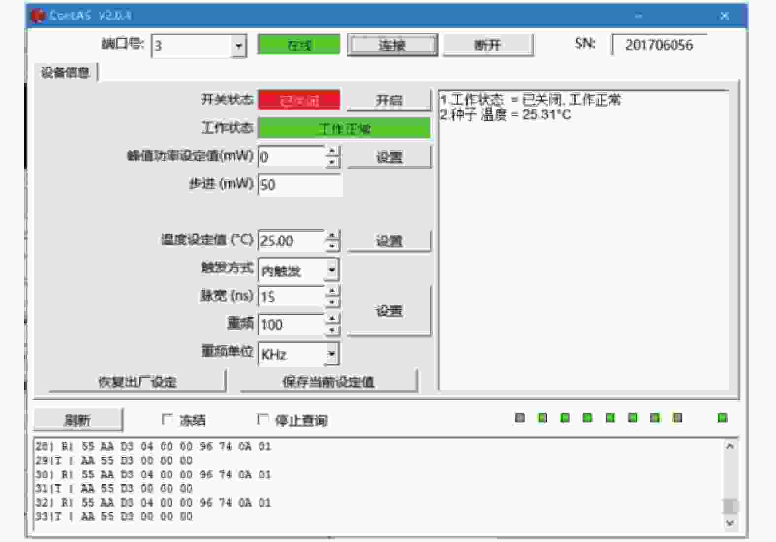
Figure 11. Upper computer control panel of the laser
(2)调制激光泵浦功率归零,将泵浦功率的步进值设为100 mW或者500 mW,逐步增加激光能量来保证探测器的安全。
(3)随后使用能量计测试激光功率,按着测试的数值选择能量计的合适量程再做测试,如果激光能量偏高,则采用能量衰减片来衰减激光能量。
(4)最后固定APD的接收窗口,让激光按照固定的角度打至光敏面,来观察示波器中的电压触发信号变化,并记录电压数值。
-
532 nm的激光器需要先对倍频器升温到147 ℃的温度下才能正常工作,上位机的操作和1 064 nm的无太大区别。因为PMT的灵敏度比APD高,它的阈值可达nW级,需要选用衰减能力更强的衰减片来保证模块的正常工作,其测试步骤如下:
(1)按着PMT的工作时序图设置好信号发生器,因为PMT需要门控功能来区分接收的光是由水面产生还是水底产生的,需要在信号发生器中设置好激光射到水面所需的时间,这个过程PMT处于关闭状态,接着激光到达水面后开启门控开关,来接收水底的回波信号。测试前,需要在ConLAS软件中将触发方式改为由信号发生器来控制的外部触发。
(2)将外界信号发生器的信号调至脉冲信号,选择占空比0.1%,高电平在3.5~5 V,低电平选0,周期为5 μs,脉宽为5 ns,上升时间为2 ns,下降时间为6 ns。
(3)选择探测器时需要查看是否有门控功能,以及门控功能是选用常开还是常闭等,按着对应的时序图设置信号发生器参数。一般使用这种外部信号触发功能的激光实验只可用于机载实验测试,而不适合船载测试,因为离水面距离太近,水面信号的门控时间无法精准控制。
(4)另外,要根据需要接收的激光波长波段选择合适的光电探测器,一般选择峰值灵敏度在最接近的波段作为探测光。
-
文中方法是在光电探测器的探测理论上测试激光能量值,但是实验测试值和真值总是存在一定的误差,为了减小这个误差,笔者做出如下几种分析。
(1)实验装置误差
测试装置的误差主要来源于仪器仪表的误差和电路的误差。所提方法采用了泰克公司采样率为2.5 G/s的示波器,如果回波信号的重复频率过快,有可能无法还原完整波形。另外,光电转换电路可能因为电源纹波的干扰以及电路的虚焊导致实验误差。
(2)环境误差
在不同的环境下测试会出现不同的实验结果,比如探测器的灵敏度受工作温度的影响,以及室内室外的自然光强度不同使得探测器产生的暗电流噪声不一样,探测器的响应度也会受到干扰。
(3)方法误差
由于人员的技术水平不够或者一些理论测试只能取近似值,导致最终结果产生误差。
前两种由硬件设施所致,可以选择同一实验环境,且在封闭黑暗环境下进行实验。而方法产生的误差,可以采取前人总结出来的经验公式对数据进行修正。如从实验3.1和3.2的测试结果中可以获得脉冲激光的时域波形,笔者根据传统经验公式对回波信号的脉宽进行误差分析[18]:
式中:t1为所测时域波形的脉宽;t2为波形记录的上升时间;t3为高速光电探测器的上升时间。
根据图10的测试结果,可得:
根据PMT模块(见图12)的测试结果,可得:
综上所述,接收到的回波信号与激光发射同步信号误差均在2%以内,证实回波信号的真实性。
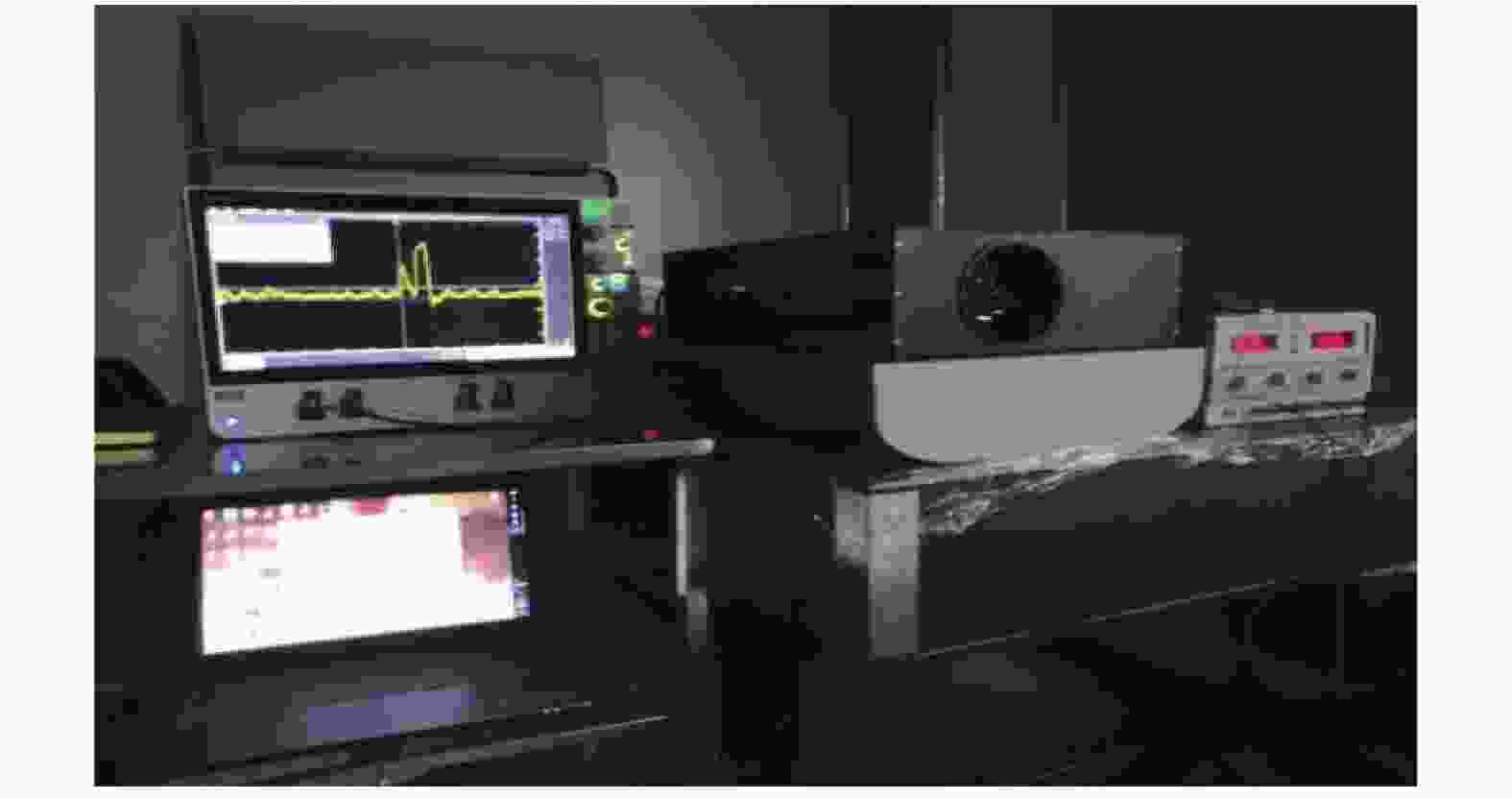
Figure 12. Laser test chart based on PMT module
-
文中设计并建立了一套基于APD和PMT探测器对波长1064 nm和532 nm的激光能量进行测试的方法。理论和实验结果表明:
它的关键技术在于使用1 GHz以上的高带宽低噪声的高速光电转换电路,有足够大的动态范围,可以还原整个原始波形,且在实验操作时只有激光泵浦功率这一个变量,操作极为简便。选用的探测器的响应度分别在532 nm和1064 nm均处于优值,在硬件层面上保证了实验的真实性,另外使用传统的能量计测试激光能量受限于能量计的量程,无法兼顾不同能量的激光信号,而文中采用的测试方法就显得更为灵活,不仅如此,如果需要测试其他波长的激光能量时,仅需要修改探测器和跨阻电路的芯片[19],选用靠近峰值响应度的探测器和与之带宽相当的跨阻芯片,就可以按照文中方法测试激光能量,足以体现该方法的先进性。同时,该方法可以在光电转换的理论方面继续优化,以达到更好的测量效果。
Testing method and experiment of large dynamic range energy of pulsed laser with wavelength of 1 064 nm and 532 nm
doi: 10.3788/IRLA20200417
- Received Date: 2021-04-08
- Rev Recd Date: 2021-06-04
- Publish Date: 2021-11-02
-
Key words:
- pulsed laser /
- APD and PMT detector /
- energy test
Abstract: The range of the energy meter is limited in laser energy measurement, and it cannot take into account the measurement of energy with a large dynamic range. In the photoelectric measurement, a laser energy measurement method based on APD and PMT photodetectors was proposed. The measurement of laser energy in the 1 064 nm and 532 nm bands was compelted through analyzing the detection performance of the photodetector and its interaction with subsequent processing circuits by this method. The voltage signal changes were observed by changing the pulse width, repetition frequency, and pump power of the adjustable laser light source. The size of the photocurrent was tested according to the magnification of the transimpedance amplifier circuit. The relationship between photodetector sensitivity and laser wavelength was used to find the corresponding detector sensitivity, photoelectric conversion gain and laser attenuation multiple. The laser energy value was tested, and the pulse width, repetition frequency and pump power value of the emitted laser were compared to ensure the calculation the authenticity of the method. The experiment proves that the proposed method can complete the laser energy test with a large dynamic range nJ-mJ, and the test error is less than nJ compared with the energy meter test.


 DownLoad: