


-
The outboard target indication equipment of modern supersonic fixed-wing aircraft is mainly used for the precision strike outside the defense area. The first generation equipment focuses on laser semi-active guidance irradiation and auxiliary reconnaissance. The second generation equipment increases the operating range, while adding laser semi-active guidance, image template matching guidance, geographic coordinates positioning/reconnaissance/search and rescue and other functions; The third generation equipment is generally used for distances of more than 70 km, with functions such as multi-sensor integration and information fusion, high-speed broadband data transmission, etc.
At present, the target indicating equipment in China is still in the second generation, and the dynamic performance of equipments are relatively low, which has been unable to meet the requirements of various types of aircraft with the increasing level of our army. The gap between the third-generation equipment commonly used in the United States and the equipment used in China is huge. Therefore, in order to narrow the gap between China and the international advanced technology, it is necessary to develop a new generation of airborne target indication technology with excellent performance and complete functions.
The key of airborne target indication technology is the high-precision stability control of LOS. The carrier disturbance to the servo speed loop directly affects the pointing of LOS, and reduce imaging quality of the system. Limited by the resonant frequency of equipment mechanical structure, the servo speed loop bandwidth is usually designed to be not higher than 50 Hz[1-3], it is difficult to achieve the design requirement of velocity stability less than 0.1°/s. In current engineering applications, the design of the speed loop of LOS stabilization system is mostly based on PID (proportional integral differentiation) control algorithm[4-5]. The disturbance rejection capability of the above design depends on closed-loop bandwidth of the control system[6], which is far from enough to isolate the aerial working disturbance. Some researchers has effectively improved the servo system performance by using optimal control method or adaptive control method in the simulation[7-9], but there are some problems in engineering applications such as difficulty of modeling and complex calculation. A high-order disturbance observer is the combination of a low-pass filter and the inverse model of the control object or a nominal model of the control object[10-11], the disturbance rejection capability of both types of disturbance observers were limited by high-order computing delay. In order to achieve advanced indicator technology of high precision control requirements, the disturbance estimation and compensation technology must be introduced on the basis of closed-loop control.
-
The experimental airborne target indication equipment with two axes and four frameworks is shown in Fig.1(a), each framework was driven by a large torque motor and a gyroscope sensed the angular rate. The outer frameworks shown in Fig.1(b) follow the inner frameworks, which isolate high-altitude wind-drag disturbance for inner frameworks. The inner frameworks shown in Fig.1(c) are the carriers of each photoelectric load, which determines the visual axis stability accuracy.
The transfer function of the inner pitch axis is:
The disturbance of a airborne target indication equipment mainly includes carrier disturbance, friction disturbance, wire disturbance and mass unequal moment disturbance, etc. Modeling these disturbances is a difficult task. It is possible to accurately observing the disturbance of the system by considering all kinds of disturbances as a "total disturbance", than taking the observation value as the control input of the system to compensate the disturbance, and therefore the disturbance can be isolated.

Figure 1. (a) Experimental equipment with two axes and four frameworks; (b) Mechanical drawing of the outer frameworks; (c) Mechanical drawing of the inner frameworks
-
Considering the transfer function of the experimental inner pitch axis, u is the input, y is the output, b is a constant, d(t) is the equivalent of the total disturbance in the system, a second-order system written in state space form is:
where
In Eq.(1), the state variable x cannot be measured, thus
$\hat x$ is observed by:The extended state observer for Eq.(1) is designed as:
Equation (3) can be divided into two parts: the first part is a Luenberger observer for the second-order plant in Eq.(1), and the second part is the estimated value of the total disturbance obtained by integrating the observation error with a gain of
${l_3}$ .Discretized by Zero-order holder, the Luenberger observer in Eq.(4) for the discrete domain is:
where
and
The gain matrices
${L_c}$ and${L_p}$ are obtained by using Taylor expansion of Eq.(5),$T$ is the discrete sampling time. The gain of the observer determines the observation bandwidth and affects the estimation performance of the observer. The relationship between the discrete domain elgenvalue$\beta $ and the continuous domain elgenvalue${\omega _0}$ was also shown in Eq.(5).With the ESO in Eq.(4),
$\hat d(t) = {{\textit{z}}_3}(t) = \displaystyle\int {{l_3}[y(t) - } $ $ {{{\textit{z}}_1}(t)]{\rm{d}}t}$ ,${\dot{ \hat d}}(t) = {\dot {\textit{z}}_3}(t) = {l_3}[y(t) - {{\textit{z}}_1}(t)]$ , the prediction of the total disturbance d(t) is determined based on the first-order Taylor series approximation shown in: -
The phase lag is usually caused by high order observer, can reduces the phase margin of the closed-loop system, which is undesirable in the observer-based control algorithms. A reduced-order extended state observer will less affects the phase margin of the system and therefore less affecting the stability of the closed-loop system.
If
$y$ and$\dot y$ can be measured in Eq.(1), the reduced order ESO can use state${{\textit{z}}_1}(t)$ following${x_2}(t) = \dot y(t)$ and${{\textit{z}}_2}(t)$ following${x_3}(t) = d(t)$ [12], thus, the ESO in Eq.(4) can be reduced to a second-order observer as:Similar to the ESO in Eq.(4), this RESO consists of a first-order Luenberger observer and an integrator. Discretization of the first-order Luenberger observer by using Zero-order holder:
where
With RESO in Eq.(7),
$\hat d(t + {l_d})$ is obtained as:The reduced-order ESO can reduce the phase lag in low frequency range and obtain better estimation performance. Its disadvantage is that the noise capacity in high frequency range decreases, but from the experimental data, the reduced-order ESO does not significantly amplify the high frequency noise.
-
The design scheme of the experimental servo system is shown in Fig.2. The servo system consists of control module, drive modules, motors, various sensors and digital observer, which receives instructions from a upper control computer.

Figure 2. Design scheme of the servo system
To verify the disturbance isolation ability of the designed ESO for the LOS stability control system, the bandwidth of the observer is designed at
${\omega _0} = $ 100 Hz, and the following two parts of experiments will be conducted: (1) Step response experiment; (2) Velocity stability experiment. The experimental equipment includes: a two-axis four-frameworks airborne target indication equipment, swing machine, one computer, a set of DSP emulators. -
Before we start the experimental analysis part, we need to find out the optimum closed-loop bandwidth frequency of the LOS we want. In practical engineering applications, the larger the bandwidth frequency is, the faster the response speed of the control system will be, but this will reduce the stability margin of the system and increase the interference of high-frequency noise. The bandwidth frequency of the electro-optical tracking stable platform servo controller should meet the following two requirements:
(1) The servo controller can effectively suppress the low-frequency disturbance of the photoelectric platform.
(2) The servo controller needs to have sufficient dynamic attenuation capability to the high frequency noise of the electronic system.
The low-frequency disturbance range of the photoelectric platform is usually at 0 Hz to 5 Hz. In order to effectively suppress the low frequency disturbance, the bandwidth of the servo system speed loop is designed to be about 5 times of the disturbance frequency range. The disturbance frequency range of an electronic system is usually at 50 Hz to 5000 Hz, the design of the LOS velocity loop bandwidth should be below 50 Hz to gain enough dynamic attenuation capability to the high frequency of electronic noise. Based on the above engineering application requirements, the visual axis speed loop bandwidth frequency should be designed above 25 Hz but below 50 Hz.
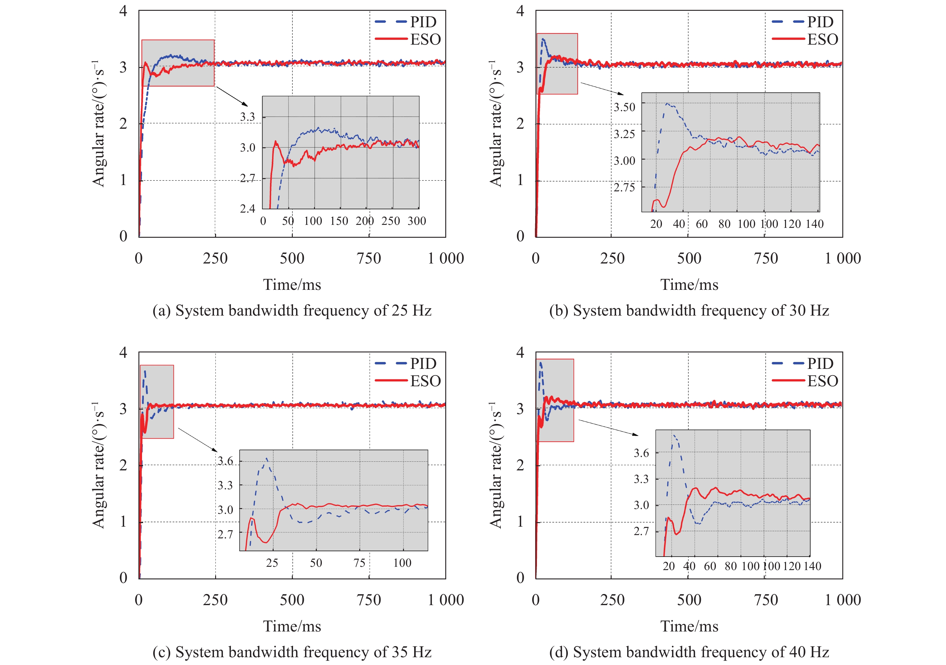
In this experiment, to compare the dynamic performance (stability time and overshoot) of the two control algorithms, the inner pitch axis was given a step input of 3 (°)/s, then observe the output curves of the two systems.
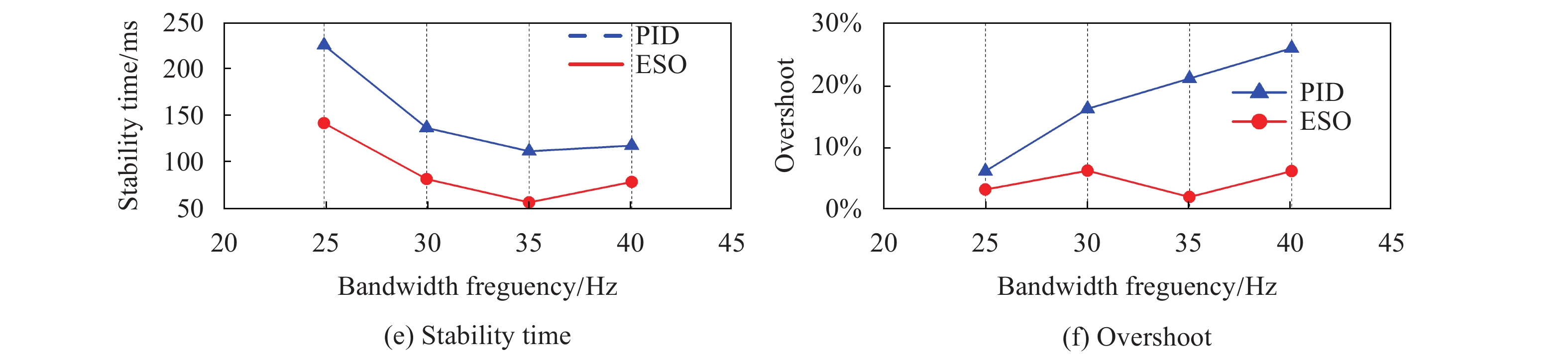
Figures.3(a)-(d) compared the system output curves with ESO based control algorithm and classical PID control algorithm under different bandwidth frequencies. It can be seen that ESO algorithm has shorter stability time and lower overshoot than PID algorithm under the system bandwidth frequency of 25 Hz, 30 Hz, 35 Hz and 40 Hz. The experimental data of stability time and overshoot were shown in Tab.1 and Tab.2 respectively. From Figs. 3(e)-(f), it can be concluded that the control system of the experimental inner pitch axis can achieve its best dynamic performance at the bandwidth frequency of 35 Hz, in which case, compared with PID algorithm, ESO algorithm show a better dynamic performance by reducing the stability time by 49.1% and overshoot by 88.4%.
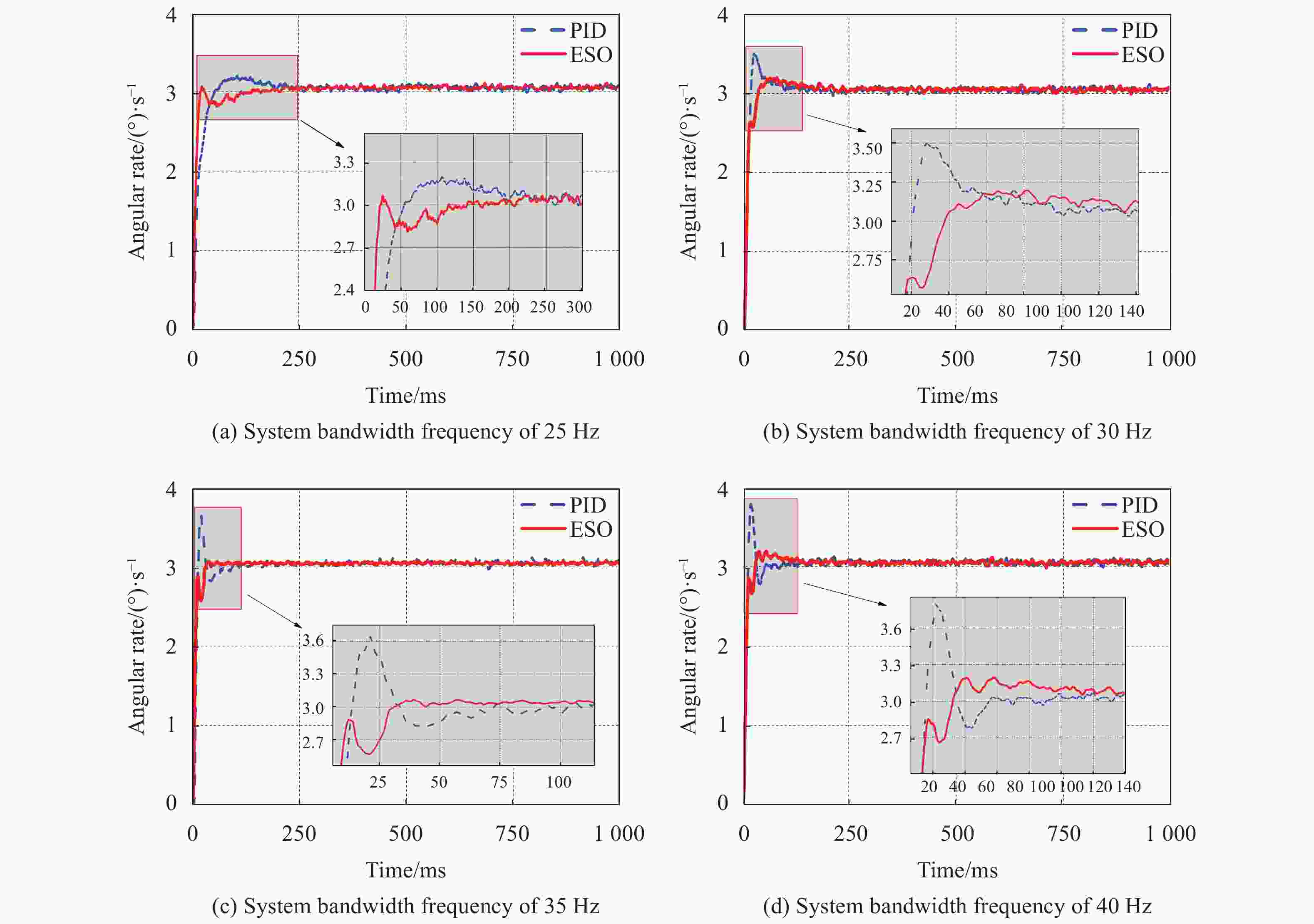
System bandwidth frequency/Hz Stability time of PID algorithm/ms Stability time of ESO algorithm/ms 25 226 142 30 137 82 35 112 57 40 118 79 Table 1. Stability time of the system at different bandwidth frequencies
System bandwidth frequency/Hz Overshoot of PID algorithm/(°)·s-1 Overshoot of ESO algorithm/(°)·s-1 25 0.145 0.057 30 0.447 0.149 35 0.594 0.069 40 0.739 0.146 Table 2. Overshoot of the system at different bandwidth frequencies
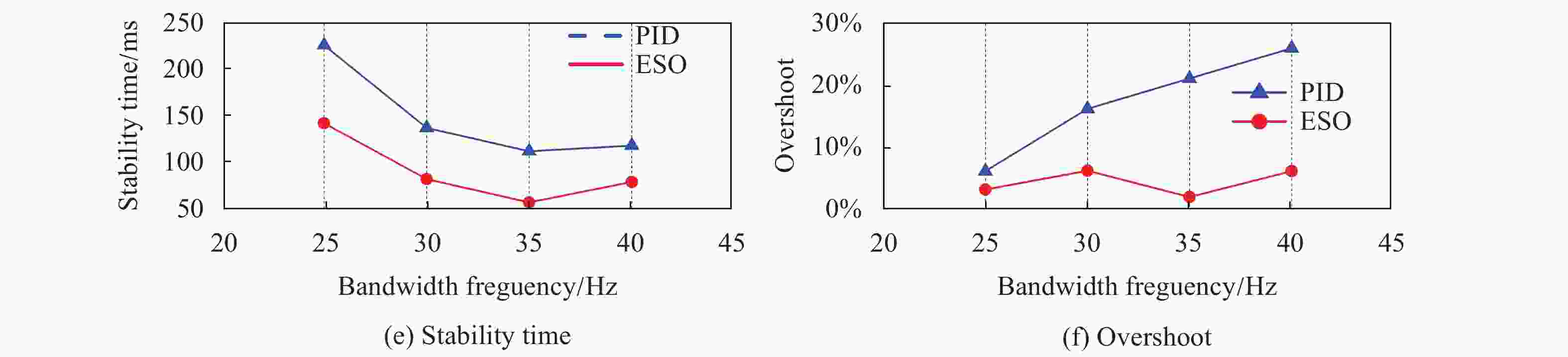
Figure 3. Step response output curve of the system at different bandwidth frequencies
The factors that affect the stability time and overshoot of the step response of the system include not only the closed-loop bandwidth of the system, but also the nonlinear time-varying disturbances such as friction torque disturbance, wire torque disturbance, etc. The disturbance observer can estimate the unknown disturbance such as friction torque disturbance and wire torque disturbance and feed forward compensation to the input, which can effectively reduce the overspeed and shorten the stability time, and improve the control quality and precision. The feed-forward compensation of disturbance estimation didn’t constitute a closed loop, so it did not affect the stability of the system. By comparing with the rising speed of the step response curves of the two control algorithms, the speed loop bandwidth of the disturbance feed-forward compensation algorithm is not significantly increased.
-
In this experiment, a target indication equipment was fixed on the swing table. The swing table was controlled to make sinusoidal motions at amplitude of 1° and the frequency from 1 Hz to 2.5 Hz (the maximum carrier disturbance frequency in practical application) to simulate the upper-air carrier disturbance, the inner pitch axis was controlled to work in steady state under the simulated disturbance. The maximum deviation of LOS was measured.
Figures. 4(a)-(d) compare the system output with ESO based control algorithm and classical PID control algorithm at different frepuencies of simulated disturbance. When the disturbance frequency is 1.0 Hz, 1.5 Hz, 2.0 Hz and 2.5 Hz, compared with PID algorithm, the disturbance residuals of ESO algorithm is reduced by 41.0%, 65.6%, 61.2% and 58.7% respectively. The disturbance residual data and curve was shown in Tab.3 and Fig.4(e) respectively. Based on the experimental results, it is concluded that ESO algorithm has a better disturbance rejection capability, so that the ESO algorithm based controller can achieve a better dynamic stability accuracy than the classical PID controller.

Figure 4. LOS velocity output curve of different frequencies of disturbance
Disturbance frequency/Hz Disturbance residuals of PID algorithm/(°)·s-1 Disturbance residuals of ESO algorithm/(°)·s-1 1.0 0.117 0.069 1.5 0.196 0.068 2.0 0.204 0.080 2.5 0.210 0.087 Table 3. Disturbance residuals of the system under different frequencies of disturbance
-
To achieve high precision indication and tracking of high dynamic targets, a control system design based on disturbance estimation and compensation techniques is proposed. A predictive extended state observer was designed to estimate the total disturbance and compensate to the controller in real time, the experiments of the designed control system were carried out in combination with the mathematical model of the experimental target indication equipment. The experimental results show that the designed control system can achieve the requirement that the speed stability is no more than 0.1 (°)/s under the carrier disturbance below 2.5 Hz. The designed controller improves the disturbance rejection capability of the system, in this way, a new method is provided to further improve the target indication accuracy of advanced airborne equipment.
Airborne target indication stability control based on improved extended state observation
doi: 10.3788/IRLA20200442
- Received Date: 2020-11-11
- Rev Recd Date: 2021-01-29
- Available Online: 2021-05-12
- Publish Date: 2021-03-15
-
Key words:
- target indication /
- improved extended state observer /
- disturbance residuals /
- velocity stability
Abstract: A control algorithm based on disturbance estimation and compensation theory was proposed in order to meet the design requirement of apparent axis velocity stationary-error in advanced airborne target indication equipment. An improved extended state observer (ESO) was designed to reduce the phase delay of the high order observer and to improve the control accuracy of the line of sight (LOS). The step response and velocity stability capability of the improved control algorithm were tested in the experiment, and were compared with the classical control algorithm. By analyzing the step experiment results, it can be seen that the designed control algorithm can achieve shorter stability time and lower overshoot under different closed-loop control bandwidth. Under the closed-loop bandwidth of 35 Hz, the stability time of PID algorithm was reduced by 49.1% and the overshoot was reduced by 88.4%, and the dynamic performance of the system was significantly improved. The velocity stability experimental results show that the designed control algorithm can significantly improve the rejection capability of different disturbances of amplitude of 1° and frequency within 2.5 Hz, the velocity error of the LOS was controlled within 0.1(°)/s, and the disturbance residuals were less than 0.1(°)/s. The designed control algorithm meets the design requirements of advanced target indication equipment and has high practical value for improving the dynamic performance of the system and the velocity stability of the LOS.


 DownLoad: