


-
快速控制反射镜(Fast Steering Mirror, FSM)是一种可以在光源和接收器之间控制光束方向的反射镜装置,具有体积小、功耗低、响应速度快,精度高等特点,最早应用于自适应光学系统中,现广泛应用在精密捕获、瞄准和跟踪、光束稳定、目标指向、空间激光通信等领域[1]。其中,FSM系统的控制带宽表征了系统对输入信号的跟踪能力,系统控制带宽越高,系统响应速度越快,反应时间越短,FSM系统的跟踪能力就越精确、及时[1]。而国内现有的大口径快反镜系统控制带宽普遍有待提高,所以大口径、高控制带宽的FSM系统是未来FSM系统研究的重点领域。提高系统控制带宽需要提高系统的高阶固有频率,减小系统低阶固有频率[1],而系统的固有频率与系统在该振型方向上的刚度有关,故有必要对系统的工作刚度和固有频率计算公式展开研究。
国内外已有多名学者对快反镜系统工作刚度和固有频率计算公式开展过分析研究。付锦江等[1]对二自由度椭圆弧柔性支撑系统的前四阶振型、运动刚度和固有频率进行了分析,并通过反复计算得到了椭圆弧柔性支撑系统的优化设计结果;艾志伟等[2]对FSM系统进行建模分析,并讨论了系统机械结构与控制系统的关系;徐宁等[3]对快反镜系统固有频率计算公式进行了推导,并进行了有限元仿真测试。上述工作主要集中于对快反镜系统刚度组成以及固有频率的分析,并以固有频率计算公式得出各方向上的刚度设计范围,缺乏以提高系统控制带宽为目标的定量优化计算。故有必要利用优化算法对快反镜系统结构固有频率进行定量的多目标优化计算。
对于单个柔性铰链的工作刚度以及其多目标优化计算,也有多位学者对其进行了研究。吴松航等[4]利用NSGA-II算法对单个椭圆的柔性铰链进行了减小z轴扭转刚度,提高x,y轴扭转刚度的多目标优化计算;卢倩等[5]对单个深切口柔性铰链的刚度矩阵进行了推导,并进行了减小两个工作方向刚度、提高七个非工作方向刚度的多目标优化计算,优化率在10%~68%;以上工作对于单个柔性铰链的分析优化有很大的指导意义,但缺乏将柔性铰链代入整个系统进行优化分析。
针对以上问题,文中对二自由度快反镜系统的固有频率计算进行了理论分析,并基于减小系统低阶固有频率,提高系统高阶固有频率提出了一种多目标优化函数。首先,文中对深切口柔性铰链组成的二自由度快反镜系统进行了有限元仿真分析,得出了前四阶固有频率的振型,并将其简化为弹簧的串并联模型,针对传统刚度分析不适用于第三阶振型运动方向的问题,对其振型方向刚度与单个柔性铰链刚度之间的关系进行了分析,得出了新的快反镜第三阶振型方向的刚度理论公式;然后,文中利用能量法以及卡式第二定理对深切口柔性铰链工作刚度进行了推导,并利用非线性拟合对其进行了简化,解决了传统深切口柔性铰链工作刚度计算公式过于复杂的问题;之后,文中结合以上的刚度计算公式,对快反镜固有频率计算公式进行了有限元仿真验证,证明了三阶固有频率计算公式的准确性。最后,文中提出了一种减小系统低阶固有频率,提高系统高阶固有频率的多目标优化函数,并对四个不同的目标赋予不同的权值,利用遗传算法对其进行优化计算,并进行了有限元仿真验证,结果证明,优化计算有效地减小了系统低阶固有频率,提高了系统高阶固有频率,设计结果良好,理论计算与仿真结果吻合良好。文中提出的基于系统固有频率的多目标优化函数以及推导简化的深切口柔性铰链工作刚度计算公式对于进一步提高快反镜系统控制带宽、优化快反镜结构设计具有一定意义。
-
文中讨论的快速控制反射镜以及柔性支撑系统三维结构模型如图1所示。

Figure 1. (a) Overall structure of fast steering mirror; (b) Flexible support system structure
图1(a)中柔性支撑结构与隔离板之间采用螺栓连接;隔离板与反射镜之间采用胶粘连接。图1(b)中的坐标系为O-xyz,O为柔性支撑系统转动中心,工作方向为绕x,y轴的转动。该结构由四个结构完全一样的柔性铰链组成,其中铰链1、3组合,可以实现结构在x轴上的偏转;铰链2、4组合,可以实现结构在y轴上的偏转[1]。单个深切口柔性铰链模型如图2所示。

Figure 2. (a) Plan view of deep-cut flexure hinge; (b) Schematic diagram of deep-cut flexure hinge
图2 中的坐标系为
${{{O}}'} - {x'}{y'}{{\textit{z}}'}$ ,该坐标系适用于单个深切口柔性铰链。图中,h为柔性铰链的高度,w为柔性铰链的宽度,t为柔性铰链最小切割厚度。同时椭圆切口的长半轴和短半轴分别为a、b。对FSM系统进行模态分析,结果如图3所示。

Figure 3. (a) First-order mode; (b) Second-order mode; (c) Third-order mode; (d) Fourth-order mode
如图3可知,FSM系统前四阶模态振型为绕x,y轴偏转,绕z轴扭转以及沿z轴的拉压。所以可以将二自由度柔性支撑系统简化为弹簧串并联模型,并进行振型方向上的刚度计算[1]。
(1)第一阶振型:绕x轴转动
绕x轴的转动刚度是由铰链1、3的刚度
${K_{{\theta _{{z'}}},{M_{{z'}}}}}$ 并联,铰链 2,4的刚度${K_{{\theta _{{y'}}},{M_{{y'}}}}}$ 并联,再由二者串联而成[1],简化模型如图4(a)所示,计算公式如下:
Figure 4. (a) Simplified diagram of first-order mode shape stiffness; (b) Simplified diagram of second-order mode shape stiffness; (c) Simplified diagram of third-order mode shape stiffness;(d) Simplified diagram of fourth-order mode shape stiffness
计算结果为:
(2)第二阶振型:绕y轴转动
绕y轴的转动刚度是由铰链2、4的刚度
${K_{{\theta _{{{\textit{z}}'}}},{M_{{{\textit{z}}'}}}}}$ 并联,铰链 1、3的刚度${K_{{\theta _{{y'}}},{M_{{y'}}}}}$ 并联,再由二者串联而成[1],简化模型如图4(b)所示,计算公式如下:计算结果为:
(3)第三阶振型:绕z轴扭转
常用的二自由度快反镜系统三阶振型计算公式为:
在柔性支撑系统面对绕z轴的转矩
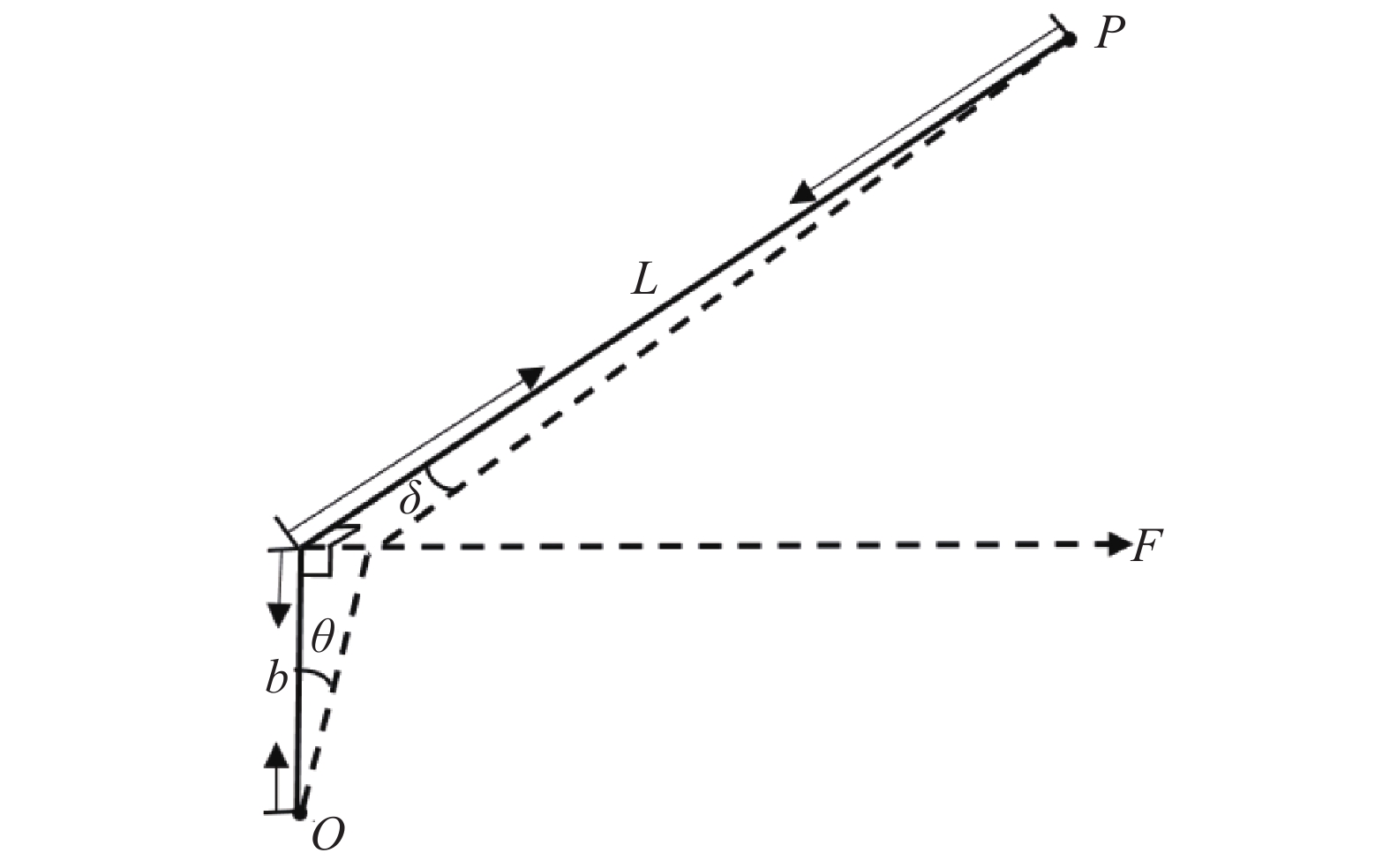
${M_{\textit{z}}}$ 时,${M_{\textit{z}}}$ 分布在四个铰链上的剪切力为$F = \dfrac{{{M_{\textit{z}}}}}{L}$ ,其中,$L$ 为柔性铰链偏转中心到柔性支撑系统偏转中心的距离,即系统偏转半径。但是分析快反镜系统第三阶运动形式可知,${K_{{\theta _{\textit{z}}},{F_y}}}$ 只能表述柔性铰链在受切向力的情况下绕y轴偏转的角度,而与快反镜系统绕z轴的偏转不在一个平面上。其简化模型如图5所示。
Figure 5. Simplified model of third-order modal stiffness
图5中,O点为柔性铰链偏转中心,b为柔性铰链短半轴长度,L为柔性铰链至支撑系统转动中心的长度,P为支撑系统转动中心,F为柔性铰链所受切向力。传统公式中的
${K_{{\theta _z},{F_y}}}$ 只能表示在受到切向力时产生的偏转角$\theta $ ,而系统三阶振型产生的扭转角为$\delta $ ,故传统公式的$4L{K_{{\theta _z},{F_y}}}$ 无法表示系统扭转刚度。根据图5中的几何关系可以得出:
因为是小变形情况,有:
故:
式中:
${K_{{\delta _z},{F_{{y'}}}}}$ 表示在单位切向力F的 作用下,单个柔性铰链围绕支撑系统偏转中心产生的偏转角。所以,绕z轴扭转刚度是由四个铰链的刚度${K_{{\delta _z},{F_{{y'}}}}}$ 并联组合而成,简化模型如图4(c)所示,故其计算公式为:计算结果为:
(4)第四阶:沿z轴拉压刚度
沿z轴的转动刚度是由铰链2、4的刚度
${K_{{\delta _{{x'}}},{F_{{x'}}}}}$ 并联,铰链 1、3的${K_{{\delta _{{x'}}},{F_{{x'}}}}}$ 并联,再由二者串联而成[1],简化模型如图4(d)所示,计算公式如下:计算结果为:
-
定义柔性铰链上的力和弯矩为
$F = [ {{F_{{x'}}}} {F_{{y'}}}{F_{{{\textit{z}}'}}} $ $ {M_{{x'}}}{M_{{y'}}}{ {{M_{{{\textit{z}}'}}}} ]^{\rm T}}$ ,对应的铰链变形为$D = {\left[ {{\delta _{{x'}}}{\rm{ }}{\delta _{{y'}}}{\rm{ }}{\delta _{{{\textit{z}}'}}}{\theta _{{x'}}}{\theta _{{y'}}}{\theta _{{{\textit{z}}'}}}} \right]^{\rm T}}$ ,根据材料力学理论可得它们的关系为[1]:其中,C为柔性铰链的柔度矩阵,公式为:
根据参考文献[6],柔性铰链工作方向上的弯曲应变能公式为:
式中:E为柔性铰链材料的杨氏模量;
$I({x'})$ 为柔性铰链截面对中心轴的惯性矩;${F_{{x'}}}$ 为铰链自由端上沿${x'}$ 轴向的拉力;${M_{{{\textit{z}}'}}}$ 为铰链自由端上沿${y'}$ 轴切向力引起的转矩以及绕${{\textit{z}}'}$ 轴的转矩之和。先对旋转力矩${M_{{{\textit{z}}'}1}}$ 引起的绕${{\textit{z}}'}$ 轴的转矩进行分析,根据卡式第二定理可得,柔性铰链的转角计算公式为[7]:根据图2(b)可得:
将公式(19)代入公式(15)可得柔性铰链应变能为:
再将公式(21)代入公式(17)可得转角
${\theta _{{z'}1}}$ 为:将公式(19)、(20)和公式(22)代入公式(14)中,可计算出柔性铰链工作方向上的柔度为:
设
$p = \dfrac{a}{t}$ ,则设
$ Y={\displaystyle {\int }_{-\frac{\pi }{2}}^{\frac{\pi }{2}}\frac{\mathrm{cos}\varphi }{{(2p+1-2p\cdot \cos\varphi )}^{3}}{\rm{d}}\varphi }$ ,因为Y求积分结果过于复杂,不利于工程上的优化设计应用,所以采用非线性曲线拟合的方法,对Y进行化简。曲线拟合的优度判断采用残差平方和(SSE)、判定系数(R-Square)、调整的判定系数(Adjusted R-Square)、均方根误差(RMSE)和残差分布图进行判定,残差平方和、均方根误差越接近0,判定系数、调整的判定系数越接近1,则曲线拟合程度越好[8]。对Y函数采用了幂函数拟合,如图6所示,由残差分布图以及各项判定系数可知,幂函数拟合结果较好,满足误差要求。

Figure 6. (a) Non-linear fitting curve diagram; (b) Non-linear fitting determination coefficient
拟合结果为:
则深切口柔性铰链工作方向上的柔度为:
根据参考文献[5],计算系统前四阶固有频率所需的深切口柔性铰链在其他次要方向上的柔度理论计算公式如下:
-
根据模态分析结果可知,FSM系统前两阶固有频率振型分别为绕x,y两轴的扭振运动,故可将其简化为单自由度扭振模型,根据参考文献[1,9-10]可知,该模型在扭振方向上的运动刚度和该方向上固有频率的关系可表示为:
式中:
${K_{\theta n}}$ 为运动方向的扭转刚度;${J_n}$ 为运动方向的转动惯量。快反镜系统第三阶振型绕z轴扭转,因为是小变形运动,故可将其简化为单自由度的扭转振动,将新推导出的三阶振型方向上的刚度计算公式代入计算,则三阶固有频率计算公式为:
式中:
${K_{{\theta _z}}}$ 为系统绕z轴的扭转刚度;${J_z}$ 为运动部分绕z轴扭转刚度。快反镜系统第四阶为沿z轴拉压,根据参考文献[8]可知,第四阶固有频率计算公式为:
式中:
${K_{{\delta _z}}}$ 为系统沿z轴的拉压刚度;$M$ 为运动部分质量。 -
利用ug软件对深切口柔性铰链进行建模,并导入Ansys软件进行了有限元仿真验证,如图7所示。
仿真结果对比如表1所示。文中推导出的深切口理论计算公式计算结果与有限元仿真结果误差不超过9%,证明了理论推导结果的准确性。

Figure 7. Finite element verification of the working stiffness of the deep-cut flexure hinge
a
/mmb
/mmt
/mmw
/mmTheoretical
calculation results
/N·m·rad−1Finite element
simulation results
/N·m·rad−1Error
percentage10 8 1 8 25.3799 26.0417 −2.54% 10 6 1 8 33.8399 32.6513 3.64 % 5 3 0.5 8 8.4600 8.2527 2.45% 5 3 0.5 5 5.2875 5.1466 2.74% 5 2 0.5 5 7.9312 7.2922 8.76% Table 1. Comparison of theoretical calculation and finite element simulation of working stiffness of deep-cut flexure hinge
-
利用ug软件对快反镜系统进行建模,并导入Ansys软件进行了模态分析,如图8所示。

Figure 8. Third-order mode shape simulation diagram
有限元仿真验证结果如表2所示。根据有限元仿真结果可知,该理论公式与有限元仿真结果误差不超过1.7%,证明了三阶振型计算公式以及新推导系统绕z轴扭转刚度计算公式的准确性。
a
/mmb
/mmw
/mmt
/mmMirror
thickness: h
/mmTheoretical
calculation
value of
third-order
mode/HzThree-order
mode finite
element simulation
value/HzError
percentage4 3.5 5 0.8 23 284.40 286.25 0.61% 10 8 8 1 15 218.90 220.17 −0.58% 6 5 8 1 15 434.29 427.11 1.68% Table 2. Comparison of theoretical calculation and finite element simulation of three-boundary natural frequency of fast mirror system
-
文中要求设计的快反镜系统镜面直径D为100 mm,反射镜厚度h为15 mm,隔离板厚度为3 mm。反射镜系统偏转范围为
$ \pm {\rm{3\;mrad}}$ ,重复定位精度${\delta _p} \leqslant 8\;{\rm{urad}}$ 。柔性支持系统材料为TC4,隔离板材料为铟钢,反射镜材料为微晶玻璃。初始结构参数如表3所示。a/mm b/mm t/mm w/mm L/mm D/mm h/mm 10 8 1 8 25 100 15 Table 3. Initial structure parameters of the fast steering mirror system
图3中,参数a,b,t为自变量,参与函数优化设计;w,L,D,h为定值,不参与优化设计。
-
在快速控制反射镜的系统设计中,为提高系统控制带宽,要求系统结构的固有频率高于系统的控制带宽的2~4倍。但是这样的设计会导致固有频率过大,在FSM系统转动惯量不变的情况下,系统工作方向上的刚度就会过大,这会极大地增大系统驱动器的负担[1]。故所采用的设计方法是尽可能地减小系统工作方向上的低阶固有频率,并通过控制系统对其加以抑制,而另一方面提高系统非工作方向上的高阶固有频率,并且越大越好,以提高系统的控制带宽[2]。
根据公式(30)~(32)可知,系统的四阶固有频率大小
${f_n}$ 与柔性支撑系统三轴转动刚度的平方根$\sqrt {{K_{\theta n}}} $ 和z轴拉伸刚度的平方根$\sqrt {{K_{{\Delta _n}}}} $ 成正比关系,因为其比值随系统负载的质量和转动惯量不同而变化。为适应不同负载的快反镜系统,故将转动惯量和质量值简化为各阶固有频率前的加权系数,构建如下多目标优化函数:式中:
${\;\beta _1} \sim {\;\beta _4}$ 为柔性支撑系统各运动方向刚度平方根的加权系数,反映了各运动方向刚度平方根在固有频率优化中的重要性。在多目标优化问题中,采用不同的加权值会产生不同的优化结果,故一般会产生最优解集,需根据各子目标的重要程度不同以及多次的参数调整来最终确认加权值,从而最终计算出一组最优解[4]。
文中采用固定权重值法来解决该多目标优化问题。在固有频率的优化计算中,振型为绕y轴扭转的二阶固有频率决定了低阶工作方向固有频率的上限,振型为沿z轴扭转的三阶固有频率决定了高阶非工作方向固有频率的下限。根据FSM系统设计提高非工作方向上的固有频率,同时减小工作方向上的固有频率这一设计思想,着重在降低二阶固有频率的同时提高三阶固有频率是该优化计算中比较重要的部分,故
$\sqrt {{K_{\theta_y}}} $ 和$\sqrt {{K_{\theta_\text{z}}}} $ 两个子目标在优化函数中占据比较重要的地位,在分配权重时需要予以更大的权重值。根据以上需求,并通过调参计算,选取的加权系数为:β1= 0.2,β2= 0.3,β3=0.4,β4=0.1。 -
(1)柔性铰链强度不等式约束
柔性铰链弯曲时,铰链的最大应力出现在铰链的最小切割厚度t处,同时有应力集中的影响,故根据材料力学中的纯弯曲理论,柔性铰链弯曲时最大应力为[8]:
式中:
${K_t}$ 为应力集中系数[8];${M_{\max }}$ 为铰链在最大偏转角时外部施加的转矩。其计算公式为:将公式(35)代入公式(34)可得:
TC4屈服强度为
$4.3 \times {10^8}$ Pa,安全系数为1.5,将屈服强度和安全系数代入公式(36)可得:(2)柔性铰链运动精度不等式约束
在对柔性铰链运动精度的分析中,一般将柔性铰链几何中心点的位移,即柔性铰链偏转中心的位移作为衡量柔性铰链运动精度的定量指标[8],根据材料力学的公式可得:
其中,
$\left\{ \begin{array}{l} I({{{x}}'}) = \dfrac{{{{w}}{{{t}}^{\rm{3}}}{\rm{(}}{{{x}}'}{\rm{)}}}}{{{\rm{12}}}} \\ \;\;\;\;\;\;\;\;\;\;\;\;\;\;\;\;\;\;\;\;\;\;\;\;\;\;\;\;\;{\text{。}}\\ M({{{x}}'}) = M \\ \end{array} \right.$ 将公式(38)化为极坐标形式可得:
将公式(19)代入公式(39),并代入柔性铰链重复定位精度
${\delta _p} \leqslant 8 $ μrad,可得出柔性铰链运动精度约束表达式为: -
优化模型为:
将柔性铰链的长轴a、短轴b和最小切割厚度t作为变量。同时根据几何约束条件可得出线性不等式约束矩阵A为:[0 −1 5 0; −1 0 5 0; 1 0 −50 0; −1 1.2 0 0],b=[0; 0]。根据现有的加工精度,得出边界约束lb=[0,0,0.8],ub=[20; 20; 5]。非线性不等式约束为柔性铰链强度不等式约束c1,柔性铰链运动精度不等式约束c2。
-
遗传算法(Genetic Algorithm,GA)最早是由美国的 John holland于20世纪70年代提出的,该算法的设计灵感来自于大自然中生物体进化的原理,将达尔文生物进化论的自然选择和遗传学机理的生物进化过程的计算模型作为搜索最优解的方法[11]。该算法通过数学的方式,将问题的求解过程转换成类似生物进化中的染色体基因的交叉、变异等过程[11]。与一般的优化算法相比,遗传算法从问题解的串集开始搜索,而不是从单个解开始。传统优化算法是从单个初始值迭代求最优解的,容易误入局部最优解。而遗传算法从串集开始搜索,覆盖面大,利于全局择优,不易陷入局部最优解[12]。在求解较为复杂的组合优化问题时,相对一些常规的优化算法,通常能够较快地获得较好的优化结果,遗传算法的基本运算过程如图9所示[13]。
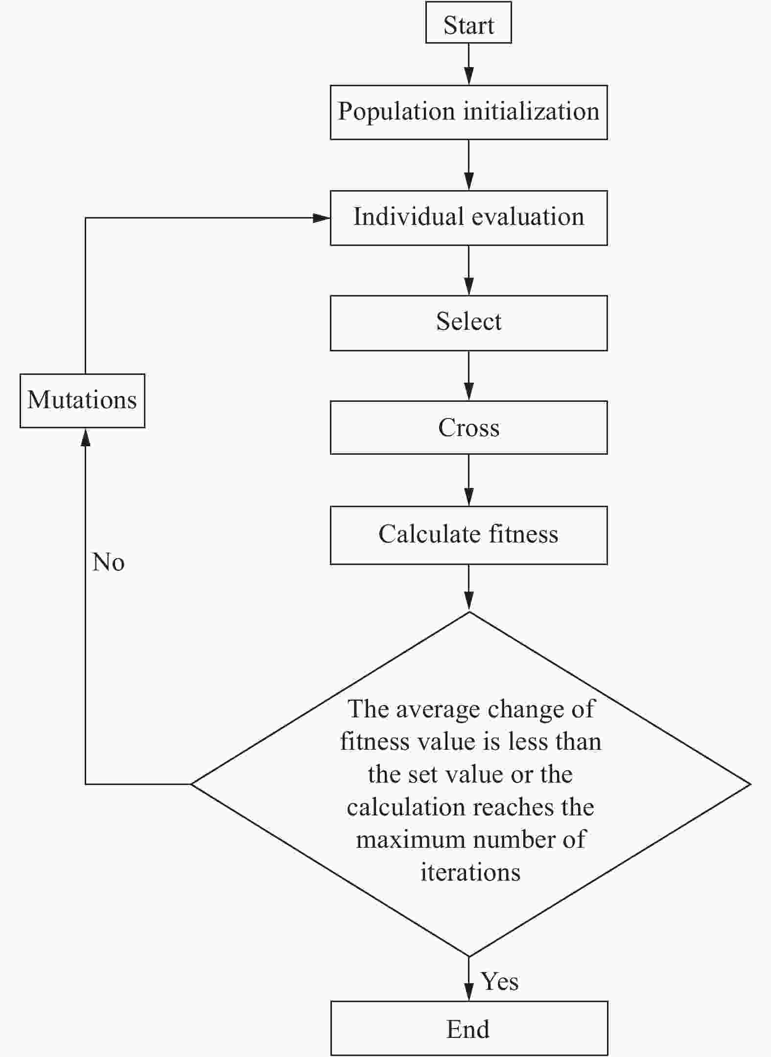
Figure 9. Optimization flow chart of genetic algorithm
-
文中采用matlab遗传算法工具箱进行优化计算,优化初始值为a=10,b=8,t=1。设定的优化迭代次数上限为100代,终止计算条件为两次迭代的适应度函数度值的平均变化小于1×10⁻⁶并且不违反约束。优化计算结果为a=4.798,b=3.999,t=0.8。为便于加工,对以上优化结果进行近似处理,所得的最终优化结果参数如表4所示。
Parameter Value a/mm 4.8 b/mm 4 t/mm 0.8 G(x) 0.0181 Table 4. Optimization results of genetic algorithm
利用以上优化后的结构参数,并结合之前所展示的系统结构其他关键部件参数,对该结构进行了ug 建模,优化结构三视图如图10所示。

Figure 10. (a) Front view; (b) Right view; (c) Bottom view
利用之前推导的刚度计算公式计算该优化结构四个振型方向上的刚度,并与初始结构的四个振型方向刚度做对比,以初步分析优化计算的效果,对比结果如表5所示。
a/mm b/mm t/mm K1/N·m·rad−1 K2/N·m·rad−1 K3/N·m·rad−1 K4/N·m−1 G(x) Initial value 10 8 1 50.04 50.04 844.6296 1.323e+06 0.0279 Optimized value 4.8 4 0.8 40.51 40.51 3.3602e+03 2.343e+06 0.0181 Optimization rate −19.04% −19.04% 297.83% 77.09% 41.58% Table 5. Comparison of system stiffness between multi-objective optimized structure and initial structure
从以上计算结果可以看出,优化后的快反镜结构工作方向刚度减19.04%,非工作方向刚度提高了297.83%和77.09%,优化函数值下降41.58%。因为系统固有频率与系统刚度成正相关,与系统负载成负相关,故在反射镜负载不变的情况下,前二阶固有频率会下降,而三、四阶固有频率会上升,低级固有频率与高阶固有频率的差距会进一步提高,故该优化结构初步符合设计预期。
为进一步分析优化结构的固有频率,并得到更加直观的结果,文中将优化后的结构进行Ansys模态仿真,结果如图11所示,仿真结果以及与初始结构对比如表6所示,从以上仿真结果可以看出,经过优化计算,快反镜一、二阶固有频率较初始结构分别下降8.08%和5.40%,分别为55.8 Hz和57.5 Hz。三、四阶固有频率较初始结构上升112.59%和16.80%,达到503.7 Hz和642.4 Hz,可见优化计算达到其设计目的,满足快反镜系统的设计要求。其中最为关键的二、三阶固有频率得到了较大的优化,证明了加权系数的有效性。该优化计算有效降低了结构工作方向上的低阶固有频率,为下一步加入控制系统打下了良好的基础,使系统的低阶固有频率可以得到有效抑制。同时,该优化计算大大提高了结构非工作方向上的三、四阶固有频率,使系统系统控制带宽可以得到显著提高,预计在加入控制系统抑制低阶频率后系统控制带宽可达300 Hz左右。

Figure 11. (a) First-order mode; (b) Second-order mode; (c) Third-order mode; (d) Fourth-order mode
First-order mode/Hz Second-order mode/Hz Third-order mode/Hz Fourth-order mode/Hz Initial structure 60.715 60.814 236.93 549.97 Optimized structure 55.807 57.533 503.68 642.38 Optimization rate −8.08% −5.40% 112.59% 16.80% Table 6. Comparison of the fourth-order natural frequency between the optimized structure and the initial structure
-
为对二自由度深切口柔性铰链快速控制反射镜系统进行控制带宽优化设计,文中首先对快速控制反射镜系统四阶固有频率进行了有限元仿真分析,并对四个振型方向上工作刚度进行了理论分析推导,解决了传统计算公式不适用于三阶振型方向的问题;然后利用能量法和卡式第二定理,对深切口柔性铰链的工作刚度计算公式进行推导,并利用非线性拟合方法对计算公式进行了拟合简化,得出的简化计算公式与有限元仿真结果误差不超过9%,解决了传统公式过于复杂的问题;接着利用以上推导出的刚度公式进行了快反镜系统第三阶固有频率理论计算和有限元仿真验证,计算结果与仿真结果误差不超过1.7%,证明了新推导的系统三阶振型方向刚度和三阶固有频率计算公式的可靠性;最后以系统一、二阶固有频率的平方根最小,三、四阶固有频率的平方根最大为目标进行了多目标优化设计,得出的最优化结构有效降低了一、二阶固有频率,提高了三、四阶固有频率,并进行了有限元验证,证明了优化结果的可靠性和有效性。文中所推导的公式和提出的优化方法对二自由度柔性铰链快反镜系统的固有频率理论分析和提高控制带宽有一定的工程意义。
Optimal design of natural frequency of two-degree-of-freedom fast steering mirror system
doi: 10.3788/IRLA20200450
- Received Date: 2020-11-16
- Rev Recd Date: 2021-03-03
- Publish Date: 2021-06-30
-
Key words:
- fast steering mirror /
- control bandwidth /
- optimal design /
- natural frequency /
- the stiffness of flexure hinge
Abstract: In the design of a two-degree-of-freedom fast steering mirror system, in order to increase the control bandwidth of the system, the low-order natural frequency in the working direction should be reduced as much as possible, and the high-order natural frequency in the non-working direction should be increased. This subject used a deep-cut flexure hinge fast-reflection mirror system as the research object. First, the vibration mode movement direction of the first four-order natural frequency of the system was analyzed, and considering that the traditional stiffness calculation method was not suitable for the third-order mode direction problem, the stiffness calculation formula in the third-order mode shape direction was re-derived; secondly, the working stiffness of the deep-cut flexure hinge was deduced by the energy method and the second card theorem, and the nonlinear fitting was simplified. The error between the simplified calculation formula calculation result and the finite element simulation result did not exceed 8.9%, which proves the accuracy of the derived hinge working stiffness theoretical formula; then, the third-order mode shape direction stiffness calculation formula and the flexible hinge stiffness calculation formula were substituted into natural frequency calculation formula and finite element verification. The results showed that the error between the theoretical formula calculation result and the finite element simulation result did not exceed 1.7%, which proves the accuracy of the new third-order mode shape direction stiffness calculation formula. Finally, using genetic algorithm, multi-objective optimization design was carried out on the first four-order natural frequency of the system, and the design requirements were reached. The optimized structure obtained was significantly optimized compared with the initial structure, the stiffness in the working direction was reduced by 19.04%, and the stiffness in the non-working direction was increased by 297.83% and 77.09%. In addition, it has been verified by finite element simulation, and the results showed that the first and second order fundamental frequencies were reduced by 8.08% and 5.40%. The third and fourth-order fundamental frequencies have increased by 112.59% and 16.80%. It proves that the optimized structure is greater than the initial structure, which can effectively increase the system control bandwidth.


 DownLoad: