Volume 50 Issue 3
Mar.  2021
Turn off MathJax
Article Contents

Xu Lu, Liu Xiaxia, Yang Xu, Zhang Yijia, Wu Long. Study of wide-pulse photon counting polarization lidar to detect shallow water layer (Invited)[J]. Infrared and Laser Engineering, 2021, 50(3): 20200452. doi: 10.3788/IRLA20200452
Citation: Xu Lu, Liu Xiaxia, Yang Xu, Zhang Yijia, Wu Long. Study of wide-pulse photon counting polarization lidar to detect shallow water layer (Invited)[J]. Infrared and Laser Engineering, 2021, 50(3): 20200452. doi: 10.3788/IRLA20200452

Study of wide-pulse photon counting polarization lidar to detect shallow water layer (Invited)

doi: 10.3788/IRLA20200452
  • Received Date: 2020-11-10
  • Rev Recd Date: 2021-01-21
  • Available Online: 2021-05-12
  • Publish Date: 2021-03-15
  • Due to the limitation of laser pulse width, traditional lidar cannot achieve shallow water measurement of tens of centimeters. A polarization lidar with dual Geiger-mode avalanche photodiodes (Gm-APD) was designed to achieve high-precision depth image of shallow water layer by using a wide laser pulse. The surface of the shallow water layer was smooth and had good polarization-maintaining characteristics, whereas the bottom surface was rough and had certain depolarization characteristics. According to this feature, by emitting horizontal linearly polarized light, a polarization beam splitting prism was used in the receiving system to separate the front and rear surface signal lights, and then they were detected by two Gm-APDs respectively. The system was not limited by the pulse width of signal light, and made full use of the dead time mechanism of Gm-APD to realize the depth measurement of ultra-thin shallow water. Using the principle of polarization transmission of the Stokes parameter and Muller matrix, the principle of light splitting of the dual Gm-APD polarization lidar was theoretically analyzed. Signal restoration & center-of-mass algorithm method was used to restrain the range walk error to obtain high range precision. The thin shallow water layer had a gradient from 4.5 cm to 8 cm in depth, and the bottom surface of which was covered with black and white sand. In the experiment, a 6 ns width laser pulse was used to obtain a high-precision depth image of the thin shallow water layer at the detection distance of 5 m with the accuracy of 0.8 cm. This effectively verifies the feasibility of the scheme. This scheme can provide certain reference for the measurement of shallow ocean water layer in in airborne lidar bathymetry systems.
  • [1] 李小路, 曾晶晶, 王皓, 等. 三维扫描激光雷达系统设计及实时成像技术[J]. 红外与激光工程, 2019, 48(5): 0503004. doi:  0503004

    Li Xiaolu, Zeng Jingjing, Wang Hao, et al. Design and real-time imaging technology of three-dimensional scanning LiDAR [J]. Infrared and Laser Engineering, 2019, 48(5): 0503004. (in Chinese) doi:  0503004
    [2] 曹杰, 郝群, 张芳华, 等. APD三维成像激光雷达研究进展[J]. 红外与激光工程, 2020, 49(9): 20190549.

    Cao Jie, Hao Qun, Zhang Fanghua, et al. Research progress of APD three-dimensional imaging lidar [J]. Infrared and Laser Engineering, 2020, 49(9): 20190549. (in Chinese)
    [3] 徐沛拓, 陶雨婷, 刘志鹏, 等. 海洋激光雷达实验与仿真结果的对比[J]. 红外与激光工程, 2020, 49(2): 0203007. doi:  10.3788/IRLA202049.0203007

    Xu Peituo, Tao Yuting, Liu Zhipeng, et al. Comparison of oceanic lidar experiments and simulation results [J]. Infrared and Laser Engineering, 2020, 49(2): 0203007. (in Chinese) doi:  10.3788/IRLA202049.0203007
    [4] 范小辉, 许国良, 李万林, 等. 基于深度图的三维激光雷达点云目标分割方法[J]. 中国激光, 2019, 46(7): 0710002. doi:  10.3788/CJL201946.0710002

    Fan Xiaohui, Xu Guoliang, Li Wanlin, et al. Target Segmentation Method for Three-Dimensional LiDAR Point Cloud Based on Depth Image [J]. Chinese Journal of Lasers, 2019, 46(7): 0710002. (in Chinese) doi:  10.3788/CJL201946.0710002
    [5] 王海伟, 丁宇星, 黄庚华, 等. 轻小型全天时远程光子计数激光雷达系统技术[J]. 红外与激光工程, 2019, 48(1): 0106005. doi:  10.3788/IRLA201948.0106005

    Wang Haiwei, Ding Yuxing, Huang Genghua, et al. Research on the long-range and compact photon counting ladar system under sunlight condition [J]. Infrared and Laser Engineering, 2019, 48(1): 0106005. (in Chinese) doi:  10.3788/IRLA201948.0106005
    [6] 张河辉, 丁宇星, 黄庚华. 光子计数激光测深系统[J]. 红外与激光工程, 2019, 48(1): 0106002. doi:  10.3788/IRLA201948.0106002

    Zhang Hehui, Ding Yuxing, Huang Genghua. Photon counting laser bathymetry system [J]. Infrared and Laser Engineering, 2019, 48(1): 0106002. (in Chinese) doi:  10.3788/IRLA201948.0106002
    [7] 赵远, 张子静, 马昆, 等. 高灵敏度的光子偏振激光雷达系统[J]. 红外与激光工程, 2016, 45(9): 0902001. doi:  10.3788/IRLA201645.0902001

    Zhao Yuan, Zhang Zijing, Ma Kun, et al. High sensitivity photon polarization laser radar system [J]. Infrared and Laser Engineering, 2016, 45(9): 0902001. (in Chinese) doi:  10.3788/IRLA201645.0902001
    [8] Li S, Zhang Z, Ma Y, et al. Ranging performance models based on negative-binomial (NB) distribution for photon-counting lidars [J]. Optics Express, 2019, 27(12): A861-A877. doi:  10.1364/OE.27.00A861
    [9] Kirmani A, Venkatraman D, Shin D, et al. First-photon imaging [J]. Science, 2014, 343(6166): 58-61.
    [10] Tobin R, Halimi A, McCarthy A, et al. Long-range depth profiling of camouflaged targets using single-photon detection [J]. Optical Engineering, 2017, 57(3): 031303.
    [11] Ren M, Gu X, Liang Y, et al. Laser ranging at 1 550 nm with 1 GHz sine-wave gated InGaAs/InP APD single-photon detector [J]. Optics Express, 2011, 19(14): 13497-13502. doi:  10.1364/OE.19.013497
    [12] Hernandez-Marin S, Wallace A M, Gibson G J. Bayesian analysis of lidar signals with multiple returns [J]. IEEE Transactions on Pattern Analysis and Machine Intelligence, 2007, 29(12): 2170-2180. doi:  10.1109/TPAMI.2007.1122
    [13] Bhandari A, Wallace A M, Raskar R. Super-resolved time-of-flight sensing via FRI sampling theory[C]// 2016 IEEE International Conference on Acoustics, Speech and Signal Processing (ICASSP), 2016: 4009-4013.
    [14] 郭忠义, 汪信洋, 李德奎, 等. 偏振信息传输理论及应用进展[J]. 红外与激光工程, 2020, 49(6): 20201013. doi:  10.3788/IRLA20201013

    Guo Zhongyi, Wang Xinyang, Li Dekui, et al. Advances on theory and application of polarization information propagation [J]. Infrared and Laser Engineering, 2020, 49(6): 20201013. (in Chinese) doi:  10.3788/IRLA20201013
    [15] Pe'eri S, Long B. LIDAR technology applied in coastal studies and management [J]. Journal of Coastal Research, 2011(62): 1-5.
    [16] Churnside J H. Polarization effects on oceanographic lidar [J]. Optics Express, 2008, 16(2): 1196-1207. doi:  10.1364/OE.16.001196
    [17] Mitchell S, Thayer J P, Hayman M. Polarization lidar for shallow water depth measurement [J]. Applied Optics, 2010, 49(36): 6995-7000. doi:  10.1364/AO.49.006995
    [18] Xu L, Zhang Y, Zhang Y, et al. Restraint of range walk error in a Geiger-mode avalanche photodiode lidar to acquire high-precision depth and intensity information [J]. Applied Optics, 2016, 55(7): 1683-1687. doi:  10.1364/AO.55.001683
    [19] Barton-Grimley R A, Thayer J P, Hayman M. Nonlinear target count rate estimation in single-photon lidar due to first photon bias [J]. Optics Letters, 2019, 44(5): 1249-1252. doi:  10.1364/OL.44.001249
    [20] Oh M S, Kong H J, Kim T H, et al. Reduction of range walk error in direct detection laser radar using a Geiger mode avalanche photodiode [J]. Optics Communications, 2010, 283(2): 304-308. doi:  10.1016/j.optcom.2009.10.009
    [21] He W, Sima B, Chen Y, et al. A correction method for range walk error in photon counting 3D imaging LIDAR [J]. Optics Communications, 2013, 308: 211-217. doi:  10.1016/j.optcom.2013.05.040
    [22] Ye L, Gu G, He W, et al. A real-time restraint method for range walk error in 3-D imaging lidar via dual detection [J]. IEEE Photonics Journal, 2018, 10(2): 1-9.
    [23] Lu S Y, Chipman R A. Interpretation of Mueller matrices based on polar decomposition [J]. Journal of the Optical Society of America A, 1996, 13(5): 1106-1113. doi:  10.1364/JOSAA.13.001106
    [24] Xu L, Zhang Y, Zhang Y, et al. Signal restoration method for restraining the range walk error of Geiger-mode avalanche photodiode lidar in acquiring a merged three-dimensional image [J]. Applied Optics, 2017, 56(11): 3059-3063. doi:  10.1364/AO.56.003059
    [25] 徐璐, 杨旭, 吴龙, 等. 距离漂移误差抑制获取Gm-APD激光雷达高精度三维像[J]. 红外与激光工程, 2020, 49(10): 20200218.

    Xu Lu, Yang Xu, Wu Long, et al. Restrain range walk error of Gm-APD lidar to acquire high-precision 3D image [J]. Infrared and Laser Engineering, 2020, 49(10): 20200218. (in Chinese)
  • 加载中
通讯作者: 陈斌, bchen63@163.com
  • 1. 

    沈阳化工大学材料科学与工程学院 沈阳 110142

  1. 本站搜索
  2. 百度学术搜索
  3. 万方数据库搜索
  4. CNKI搜索

Figures(6)  / Tables(1)

Article Metrics

Article views(430) PDF downloads(90) Cited by()

Related
Proportional views

Study of wide-pulse photon counting polarization lidar to detect shallow water layer (Invited)

doi: 10.3788/IRLA20200452
  • School of Information Science and Technology, Zhejiang Sci-Tech University, Hangzhou 310018, China

Abstract: Due to the limitation of laser pulse width, traditional lidar cannot achieve shallow water measurement of tens of centimeters. A polarization lidar with dual Geiger-mode avalanche photodiodes (Gm-APD) was designed to achieve high-precision depth image of shallow water layer by using a wide laser pulse. The surface of the shallow water layer was smooth and had good polarization-maintaining characteristics, whereas the bottom surface was rough and had certain depolarization characteristics. According to this feature, by emitting horizontal linearly polarized light, a polarization beam splitting prism was used in the receiving system to separate the front and rear surface signal lights, and then they were detected by two Gm-APDs respectively. The system was not limited by the pulse width of signal light, and made full use of the dead time mechanism of Gm-APD to realize the depth measurement of ultra-thin shallow water. Using the principle of polarization transmission of the Stokes parameter and Muller matrix, the principle of light splitting of the dual Gm-APD polarization lidar was theoretically analyzed. Signal restoration & center-of-mass algorithm method was used to restrain the range walk error to obtain high range precision. The thin shallow water layer had a gradient from 4.5 cm to 8 cm in depth, and the bottom surface of which was covered with black and white sand. In the experiment, a 6 ns width laser pulse was used to obtain a high-precision depth image of the thin shallow water layer at the detection distance of 5 m with the accuracy of 0.8 cm. This effectively verifies the feasibility of the scheme. This scheme can provide certain reference for the measurement of shallow ocean water layer in in airborne lidar bathymetry systems.

  • 近10年来,激光雷达在远、近目标的三维距离成像、地形点云测绘、航天空间交会对接、无人驾驶等军用、民用的广泛领域都得到了充分应用[1-4]。盖革模式雪崩光电二极管(Geiger-mode Avalanche Photodiode, Gm-APD)具有单光子灵敏度和ps量级的时间精度,其在弱信号的高精度三维成像中得到了广泛应用[5-8]。Gm-APD激光雷达普遍采用ps量级的窄脉冲去获取目标的高精度距离信息[9-10]。当激光雷达系统电路的总时间分辨率足够小的时候,系统的距离分离分辨率主要由激光脉冲的宽度所决定。因为,当光束同时照射到前后相邻的两个目标时,由于紧密相邻的两个回波信号处于同一个接收光路,它们将会发生堆叠现象[11]。此时,一般在软件上采用后处理算法去拟合、恢复原来的两个回波信号,然后再分别获取前后两个目标的距离信息,距离分辨率将会有所改善[12-13]。但是,这些算法总是存在极限值,一定程度上依然会受到激光脉冲宽度的限制。文中提出在一种特殊环境下,采用光学硬件分离紧密相邻的两个回波信号的方法,突破激光脉冲宽度的限制。

    偏振是一种光的基本属性,反射光的偏振状态包含了目标和背景的复杂信息,可以增强目标和背景的对比度,实现目标识别[14]。在一些特殊的场景,例如海洋测绘中,需要测量海水的深度,此时,海水表面和底面的偏振特性完全相反。要实现十几厘米~几十厘米厚度浅水层的测量,一般采用ps量级的窄脉冲,ps量级响应时间的探测器和高精度的AD转换电路,所有这些都将极大增加系统成本[15]。研究者发现,由于浅水层的表面和水体很光滑,它们具有很好的保偏特性,并且,由于底面存在着沙子等粗糙物体,会发生较强的退偏现象[16]。如果浅水层的水面和底面的回波信号能够在空间上进行分离,然后再分别进行探测,那么,浅水层的深度测量将不再受到激光脉宽的约束。2010年,Mitchell等人提出通过发射水平或竖直线偏振光,在接收光学系统中加入1/4波片和偏振片,实现两个回波信号的分离探测,突破了激光脉冲宽度的限制[17]。唯一不足之处是无法同时探测两个信号。文中将在此基础上,提出在接收光学系统中采用偏振分光棱镜,实现浅水层前后两个信号的分离,并分别采用Gm-APD探测器接收,达到同时测量的目的。此时,激光器的成本将大大降低,并且Gm-APD直接输出数字信号,无需AD转换电路。

    Gm-APD激光雷达存在距离漂移误差现象,这是由回波信号中光电子数的起伏引起的[18]。此现象也被称为Gm-APD的第一光子偏移效应[19],本质上是由Gm-APD的非线性响应模型,泊松概率响应模型决定的。2010年,Oh等人实验验证了距离漂移误差的存在,并采用亚ns激光器将距离漂移误差从14.36 cm减小到了2.14 cm[20]。2013年,He等人提出了一种先验模型,采用50 ps激光器将距离漂移误差从3.37 cm减小到0.7 cm[21]。2018年,他们又提出了采用两个探测器实时抑制距离漂移误差的方法,距离漂移误差降低了86%[22]。距离漂移误差的大小和回波信号的强度密切相关,其伴随着回波信号的增强而逐渐增大。距离漂移的存在将引起目标距离像的严重畸变,必须加以抑制。文中将采用信号复原质心算法抑制Gm-APD激光雷达的距离漂移误差。

    文中设计了一个双Gm-APD偏振激光雷达,利用浅水层水面和底面不同的退偏特性,通过发射水平线偏振光,接收系统中采用一个偏振分光棱镜将原本在时间上堆叠的前后表面的反射回波信号进行偏振分离,然后分别探测,并通过信号复原质心算法抑制距离漂移误差,从而在宽脉冲条件下获取超薄浅水层前后表面的高精度距离像,突破激光脉冲宽度的限制。

    • 图1(a)是文中实现浅水层前后两个表面光回波信号偏振分离的原理图。发射系统发出水平线偏振状态的激光脉冲,当到达水面时,一部分发生反射,由于水面具有很好的保偏特性,反射光保持水平线偏振态;另一部分光继续传播到底面,由于底面存在细沙,比较粗糙,具有较强的退偏特性,因此该反射光的偏振态同时存在水平分量和垂直分量。反射光经过接收系统中的偏振分光棱镜(PBS)后,Gm-APD1探测水平偏振分量,Gm-APD2探测垂直偏振分量。显然,Gm-APD2探测的是底面的反射信号。对于Gm-APD1,虽然在水平分量的光路中,同时存在前后表面的反射信号,但是,水面的反射信号相比底面而言很强,底面的反射信号非常微弱。Gm-APD存在着死时间,45 ns,当水面的较强信号触发Gm-APD1时,就无法响应紧邻的底面的回波信号。因此,Gm-APD1仅探测水面的反射信号。最终,系统实现了前后两个表面回波信号的偏振分离探测,突破了激光脉宽的硬性约束。

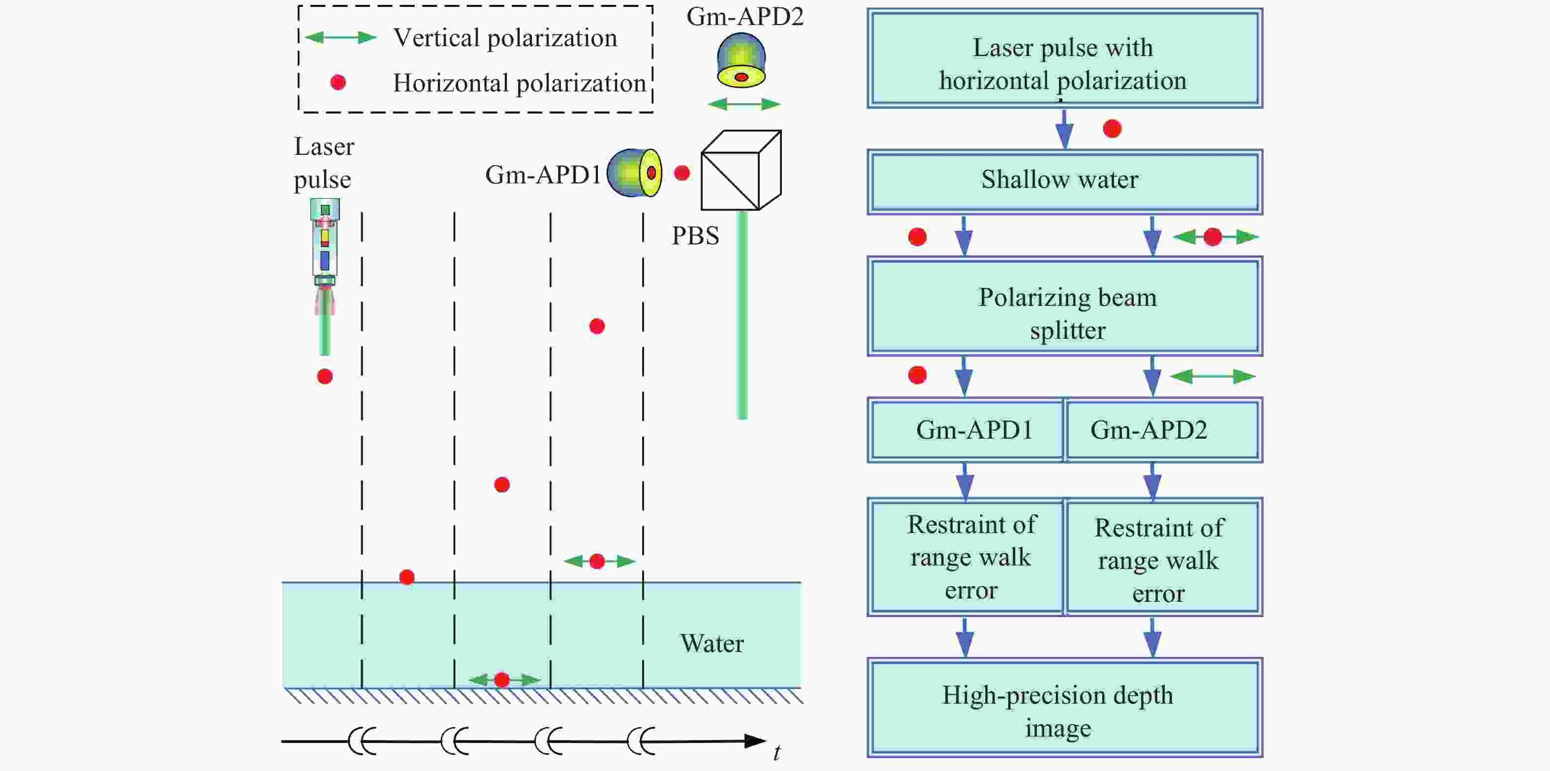
      Figure 1.  (a) Schematic diagram for realizing polarization splitting; (b) Flow chart of program

      偏振光在传输过程中,一般采用穆勒矩阵和斯托克斯参量来描述偏振态的变化[23]。笔者所在课题组统一规定水平方向表示为0°,并且始终沿着光束传播方向观察。那么,水平线偏振光的斯托克斯参量可以表示为${\left[ {\begin{array}{*{20}{c}} 1&1&0&0 \end{array}} \right]^{\rm{T}}}$,竖直线偏振光表示为${\left[ {\begin{array}{*{20}{c}} 1&{ - 1}&0&0 \end{array}} \right]^{\rm{T}}}$。对于起偏角为${\theta _p}$的线性起偏器,可以用穆勒矩阵${{{M}}_{{\rm{Pol}}}}\left( {{\theta _p}} \right)$表示;对于快轴方位角为$\;\beta $,延迟量为$\delta $的波片,可以用穆勒矩阵${{{M}}_{{\rm{VWP}}}}\left( {\beta ,\delta } \right)$表示,两者的具体表示如下:

      假设激光器产生的偏振态为${{{S}}_{{\rm{laser}}}}$,经过1/2波片和格兰泰勒棱镜之后,产生一束严格的水平线偏振光${{{S}}_T}$

      对于一些非偏振光学元件,例如反射镜、各种透镜和滤波片等,它们的退偏振效应忽略不计。而对于表面粗糙的物体,它们的退偏振效应较显著,甚至可能完全退偏。完整的穆勒矩阵可以描述三种偏振特性。双向衰减特性,它描述与偏振有关的强度衰减;相位延迟特性,它描述与偏振有关的位相变化;退偏特性,它描述偏振光退化为非偏振光的程度。在文中,笔者只考虑浅水层底面对入射光的退偏特性,衰减特性将包含在激光雷达方程中衰减系数中,见后文分析。那么,此时底面的穆勒矩阵就可以简化为一个标准化对角阵[23]

      经过前面的分析,大家知道Gm-APD1探测的是从浅水层水面反射回来的水平线偏振光信号。激光雷达能量方程表示激光器输入和探测器输出之间的能量衰减。对于一个实际的系统,在水平分量光路中,激光雷达能量方程的衰减为一个定值,假设为常数${G_1}$。那么,Gm-APD1探测到的为水平线偏振光分量,而且它的斯托克斯参量表示为:

      Gm-APD2探测的是从浅水层底面反射回来的垂直分量的信号光分量。同理,在垂直分量的光路中,激光雷达能量方程的衰减系数也为一个定值,假设为常数${G_2}$。实际上,衰减系数${G_1}$${G_2}$已经包含了前文中描述的目标的穆勒矩阵中的衰减特性。那么,此时,Gm-APD2探测到的垂直线偏振光分量的斯托克斯参量表示为:

      斯托克斯是一个间接测量值,需要根据直接测量值、强度值解算得到。强度值和斯托克斯参量的关系如下所示:

      公式(7)、(8)分别表示两个Gm-APD探测的信号,信号强度分别与各偏振支路的衰减系数有关。对于实际的系统,这两个衰减系数是一个常数。综上所述,从理论上分析了该光学系统能够在空间上实现超薄浅水层水面和底面信号的完全分离,并分别被两个Gm-APD探测,突破了激光脉冲宽度的限制。

    • 图1(b)为笔者提出方案的流程图,由于Gm-APD激光雷达存在距离漂移误差,将引起距离像的畸变,因此,必须对两个偏振支路的信号分别进行距离漂移误差抑制,从而获取浅水层的高精度距离信息。下面将介绍信号复原质心算法抑制距离漂移误差的原理。

      距离漂移误差存在,本质上是由于Gm-APD的非线性响应模型。根据Gm-APD的泊松概率响应模型[18],若在时间轴上对其分成若干个小区间,其在第i个子区间内的触发概率为:

      式中:${N_{sn}}\left( i \right) = {N_s}\left( i \right) + {N_n}\left( i \right)$${N_s}\left( i \right)$表示第i个子区间内的信号光电子数,${N_n}\left( i \right)$表示第i个子区间内的噪声光电子数;d表示Gm-APD的死时间长度所对应的子区间个数。

      根据统计学原理,在实验测量中,当探测次数达到一定数量时,触发概率可以由下式近似得到:

      式中:K(i)表示Gm-APD在第i个区间的雪崩次数,即Gm-APD在探测过程中直接输出的光子计数分布。笔者发现,输入和输出并不是一个线性关系。因此,如果直接采用光子计数分布去进行测距,必然存在误差,表现为距离漂移误差。详细的理论分析在笔者团队之前的研究工作[24-25]中已经阐述。

      鉴于此,笔者采用回波信号光电子数复原法[16],可以反推得到回波信号光电子数的分布${N_s}^\prime \left( i \right)$

      此时,光电子数分布与入射到Gm-APD的光信号呈线性关系,用其去表征信号不会引入距离漂移误差,从而实现距离漂移误差的抑制。

      对于信号区间${T_1} \sim {T_m}$内所有的信号光电子数${N_s}^\prime \left( i \right)$求和,可以得到入射光的强度信息为:

      对恢复后的回波信号光电子数分布${N_s}^\prime \left( i \right)$,采用质心算法,得到目标的飞行时间信息如下:

      式中:$\Delta t$为文中实验中光子计数板卡的时间分辨率,164 ps。

      Gm-APD1探测的浅水层水面的距离表示为:

      式中:$c = 3 \times {10^8}$ m/s,表示真空中的光速。

      Gm-APD2探测的浅水层底面的距离表示为:

      式中:n为水的折射率,$n = 1.333$

      综上分析,首先利用信号复原算法,根据Gm-APD的光子计数分布图恢复到信号光电子数分布图;再利用质心算法获取信号光电子数分布图的的质心,作为目标的激光脉冲飞行时间,从而获取距离值。采用信号复原质心算法进行数据处理后,从理论上能够避免距离漂移误差的引入,从而实现高精度的距离信息获取。

    • 图2表示文中设计的双Gm-APD光子计数偏振激光雷达系统示意图。信号发生器(Signal generator)产生一个2 kHz的TTL信号去触发激光器发射激光脉冲,激光波长为1064 nm,通过倍频晶体(FDC)转换为532 nm,也就是系统的工作波长。分束器(BS)将发射光分成两部分,其中一部分入射到高速PIN探测器,其输出作为光子计数板卡(DPC-230 Photon Correlator Card)的计时起始信号;另一部分激光通过1/2波片(HWP)和格兰泰勒棱镜(Polarizer)的组合,产生水平线偏振光,再经过X-Y扫描系统(X-Y scanning)照射目标。当水平线偏振光照射到浅水层时,将返回两束信号光。一束是从浅水层水面反射回的水平线偏振光,此信号较强;另一束是穿过水体后,从粗糙的底面返回的包含水平和垂直分量的信号光,此信号较弱。两束信号光全部经过接收光学系统(Receiving system)接收,采用窄带滤波片(NBPF)滤除杂散背景光,采用衰减片组(Attenuators)衰减成光子量级信号强度。信号光子经过偏振分光棱镜(PBS)偏振分光后分别采用光纤准直器(Optical fiber collimator)收集,Gm-APD1探测水平偏振分量的信号光子,Gm-APD2探测垂直偏振分量的信号光子被。光子计数卡采集两者的输出信号,获取信号光子计数分布图。采用信号复原质心算法抑制距离漂移误差后,由计算机(Computer)解算得到高精度距离信息并显示目标的距离像。

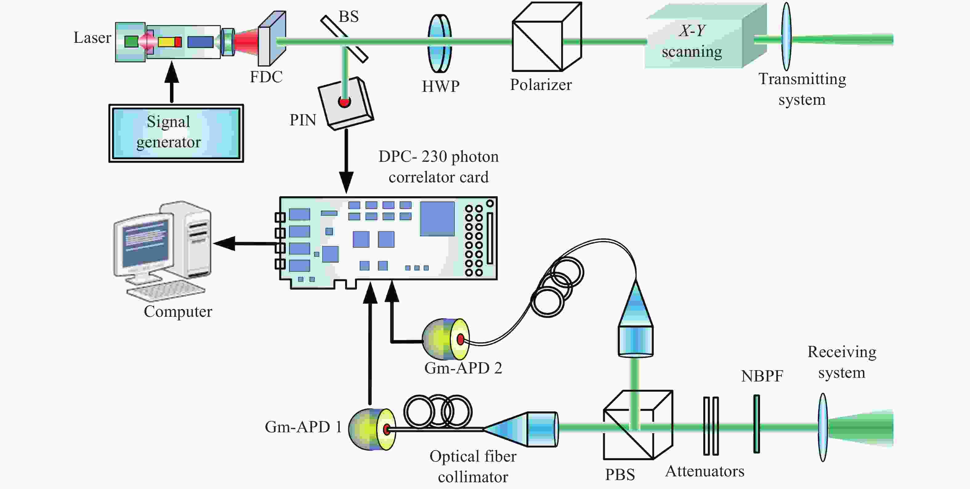
      Figure 2.  Schematic diagram of the double Gm-APDs polarization lidar system(FDC, Frequency doubling crystal; PIN, High-speed PIN detector; BS, Beam splitter; HWP, Half wave plate; Polarizer, Glan-Taylor prism; PBS, Polarization beam splitting prism; NBPF, Narrow band pass filter; Gm-APD, Gm-APD detecting module)

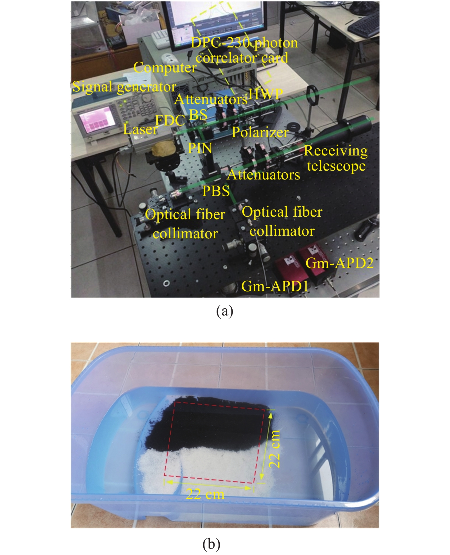
      图3(a)为在实验室内搭建的双Gm-APD偏振激光雷达系统。图3(b)为实验中的超薄浅水层目标,深度渐变,从4.5 cm变化到8 cm,并且底面覆盖了黑、白沙子,探测距离为5 m。实验中的扫描成像点数为44×44。文中实验中所采用的器件及其参数如表1所示。

      Figure 3.  (a) Double Gm-APD polarization lidar system in the laboratory; (b) Shallow water layer designed in the laboratory

      在调节水平线偏振态激光发射过程中,激光器发射的是某一线偏振态的激光,通过1/2波片去改变线偏振态方向,旋转1/2波片的快轴角度,使得出射的水平线偏振光的强度达到最大。这是为了提高激光的能量利用率,适应将来的远距离探测。

      DevicesPerformance parameters
      Semiconductor laser Wavelength, 1064 nm; Pulse width, 6 ns; Repetition frequency, 2 kHz; Work wavelength of the system, 532 nm.
      Receiving telescope Field of view, <70 mrad; Diameter of telescope, 50 mm.
      Gm-APD module Laser components GmbH, COUNT-100C-FC; Photon detection efficiency, 70%@532 nm; Dead time, 45 ns; Dark count rate, 100 Hz; Maximum count rate, 20 MHz; Temporal jittering, 1000 ps; Length of TTL output pulse, 15 ns; High level, 3 V.
      Photon correlator card Becker & Hickl GmbH, DPC-230; Collection time, 60 s; Operating mode,“Multicaler”; Time duration of time-bin, 164 ps.

      Table 1.  Performance parameters of the devices in our experiment

    • 文中实验中的数据采集部分在DPC-230光子计数板卡及其自带的软件中实现,数据处理部分及三维距离像的显示在MATLAB平台中实现。脉冲重复频率为2 kHz,单点测量时间为60 s,因此,单点的激光脉冲统计个数为1.2×10⁵个。

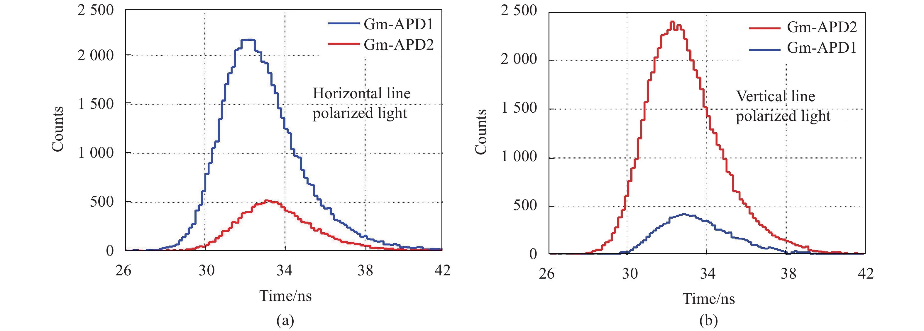
      图4表示发射不同线偏振态时,某个像素点的两个Gm-APD的光子计数分布图。图4(a)表示发射水平线偏振光时的探测器输出,此时,Gm-APD1探测前表面反射信号,信号较强;Gm-APD2探测后表面反射信号,信号很微弱。图4(b)表示发射垂直线偏振光时的探测器输出,此时,Gm-APD2探测前表面反射信号,信号较强;Gm-APD1探测后表面反射信号,信号很微弱。此结果表明,该系统在两个偏振方向均能实现两束光的偏振分离。

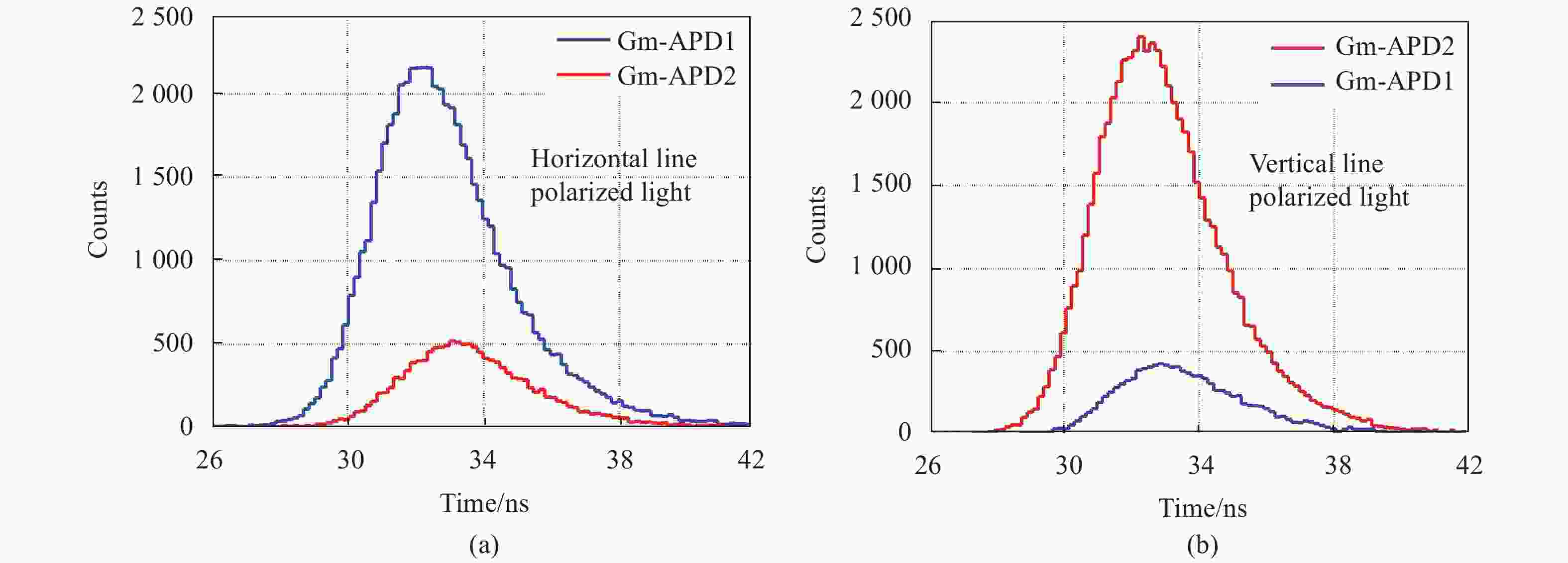
      Figure 4.  Photon counting distributions of the two Gm-APDs with different line polarized light on a pixel. (a) Horizontal line polarized light; (b) Vertical line polarized light

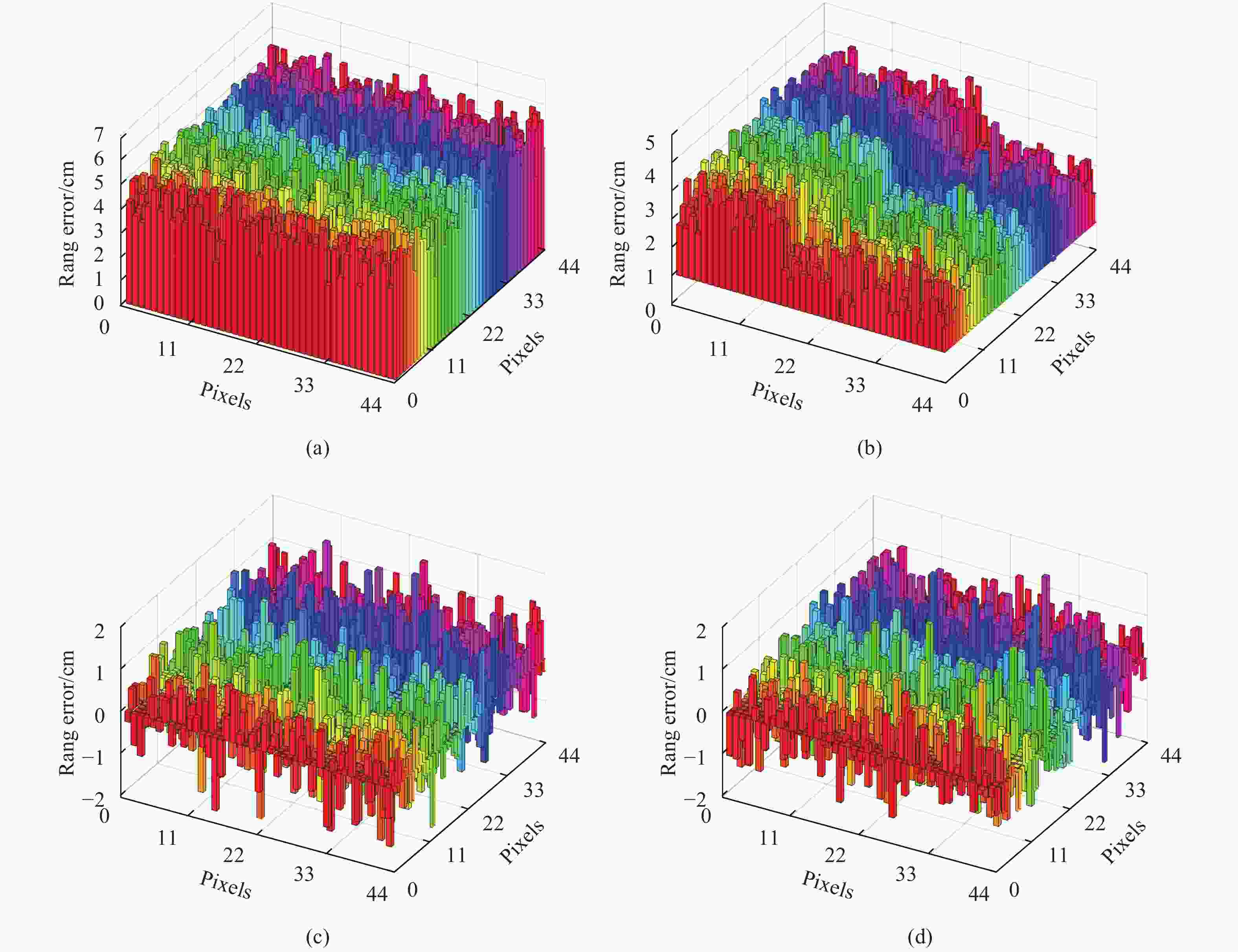
      图5为实验中采用双Gm-APD偏振激光雷达系统测量得到的浅水层图像,颜色表示距离值。成像像素点为44×44,水面到激光雷达系统的距离为500 cm,在图像中显示为“0 cm”,底面的距离显示为负数。浅水层底面覆盖了黑、白沙子,深度渐变,从4.5 cm变化到8 cm。图5(a)为距离漂移误差抑制前的浅水层距离像,图5(b)图5(a)在另一视角下的距离像。从图5(a)(b)中可以看出,浅水层的距离像发生了明显的畸变。水面的距离远离0 cm,这是由于水面的反射信号较强,距离漂移误差较大。底面的黑、白沙子理应是一个连续的斜面,但是,现在黑、白沙子之间存在着明显的断层。这是由于黑、白沙子的反射率存在较大差异,黑色沙子的反射信号弱于白色沙子的反射信号,因此,黑色沙子的距离漂移误差小于白色沙子,于是,距离像中存在了明显断层。图5(c)为距离漂移误差抑制后的浅水层距离像,图5(d)图5(c)在另一视角下的距离像。从图5(c)(d)中可以看出,此时浅水层的距离像能够很好地接近真实情况,距离漂移误差得到了很好的抑制。

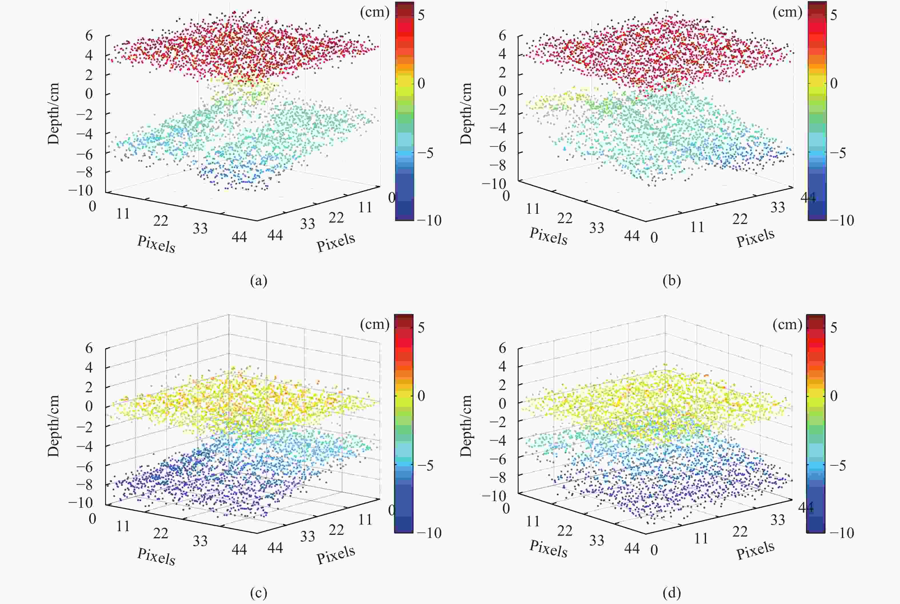
      Figure 5.  Depth image of the shallow water layer obtained in the experiment. (a) Before the restraint of range walk error; (b) Depth image under another view of (a); (c) After the restraint of range walk error; (d) Depth image under another view of (c)

      为了进一步分析图5中的实验数据,笔者将实验数据与真实值进行了比较,得到了实验数据点的距离误差分布直方图,如图6所示。笔者采用卷尺和卡尺测量的目标距离和水底的距离分布作为实验中的距离真值,测量误差大概在0.2 cm左右。图6(a)图5(a)中漂移误差抑制前的水面各像素点的距离误差分布直方图。图6(a)中表示水面的数据基本分布在同一水平面,平均值为4.5 cm,标准偏差为0.8 cm。说明此时水面的距离漂移误差为4.5 cm。图6(b)图5(a)中漂移误差抑制前的底面各像素点的距离误差分布直方图。图6(b)中的距离误差明显分成了两部分,白色沙子部分的平均值为2.8 cm,标准偏差为0.9 cm;黑色沙子部分的平均值为1.5 cm,标准偏差为0.8 cm。说明此时白色沙子的距离漂移误差为2.8 cm,黑色沙子的距离漂移误差为1.5 cm。图6(c)图5(c)中漂移误差抑制后的水面各像素点的距离误差分布直方图。图6(c)中的平均值为0 cm,标准偏差为0.8 cm。说明此时很好地抑制了距离漂移误差。图6(d)图5(c)中漂移误差抑制后的底面各像素点的距离误差分布直方图。图6(d)中数据的平均值为0 cm,标准偏差为0.8 cm。说明即使在不同反射率的斜面目标中,此时也能很好地抑制距离漂移误差。从图6(c)(d)中数据的标准偏差,笔者可以认为双Gm-APD偏振激光雷达的测距精度达到0.8 cm。

      Figure 6.  Histogram of range error distribution of experimental data points. (a) Pixels of the shallow water surface in Fig.5(a); (b) Pixels of the bottom surface in Fig.5(a); (c) Pixels of the shallow water surface in Fig.5(c); (d) Pixels of the bottom surface in Fig.5(c)

      从理论的偏振分光原理出发,不存在浅水层深度的下限,即使是几mm的浅水层也是能够完成偏振分光的。但是,真实的探测系统存在着测距精度,文中的实验结果为0.8 cm。也就说,0.8 cm的测距精度限制了系统的极限分辨率0.8 cm,也同样限制了浅水层的深度0.8 cm。对于0.8 cm深度以内的浅水层,文中目前所采用的硬件是无法实现的,前后表面的距离值将发生重合。该测距精度将限制系统的距离分辨为0.8 cm,即最小可探测的浅水层深度为0.8 cm。

    • 文中设计了一个双Gm-APD偏振激光雷达系统,可以采用宽脉冲实现超薄浅水层的测量。利用浅水层水面和底面两者不同的退偏特性,发射系统发射水平线偏振光,接收系统采用偏振分光棱镜将水面和底面的发射光进行偏振分离,各支路分别采用Gm-APD探测接收,从而获取水面和底面的距离信息。利用偏振分光棱镜将原本在时域上紧密堆叠的两个信号,从空域上实现了完美分离,从而突破了激光脉冲宽度的限制。在此过程中,笔者采用信号复原质心算法抑制距离漂移误差,矫正了距离像的畸变,获取了浅水层高精度的距离像。文中首先从理论上论证了偏振分离水面和底面信号光的可行性,阐述了信号复原质心算法及其抑制距离漂移误差的基本原理。然后,通过实验测量所设计的浅水层目标,从实验上验证了该方案的可行性。最后,通过实验数据的分析,得出双Gm-APD偏振激光雷达的测距精度达到0.8 cm。该方案能够为机载海洋测绘激光雷达的浅水层测量提供一定借鉴意义。

      水质实际上影响着水体的偏振特性,如果水体浑浊,水体中颗粒物将会对激光发生严重的散射和退偏,此时将会影响底面反射光的偏振分离。因此,未来可以开展不同水质条件下所提出方案的可行性研究。目前实验中的方案采用2 kHz单脉冲累积,成像帧频很慢,与实用化相比,存在一定的不足。未来可以采用高重频激光器,并进行脉冲编码,能够提高成像帧频并适应实际应用条件。

Reference (25)

Catalog

    /

    DownLoad:  Full-Size Img  PowerPoint
    Return
    Return