


-
空间碎片通常认为是地球轨道上在轨运行或再入大气层的无功能的人造物体及其残块和组件。随着人类航天活动的不断增加,卫星解体与撞击产生的碎片数量逐年增多。空间碎片的存在严重地威胁着在轨运行航天器的安全,不论是被动规避还是主动清除,对于空间碎片位置和形状的探测都是十分必要的[1]。
由于大气与云层很大程度上限制了地基的探测精度,通常选择天基系统直接对空间轨道上的碎片进行探测。相对于发达国家,我国对空间碎片天基光学监视技术的研究较晚。中国科学院国家天文台研制出了一种高精度和强光力的空间碎片探测望远镜。中国空间技术研究院提出了使用天基光学望远镜对直径小于10 cm的空间碎片探测的卫星方案和相关指标体系结果。目前,国防科技大学、南京大学、哈尔滨工业大学和一批科研院所对天基光学探测空间碎片技术研究也有了突破性进展[2]。2015年6月8日,国家航天局空间碎片监测与应用中心在中国科学院国家天文台挂牌成立。2016年,中国科学院紫金山天文台分别对地球同步轨道和近地轨道碎片进行了天基光学观测的平台设计方案[3]。文中基于空间碎片探测“三合一”的系统方案[4],针对工作温度10~30 °C、尺寸限制、安装面距离重心过远的问题设计了空间碎片探测与测距复合系统光学望远镜。
-
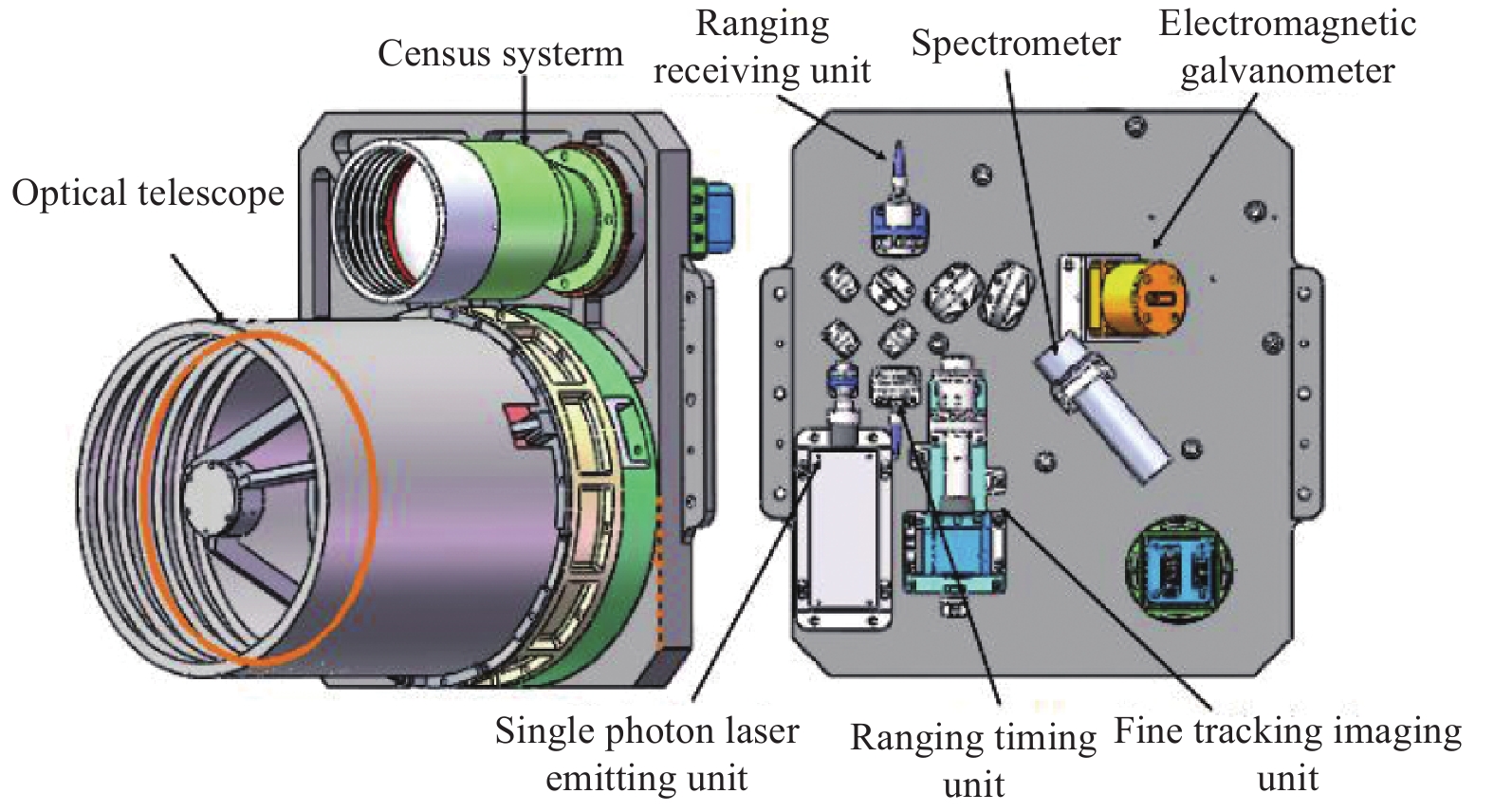
空间碎片测距与成像复合系统如图1所示,其中主要由光学望远镜、碎片普查单元、精跟踪成像单元、单光子激光测距发射单元、测距计时单元、激光测距接收单元、光谱探测单元、精跟踪振镜、光谱分光镜、能量分光镜以及反射镜组成。

Figure 1. Space debris ranging and imaging composite system
-
整体光路原理如图2所示:搜索阶段,使用普查系统与转台对碎片所在的不确定区域进行扫描,发现初步位置,由信息处理分系统发出驱动指令,由转台分系统接收指令,进行指向;指向与粗跟踪阶段,根据普查相机中目标的位置驱动转台进行精确指向,根据目标脱靶量,确定转动角度、速度,进行稳定跟踪,令目标一直保持在精跟踪视场内。
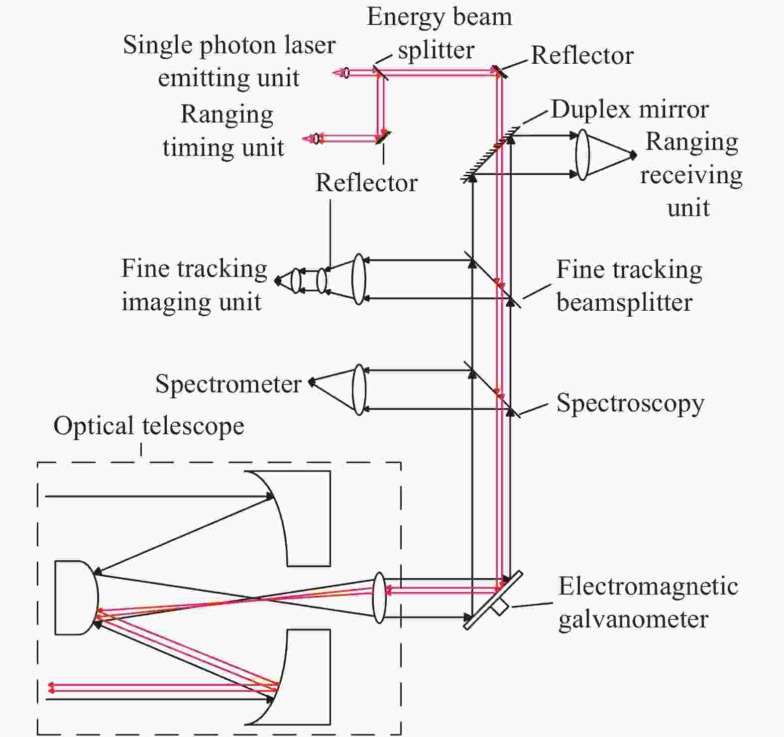
Figure 2. Principle diagram of the optical path of the space debris detection and ranging composite system
精跟踪阶段,根据精跟踪相机CCD视场内接收到碎片的反射光,利用电磁快反镜补偿转台粗跟踪的残差,实现稳定跟踪,令碎片目标稳定跟踪在光谱探测与测距的有效区域内。
测距与探测阶段,测距发射单元发射激光脉冲,利用测距计时单元与测距接收单元测量发出与回波的时间,计算碎片的距离信息。同时根据精跟踪视场内目标光斑所占像元数的数量及位置,计算碎片的大小与形状,配合使用光谱仪进行目标碎片的光谱信息的探测,确定碎片的材质与物理特性[5]。
在空间碎片测距与成像复合系统中,光学望远镜不仅起到了光束缩束作用,而且决定着整个系统的成像质量[6]。但由于现有转台对光学基台尺寸限制以及对光学望远镜进行尾部安装的特殊要求,导致重心距望远镜安装面过远,大大增加了其设计难度,对其在装调、检测、室外实验验证期间的性能提出更严峻的要求。另外系统需要兼顾可见光与中波红外双波段,因此具体技术指标如表1所示。
Item Technical index requirements Effective aperture of optical system 250 mm Surface accuracy RMS of main mirror assembly ≥λ/40 System wave aberration RMS ≥λ/10 Primary and secondary mirror spacing error ≤0.02 mm Primary and secondary mirror tilt ≤3″ Secondary mirror and bracket blocking ratio ≤7% Optical antenna fundamental frequency ≥120 Hz Optical antenna quality ≤10 kg Table 1. Technical specificatons optical telescope
-
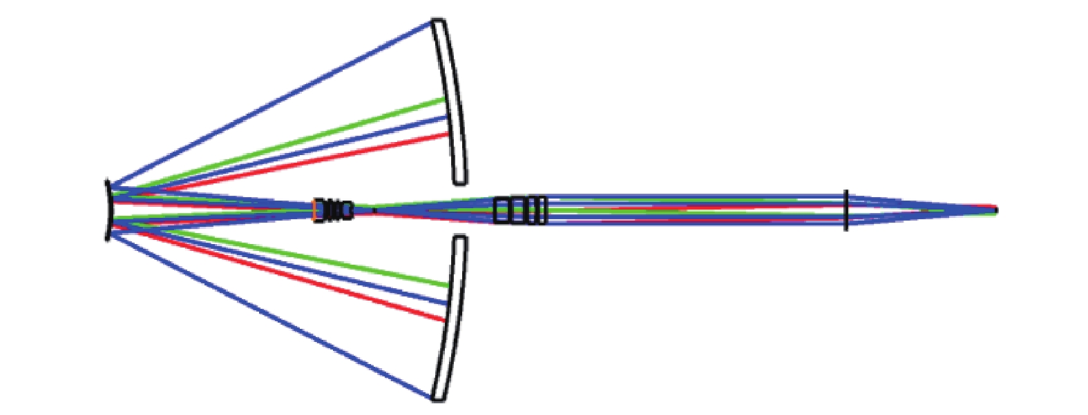
为了减小系统的尺寸和复杂度及方便设计,光学系统的望远单元采用发-收共用卡塞格林系统,测距与成像复合系统光学望远镜设计结构形式为:主镜为抛物面,次镜为双曲面。主镜通光口径250 mm,次镜通光口径40 mm。选择波长1064 nm的激光作为测距光,400~700 nm的自然光作为碎片普查与精跟踪成像和光谱成像光。
望远系统视场由系统中视场最大的子光路决定,即偏振光谱成像子光路,其视场角为4°。由于整个系统是一个光束缩放系统和后方子光路的结合体,光束缩放系统的大口径端,即卡式系统前端的视场角应为偏振光谱成像子光路的视场角除以缩放倍率,望远单元放大倍率为14.04倍,因此卡式系统视场角为0.28°。其中三镜共包含8片透镜,,光学玻璃用于校正色差与像差。其光学结构如图3所示。

Figure 3. Optical structure of telescope structure system
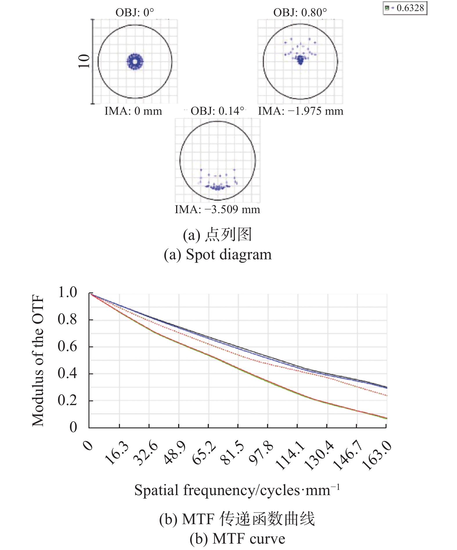
如图4(a)所示,艾里斑直径4.352 μm且系统光斑均在艾里斑直径内,满足精跟踪使用要求。光学系统调制传递函数(MTF)曲线如图4(b)所示,可以看出,系统的成像质量接近衍射极限[7]。

Figure 4. System image quality evaluation
但由于系统的出瞳大概在准直镜后面288.27 mm处,系统的出瞳和后面子光路的入瞳,其光阑不匹配会导致视场切割,边缘视场照度下降而且像质变差。需要保证从准直镜最后一片镜子到碎片成像和精跟踪子光路的第一片镜子,其总距离为283.27 mm (除去了窄带滤光片占的位置)或接近这个数值,又由于现有设计转台对光学基台整体尺寸限制为450 mm×400 mm、光路排布方式要求以及转台俯仰角的限制,导致光学望远镜安装方式为尾部固定在光学基台背板上,从而重心位置距离安装面过远,产生悬臂梁,进而影响成像质量。因此针对光学望远镜尾部安装问题进行针对性的结构设计分析,并验证其可靠性[8]。
-
光学机械结构件常用材料如表2所示。光学望远镜结构件选择主要从材料的力学性能及热稳定性等来综合考虑。一般主要选用高比刚度以及热稳定性系数大的材料。国内外常用铍、铝、微晶玻璃、碳化硅作为镜坯材料。作为反射镜材料的备选,表2给出了反射镜以及主镜支撑组件候选材料属性。
Material $\rho /{g}\cdot {\rm cm}^{-3}$ $ E/\rho $ Thermal stability $ \mu $ $ \mathrm{\alpha }/ $℃ Zerodur 2.53 3.58 32.8 0.23 0.05$ \times {10}^{-6} $ Be 1.85 15.6 19.12 0.26 11.3$ \times {10}^{-6} $ RB-SIC 3.5 10.6 60.7 0.29 2.6$ \times {10}^{-6} $ Al 2.68 2.55 7.1 0.33 23.6$ \times {10}^{-6} $ ULE 2.21 3.08 87.3 0.17 0.015$ \times {10}^{-6} $ TC4 2.53 4.44 29.49 0.23 8.9$ \times {10}^{-6} $ 4J32 8.1 17 46.33 0.26 0.3$ \times {10}^{-6} $ 4J36 8.05 18 8.25 0.29 1.26$ \times {10}^{-6} $ 2A12 2.9 27 7.1 0.33 23.6$ \times {10}^{-6} $ 60SiC/Al 3.02 71 25.88 0.17 8.5$ \times {10}^{-6} $ Table 2. Material properties of optical telescope
结合该系统地面演示验证实验工作环境要求,对于主镜材料来说,SiC材料虽然比刚度高且热稳定好,但硬度大,光学抛光周期长、成本高,ULE低膨胀玻璃特性略逊于ZERODUR;望远镜孔径为250 mm,外场试验温差大,因此在设计过程中,必须考虑其轻量化以及热稳定性[9]。ZERODUR微晶玻璃具有良好的热稳定性与较低的密度,其光学加工性能、机械加工性能与稳定性综合对比相对较好,因此综合考虑选用ZERODUR微晶玻璃作为主镜与次镜的镜体材料[10]。
-
根据主镜支撑位置的方式不同,主镜支撑可分为中心支撑、周边支撑以及背部支撑三种方式,考虑到地面演示验证时外场环境多变,温度不稳定,主镜对温度的变化十分敏感,因此采用中心单点支撑方式。当环境温度变化时不会像多点支撑以及周边支撑发生热变形导致相互干涉。另一方面在安装调试阶段,中心支撑的反射镜自由度更高,降低了光学装校精度的要求,可以大大简化支撑结构的设计,中心支撑结构如图5所示。在结构材料的选择上,为了避免由于材料膨胀系数不匹配对面型精度的影响,铟钢(Invar4J32)材料线膨胀系数可调, 能够调整到与ZERDUR材料的线胀系数只差0.2×10⁻⁶/℃,因此与微晶粘接的锥套选用线膨胀系数可调的铟钢(4J32),保证主镜组件的结构轻量化,与铟钢连接的柔性支撑采用比刚度较好、线膨胀系数相对较低且更适合作为柔性支撑结构的钛合金[11]。

Figure 5. Structure diagram of the main mirror assembly
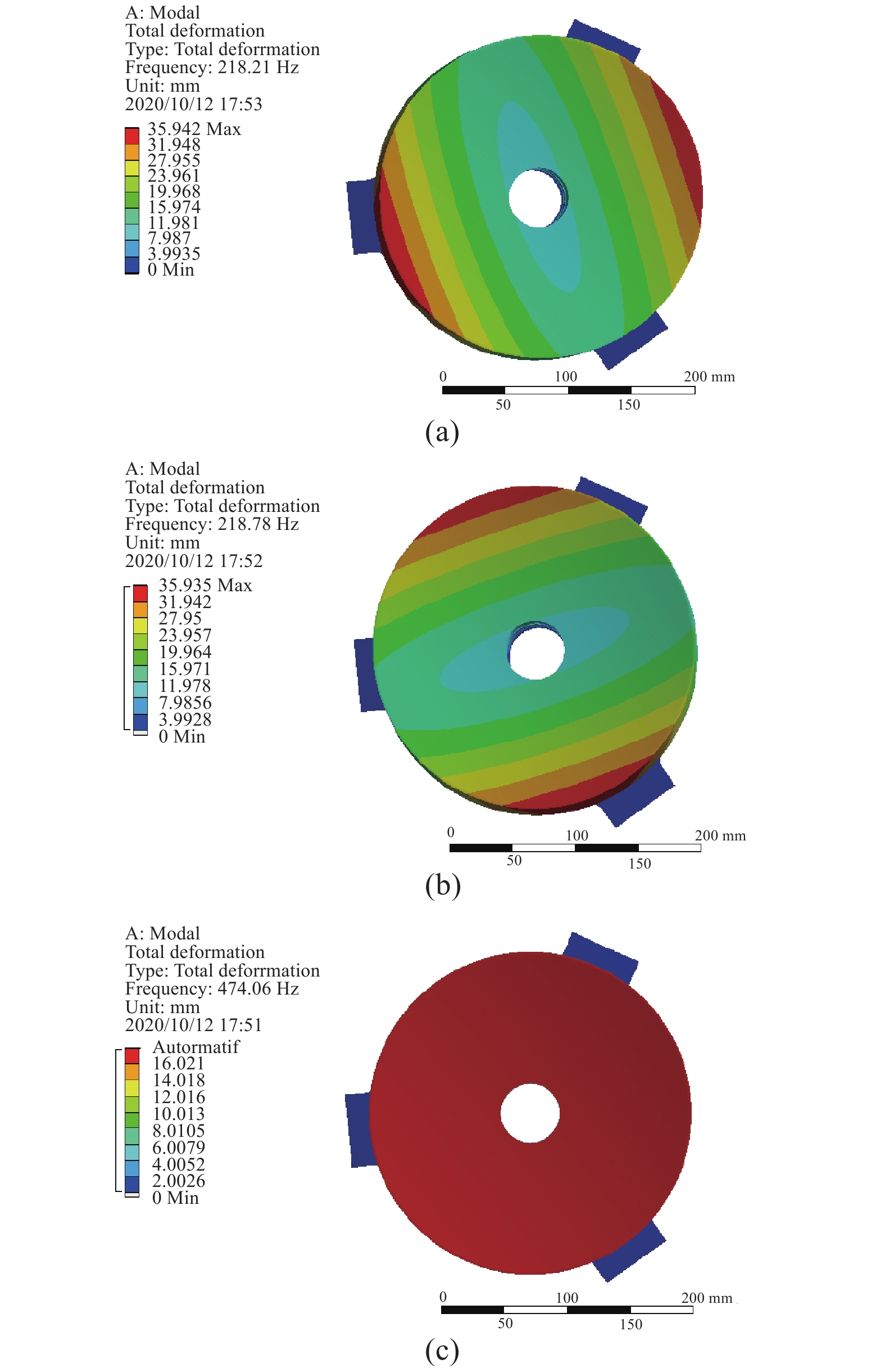
主镜作为光学望远镜的核心组成部件,其安装、装配及定位精度将直接影响反射镜的面型,从而影响探测的成像质量。为保证在外场试验条件下主镜面型仍满足指标要求,主镜柔性支撑结构作为连接安装背板与主镜体的主要部件,必须具有良好的动、静态力学性能和热性能,能够很好地吸收、隔离安装应力以及温度变化产生的应力,以保证环境条件变化时反射镜具有足够好的稳定性。将主镜组件在(20±10) °C条件下的面型误差RMS值、主镜组件的固有频率作为设计指导,采用径向与轴向双向开槽方式,如图6所示,法兰轴向开槽,隔离安装应力,侧壁径向开槽隔离热变形应力,进一步提高了支撑结构对于应力的隔离与吸收[12]。根据圆弧形柔性支撑结构转动刚度的计算公式[9]以及利用ANSYS对主镜组件进行模态和热力学分析确定柔性支撑参数如下:安装法兰切口深度为1.5 mm,柔性支撑环形槽口宽度为2 mm,切槽角度为80°,对主镜组件进行热力耦分析,在(20°±10) °C以及光轴方向1 g重力条件下,主镜组件的面型误差与最大变形量如图7所示,面型误差RMS值为λ/52,最大变形量为0.0045 mm。对主镜组件进行模态分析,前三阶模态结果如图8所示,其中一阶频率为218 Hz,主镜组件满足系统刚度以及面型误差要求。

Figure 6. Flexible support
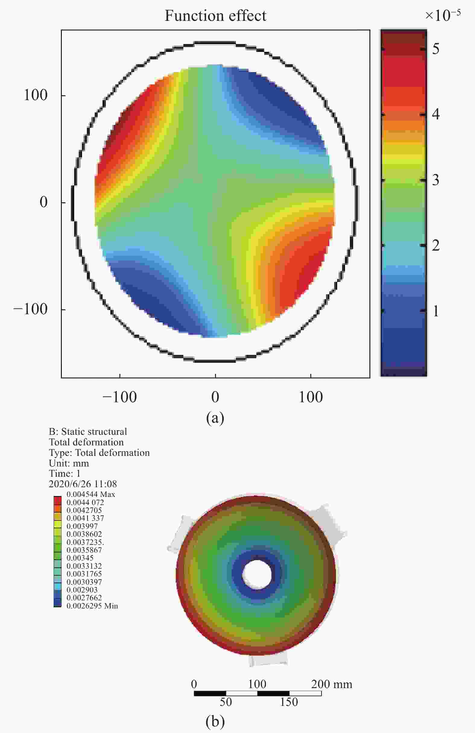
Figure 7. RMS value analysis result of the surface error of the main mirror assembly

Figure 8. First three modes of the primary mirror assembly
-
反射镜的径厚比直接影响镜体的力热稳定性及轻量化程度,镜体太薄会导致整体刚度小,易发生弯曲;镜体太厚使质量过大,不利于轻量化。主镜背部轻量化形式主要有三角形蜂窝板、圆形蜂窝板、正六边形蜂窝板,如图9所示。

Figure 9. Lightweight hole model of main mirror
该系统通光口径为250 mm,实际设计的外径应比光学设计尺寸单边多5 mm用作加工余量。因此设计主镜直径为260 mm。对于近圆形反射镜:
式中:δ表示反射镜最大自重变形(µm);D表示圆盘半径;E表示材料杨氏模量;q表示每单位面积的负载;v表示材料的泊松比;总负荷可表示为qπD2/4。
对于指定材料,反射镜的刚度正比于h2/D2,即:
从公式(1)中可以看出,反射镜的自重变形与镜厚比及反射镜外径的平方成正比,与材料的杨氏模量成反比,因此确定镜厚比要根据实际情况以及经验性去选择设计,根据经验公式(1)确定厚度为40 mm,此时镜厚比为1∶6.5,并考虑到背部支撑筋布置和中心支撑孔直径,选定加强筋板内切圆直径为26 mm,背部加强筋板厚度t=5 mm。在其蜂窝板结构单元内切圆相同的情况下,对比三种轻量化形式下的模态与主要质量参数,选择刚度好、稳定性强的轻量化形式[13]。
在加工过程中,为了使反射镜单个蜂窝单元的最大变形量达到一个允许的值,必须设计相应的镜面厚度
$ {t}_{f} $ ,由Vukobratovich的推论可知:式中:δ为单个蜂窝单元的最大变形量,取 δ=λ/14(λ=632.8 nm);φ为与反射镜蜂窝单元形状有关的形状因子,取三角形φ1=0.0051,圆形φ2=0.00123,六边形φ3= 0.00111,υ−材料泊松比,取 υ=0.24;E为材料弹性模量,取 E=90.6 GPa;P为抛光压力,取P=67 kPa;b为加强筋板内切圆直径,b=26 mm。
将上述代入公式(3)计算,为了满足单个蜂窝单元的最大变形量δ≤λ/14(λ=632.8 nm),计算得到各轻量化形状最小厚度如表3所示,为了保证主镜具有足够的刚度和稳定性,选取镜面厚度为10 mm,利用有限元软件ANSYS对其三种轻量化结构形式进行模态分析,结果表明:三角形轻量化形式相比于圆形蜂窝板和正六边形型蜂窝板结构形具有更好的固有频率,随着模态阶数的增高,三角形结构形式的镜片在振动特性上相对其他两种形式镜片稳定性的优势更加明显。图10所示为三种不同形状的轻量化模型的前三阶模态,并将其用曲线形式进行更为直观的表达。
Structure type Triangle circle Hexagon Minimum thickness/mm 8.9 9.2 9.5 Table 3. Minimum panel thickness required for different lightweight structures

Figure 10. Model comparison under different lightweight shapes
通过分析结果(表4)可以看出,三角形轻量化形式相对于其他俩种结构形式质量和体积稍大,但是三角形的模态比其他俩种形式要高很多,说明随着模态阶次的提高,三角形结构的稳定性以及振动特性比其他两种形式的优势更加明显,因此采用三角形蜂窝单元对主镜进行轻量化设计。
主镜加工后采用环氧胶对主镜粘接锥套,对主镜组件进行面型检测,如图11所示,面型误差RMS值为λ/50,满足系统波像差要求。
Structure type First-order mode Second-order mode Third-order mode Quality/kg Lightweight rate Volume/mm3 Surface area/mm2 Triangle 2290.3 2290.5 2976 2.492 40.62% 9.95e+05 2.57e+05 Circle 2005.4 2010.2 2698 2.422 42.28% 9.58e+05 2.15e+05 Hexagon 1870.4 1890.6 2501 2.401 42.72% 9.54e+05 2.02e+05 Table 4. Lightweight analysis results of main mirror

Figure 11. Surface inspection result of main mirror assembly
-
针对光学望远镜尾部安装难点,次镜组件的位置稳定精度至关重要,同时次镜的稳定性也严重影响着系统的成像质量。因此对比次镜结构发现,三杆桁架与四杆桁架的次镜支撑方式在次镜刚体位移、倾角及轴向位移区别较小,三杆桁架比四杆桁架遮光率可降低9%左右,且该系统设计采用一体式次镜桁架,如图12所示:采用一体式结构能够有效提高次镜组件的整体刚度,同时加工时能够保证次镜室与主镜室安装位置的同轴度,并且选用铟钢(4J32)材料保证工作环境发生变化时主次镜间距变化最小,大大加强了次镜组件的刚度及稳定性,因此根据该系统的像质指标要求,选用次镜支撑三杆桁架。次镜组件中,次镜室同样采用铟钢材料与之匹配。次镜室轴向通过三个螺钉安装在次镜架上,通过修研垫片调节次镜的角度和位置。次镜室在径向通过次镜架上的四组主注胶孔与丝孔调节次镜的径向平移以及二维平移,调节完成后灌胶固定。

Figure 12. Secondary mirror assembly structure
-
由以上对主镜组件、次镜组件以及主镜室、背板等的结构初步设计如图13所示,进一步进行轻量化,包括主镜采用三角坑减重等,优化后光学望远镜整机质量为9.4 kg。
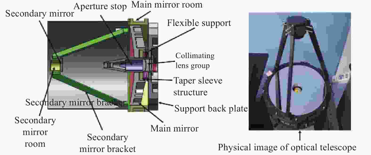
Figure 13. Structure diagram of optical telescope
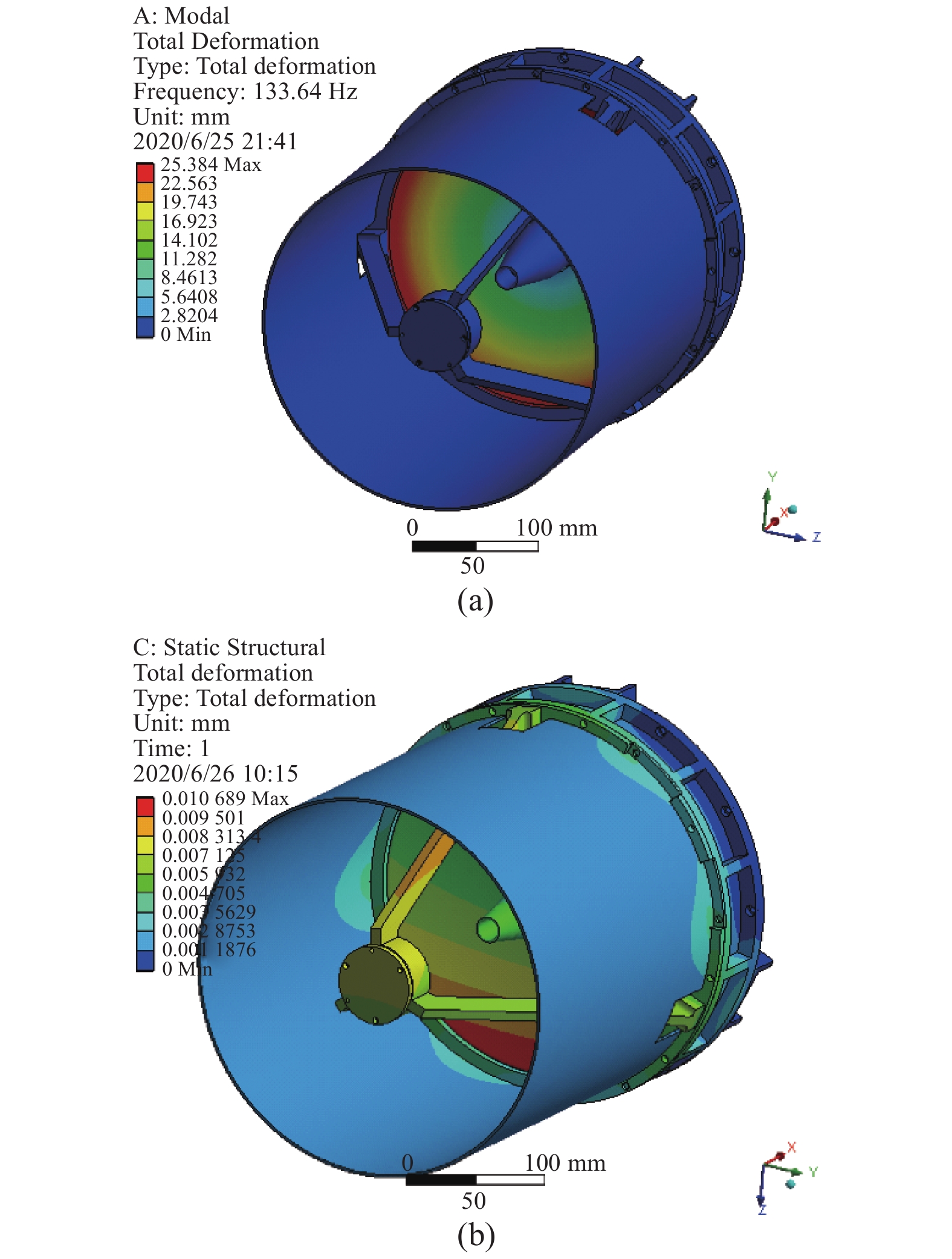
为验证设计的可行性,对光学望远镜整机建立ANSYS有限元分析模型,为了分析结果留有余量,将铟钢与微晶玻璃线膨胀系数差值设置为0.5×10⁻⁶/℃,实际为0.2×10−6/℃,整机光学望远镜划分了122170个六面体单元,共 46 003个节点数用于模态与热力耦分析。模态分析结果如图14所示,结果表明:光学望远镜一阶模态133 Hz,具有较好的动态刚度,满足光学载荷的要求。对光学望远单元进行热力耦分析,设置温度在(20±10) ℃,沿光轴方向1 g重力下,结果最大变形量为0.01 mm满足主次镜间距要求,成像质量好。

Figure 14. Simulation results of the whole machine
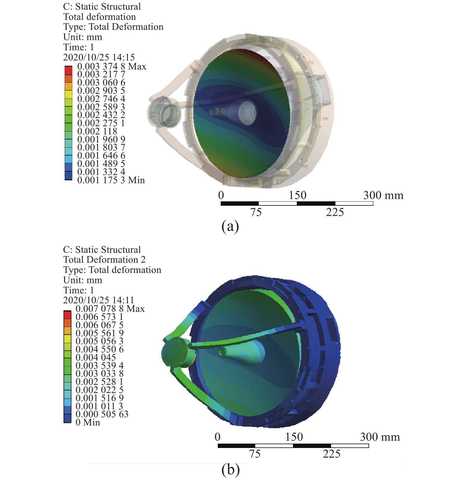
由于光学望远镜安装固定位置在光学天线尾部,产生了悬臂的现象,故要对其进行尾部固定约束,且1 g重力方向为垂直光轴方向,进行热力耦分析。实验结果如图15所示。主次镜最大间距为0.007 mm,镜面最大变形为0.003 mm,比沿光轴重力方向光学性能更好,满足系统指标要求。将镜面节点变形情况导出进行Zernike多项式拟合,如图16所示。在(20±10) ℃变化范围,沿光轴1 g自身重力下,整机系统面形精度RMS 值为λ/15,次镜最大倾角1.93″,主次镜间距最大0.01 mm。最大应力远小于材料的破坏强度,能够满足光学望远镜装校、检测以及在外场试验时的性能要求。

Figure 15. Simulation results of the tail installation of the whole machine
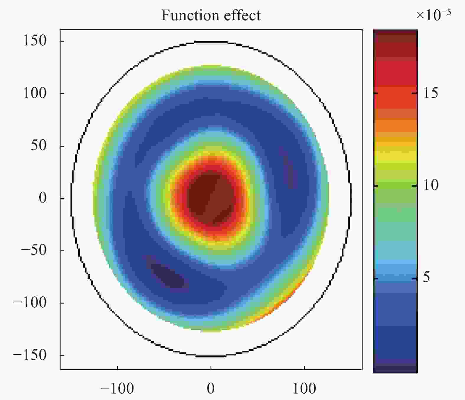
Figure 16. Surface fitting results
-
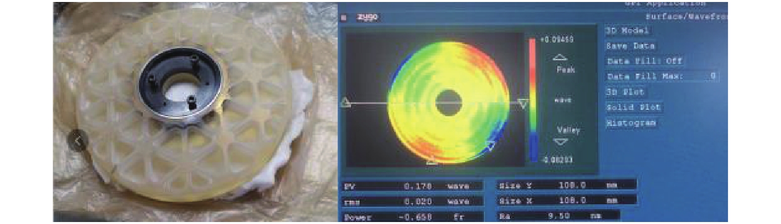
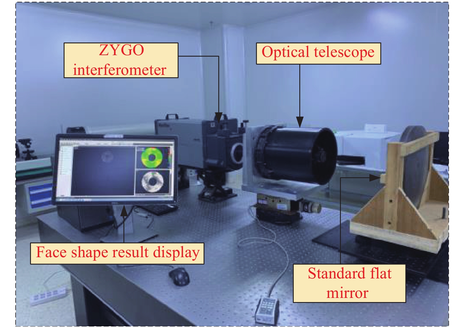
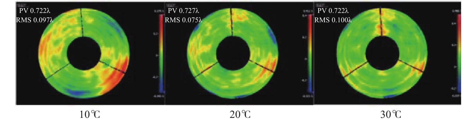
由于地面演示验证时外场环境多变,温度较不稳定,对于光学望远镜在10~30 ℃工作环境之间,系统仿真结果需要验证,因此使用ZYGO干涉仪,对在10、20、30 ℃温况下对光学望远镜系统进行波像差检测,检测现场如图17所示。保证ZYGO干涉仪与标准反射镜同轴,避免引入额外像差影响检测结果的准确性。检测结果如图18所示,在垂直于光轴1 g重力以及10、20、30 ℃条件下,RMS值为0.097λ、0.075λ、0.1λ,PV值为0.722λ、0.727λ、0.722λ,与仿真结果接近,能够满足空间碎片探测与测距复合系统对于光学望远镜RMS值优于λ/10的指标要求。

Figure 17. Testing site

Figure 18. Test of the optical telescope surface shape error
-
文中针对空间碎片探测与测距复合系统地面验证实验中,工作环境温度10~30 ℃、光学设计结构特殊性、转台包络尺寸限制导致望远镜重心距离安装面过远的问题,对空间碎片探测与测距复合系统中的光学望远镜进行了针对性设计,加强了次镜支架的整体稳定性以及主镜组件的隔离吸收应力和应变的能力。建立了主镜组件以及整机的有限元模型,模态分析结果显示主镜组件一阶模态频率为218 Hz,整机光学望远镜一阶模态频率为133 Hz,在温度(20±10) ℃、尾部固定约束条件下、重力沿光轴方向时,主次镜间隔最大误差0.01 mm,重力沿垂直光轴方向时,主次镜间距为0.007 mm,能够满足主次镜间距要求。使用泽尼克多项式对镜面面型误差进行拟合,仿真结果表明,在(20±10) ℃范围内主镜组件面型误差RMS优于λ/52,整机系统波像差RMS值优于λ/15,次镜倾斜1.93″,优于光学系统对光学望远镜的各级指标要求。使用ZYGO干涉仪对光学望远镜进行波相差检测,检测结果表明:室内温度在(20±10) ℃范围内,系统波像差优于λ/10,能够满足空间碎片探测与测距复合系统的地面验证实验使用要求。文中采用的光学望远镜设计方案能够达到设计指标要求,为空间碎片激光测距与成像以及通信三合一复合功能探测的下一步工作奠定了基础。
Optical telescope of space debris detection and ranging compound system
doi: 10.3788/IRLA20200464
- Received Date: 2020-11-23
- Rev Recd Date: 2021-02-20
- Publish Date: 2021-07-25
-
Key words:
- space debris /
- ranging and imaging compound system /
- optical telescope /
- simulation analysis
Abstract: In the ground verification demonstration experiment of the space debris detection and ranging composite system, the working environment is 10-30 ℃, the size limit of the optical base station (not exceeding 450 mm×400 mm) and the installation of the tail of the optical telescope cause the center of gravity to be far away from the mounting surface. Design of optical telescope for space debris detection and ranging compound system was proposed. The finite element model of the optical telescope was established by using ANSYS finite element analysis software. The analysis was carried out under the conditions of ambient temperature of 10-30 ℃, tail installation, optical axis direction and vertical optical axis direction of 1 g (g = 9.8 m/s2) gravity acceleration. The analysis results show that the first-order mode of the optical telescope is 133 Hz and the dynamic stiffness is better. When the gravity is in the direction of the optical axis, the maximum change in the distance between the primary and secondary mirrors is 0.01 mm. When the gravity is perpendicular to the optical axis, the maximum distance between the primary and secondary mirrors is 0.007 mm. The RMS value of the wave aberration of the optical telescope system is λ/15, and the maximum inclination angle of the secondary mirror is 1.93″. It has good power and thermal stability and can meet the index requirements in the process of optical antenna installation, calibration, testing and field experiment verification. After the optical telescope is assembled and calibrated, the image quality of the optical telescope is tested using a ZYGO interferometer. The test is performed under the conditions of gravity perpendicular to the optical axis and ambient temperature of 10 ℃, 20 ℃, and 30 ℃. The results show that the RMS value of the system wave phase difference is respectively at 0.097λ, 0.075λ and 0.1λ, the RMS value of the wave phase difference of the whole optical telescope system is better than λ/10 at the lowest temperature and the highest temperature, and all meet the requirements of the system.


 DownLoad: