


HTML
-
随着空间站的建立、探月工程的成功,我国对太空的探索取得了一个又一个的重大突破,在不断探索太空奥秘的同时,也面临着失重、高真空、太空辐射等环境带来的挑战。未来,仅依靠航天员进行太空探索将受到很多限制,因此,空间机械臂在航天工程中越来越受到重视,世界各国也正考虑用空间机械臂协助甚至取代宇航员进行太空作业,如协助卫星入轨、回收故障卫星、维修故障航天器、对大型航天器进行装配、完成空间站对接等。机械臂在进行太空作业时,需要借助视觉系统获取对目标进行准确定位并完成抓捕,其中双目视觉系统包含左目和右目两台相机,双目视觉测量方式不但可以有效地提高测量精度,支持对非合作目标的三维测量,同时还兼具单目视觉测量备份的功能,即使在两台相机中的一台无法正常工作的情况下,依然可以正常运行[1-3]。
在机械臂双目视觉系统中,相机的内参(相机的基本参数)和外参(相机之间的相对位置参数)的精确性往往决定了机械臂获取合作目标的精度[4-5]。传统的内外参标定技术通常采用黑白棋盘格作为标定目标,其中黑色方格与白色方格尺寸需要相同,所有方格尺寸一致,由于国内在光刻工艺上与国外先进水平仍存在一定差距,因此棋盘格在加工过程中往往会产生较大的误差无法消除;其次,由于棋盘格为二维,其相对于三维物体会缺少一部分信息,因此为了得到高准确度的相机参数,相机在标定过程中需要多次改变棋盘的方位,确保标定板在图像中能够覆盖整个视野并且覆盖较大的深度,测试过程繁琐。
针对传统相机内外参标定技术存在的精度低、操作繁琐等问题,文中提出了一种机械臂双目视觉系统内外参高精度标定方法,采用三维靶标场作为标定目标,三维靶标场分前、中、后共三层,每层布设14根矩形管,采用6 mm反光型摄影测量标志,在每层矩形管的同一方向上均匀布设,并将高精度测角设备经纬仪作为精测基准,通过坐标转换解算分步得到相机的内外参数,该方法对靶标场的制作工艺要求低,且拍摄过程不需要挪动靶标场位置,只需要被测相机在不同角度对靶标场拍照,操作简单,不受靶标场加工工艺的影响,有较高的引出精度。标定结果均满足机械臂双目视觉相机获取合作目标三维位姿的测量精度要求。
-
双目视觉系统由左目、右目两台相机组成,其往往安装在机械臂的顶端,如图1所示。

Figure 1. Binocular vision system
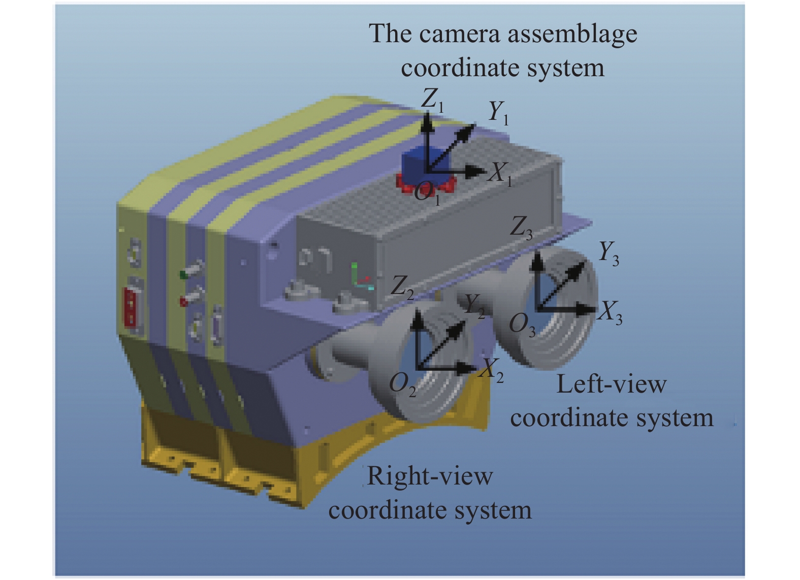
在双目视觉系统的结构上方安装有一个20 mm×20 mm×20 mm的立方镜,该立方镜即为系统的安装坐标系。其O1-X1Y1Z1定义如下:以立方镜体中心O1为坐标系原点,立方镜相邻的两个面的法线方向分别为X1轴、Y1轴,Z1轴由右手定则确定。右目相机坐标系O2-X2Y2Z2定义如下:相机的光心O2为坐标系的原点,坐标系的X2轴与相机光轴方向平行,Y2轴、Z2轴分别平行于相机成像面的水平轴、垂直轴。左目相机坐标系的定义与右目相同。图2为各坐标系定义图。

Figure 2. Definition of the coordinate system
-
双目视觉系统内外参标定技术主要解算的参数及精度要求如表1所示。
Parameter Specification Observation distance/m 0.3-1.3 Internal parameter Major point/pixel ≤±1 Major distance/pixel ≤±1 External parameter Position/mm ≤±0.5 Attitude/(°) ≤±0.1 Table 1. Calibration requirements of internal and external parameters of binocular vision system
-
在光束法平差法中使用的是经典的针孔模型,如图3所示,O-UV 为相机像平面坐标系,O1O为相机光轴,光轴与图像平面的交点O(u,v)为相机主点,光心O1到主点的距离为相机主距f。光线从物体所在空间出射,相机在不同方位拍摄多幅图像,利用各图像间匹配标志点的对应关系和内参不变特性,构建相机模型变换约束方程,整体解算像点坐标及主点、主距、畸变。
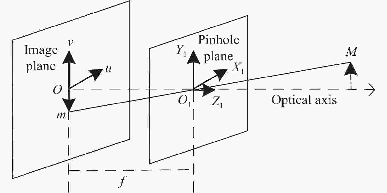
Figure 3. Principle of internal reference test
M(X,Y,Z)为物方一点,M在像平面的坐标为m(u,v,1),两者之间的映射关系为[6]:
式中:s为尺度因子;λ为比例系数;[r1,r2,t]为相机外参;A为相机内参矩阵,定义为:
式中:(u0,v0)为相机主点;
$\alpha $ 、β分别为相机水平和垂直方向的主距;γ为图像坐标轴的偏斜因子。文中采用使像点的重投影误差最小的优化方法来计算得到映射矩阵H [7],此时,优化目标函数为:
式中:
${\hat m_i}$ 为通过公式(1)计算得到的重投影图像坐标;${m_i}$ 为实际计算得到的图像坐标。令
$B = {A^{ - \rm{T}}}{A^{ - 1}} = \left[ {\begin{array}{*{20}{c}} {{B_{11}}}&{{B_{12}}}&{{B_{13}}} \\ {{B_{21}}}&{{B_{22}}}&{{B_{23}}} \\ {{B_{31}}}&{{B_{32}}}&{{B_{33}}} \end{array}} \right]$ ,将公式(2)代入,得到:用六维矢量b来表示对称矩阵B,即b=[B11 B12 B22 B31 B32 B33 ],因此,至少需要六个方程才能求解b。移动相机至不同位置对三维靶标场拍照,可以得到n(n≥3)幅图像,对应得到2n个方程,利用重投影误差最小优化可求解相机的内参矩阵A,进而得到相机内参,即:
-
内参标定时,双目视觉系统同时对三维靶标场目标进行拍照,再分别对左目相机和右目相机的图像进行处理进而得到两个相机的内参,以右目相机为例,其内参测试过程如下:
(1)相机拍摄多幅三维靶标场图像,求解靶标与相机图像间的映射矩阵;
(2)解算靶标与相机坐标系矩阵;
(3)构建相机内参约束方程;
(4)利用特征值分解,求解内参矩阵;
(5)解算焦距、主点坐标等参数,计算出内参最优解。
相机内参的测试精度用重投影误差来表示,该部分主要是模型算法引入的误差,通常情况下认为基于光束法平差算法的内参测试重投影误差小于0.5个像元。表2为该套系统的测试结果。
Camera Principal point/pixel Principal distance/mm Distortion coefficient Reprojection error/pixel Left-view [960.93,540.28] fx:1429.38
fy:1429.61k1:−0.0575
k2:0.1395
k3:0.0002
p1:−0.0002
p2:00.209 Right-view [957.20,540.52] fx:1424.01
fy:1424.34k1:−0.0547
k2:0.1343
k3:0.0006
p1:−0.0004
p2:00.207 Table 2. Calibration results of internal parameter of binocular vision system
-
外参即相机坐标系在系统安装坐标系中的位置和姿态,包括三个坐标参数(XS、YS、ZS)和三个角度参数(Rx、Ry、Rz)。测试时需要分别求出左目、右目相机坐标系与视觉系统安装坐标系的位姿关系,其标定过程如下:
(1)利用六自由度测站三维网平差法完成对相机安装坐标系的建立;
(2)利用经纬仪交会坐标测量方法得到三维靶标场与相机安装坐标系之间的位置关系;
(3)双目相机对三维靶标场成像,利用空间后方交会算法分别得到三维靶标场与左目、右目相机坐标系之间的位置关系;
(4)基于坐标转换原理,便可得到左目、右目相机坐标系与相机安装坐标系之间的位置关系。
-
双目视觉系统上安装的立方镜其表面中心刻有十字丝标志点,六个面十字丝的中心相交于立方镜的体心O1。文中采用徕卡T6100经纬仪建站的方式建立立方镜坐标系[8-10],测试示意图如图4所示。
测试步骤如下:
(1)选取经纬仪1作为基准,经纬仪2和经纬仪3分别与经纬仪1互瞄建立角度关系;
(2)三台经纬仪依次瞄准基准尺,建立位置关系;
(3)经纬仪1和经纬仪3瞄准相机立方镜Y向的十字丝,利用前方交会原理得到相机安装坐标系原点的空间位置;
(4)经纬仪1和经纬仪2分别自准直相机立方镜的-Y向和+X向,得到相机安装坐标系的空间方向;
(5)根据以上测试数据利用六自由度测站三维网平差法解算出相机的安装坐标系。

Figure 4. Test of camera coordinate system of binocular vision system
-
在三维靶标场上选取合适的四个点,任意选取图5中的两台经纬仪组成空间交会测量系统,通过经纬仪互瞄、测量基准尺和定向解算能够实现测量系统的定向,然后利用角度前方交会的原理,可得到靶标场上任意一个点在系统安装坐标系即立方镜下的三维坐标值,测量结果见表3。

Figure 5. Establish the relationship of the 3D target coordinate system and the camera assemblage coordinate system
Coordination/mm Point 1 Point 2 Point 3 Point 4 X 331.699 414.358 415.285 332.469 Y 202.393 −132.469 −136.654 198.190 Z 161.731 166.235 −163.688 −168.168 Table 3. Coordination of points in the cubic assemblage coordinate system
-
文中采用基于四个非共线控制点的单张相片空间后方交会算法来建立三维靶标场与双目相机的关系,如图6所示。
$O - XYZ$ 为物空间坐标系,$S - xyz$ 为像空间坐标系,$A({X_1},{Y_1},{Z_1})$ 、$B({X_2},{Y_2},{Z_2})$ 、$C({X_3},{Y_3},{Z_3})$ 为三个控制点,$A'({x_1},{y_1})$ 、$B'({x_2},{y_2})$ 、$C'({x_3},{y_3})$ 分别为对应的像点。
Figure 6. Translate of coordinate system
在
$\Delta ASB$ 、$\Delta BSC$ 、$\Delta ASC$ 中,由余弦定理可得:式中:
$\alpha $ 、$\;\beta $ 、$\gamma $ 可在$\Delta A'SB'$ 、$\Delta B'SC'$ 、$\Delta A'SC'$ 中由余弦定理获得。设${d_{AS}}$ :${d_{BS}}$ :${d_{CS}}$ =$1:n:m$ ,代入公式(6),可得:消去
${d_{AS}}$ 、m得到n的一元四次方程:式中:
${w_1}\sim{w_5}$ 为系数,求解该式可得至多四个n值。再加入一个控制点D,利用A、B、D三点求得另一组n值,选取两组中相同的一个即为实际距离比值。将其代入公式(7)可求得距离值${d_{AS}}$ 、${d_{BS}}$ 、${d_{CS}}$ 。在像空间坐标系
$S - xy{\textit{z}}$ 中,像点$A'$ 、$B'$ 、$C'$ 坐标分别为:$A'({x_1},{y_1}, - f)$ 、$B'({x_2},{y_2}, - f)$ 、$C'({x_3},{y_3}, - f)$ 。由比值${{{d_{A'S}}} \mathord{\left/ {\vphantom {{{d_{A'S}}} {{d_{AS}}}}} \right. } {{d_{AS}}}}$ 、${{{d_{B'S}}} \mathord{\left/ {\vphantom {{{d_{B'S}}} {{d_{BS}}}}} \right. } {{d_{BS}}}}$ 、${{{d_{C'S}}} \mathord{\left/ {\vphantom {{{d_{C'S}}} {{d_{CS}}}}} \right. } {{d_{CS}}}}$ 可得A、B、C在像空间坐标系中坐标$({X_{is}},{Y_{is}},{Z_{is}}){\rm{ }}(i = 1,2,3)$ 分别为:基于四个控制点的定向方法对控制点分布的要求是选取的四个点不共线,这四个控制点即为3.2章节选取的四个控制点。测试时,双目相机对三维靶标场进行拍照,分别求解得到三维靶标场上四个点在左目、右目相机坐标系中的坐标数值,结果见表4、表5。
Coordination/mm Point 1 Point 2 Point 3 Point 4 X 331.281 413.800 415.000 332.427 Y 152.116 −182.880 −186.300 148.130 Z 241.985 246.255 −83.678 −88.186 Table 4. Coordination of points in the left-view camera coordinate system
Coordination/mm Point 1 Point 2 Point 3 Point 4 X 331.286 413.805 415.101 332.423 Y 252.853 −82.055 −86.186 248.703 Z 241.731 246.258 −83.675 −88.178 Table 5. Coordination of points in the right-view camera coordinate system
-
设在系统安装坐标系O1-X1Y1Z1下公共点三维坐标参数为(X,Y,Z),右目相机坐标系O2-X2Y2Z2下的公共点三维坐标参数为(X′,Y′,Z′),如图7所示。

Figure 7. Principle of spatial rear intersection based on three control points
假设相机安装坐标系O1-X1Y1Z1先平移(X0,Y0,Z0),再旋转(εx,εy,εz),最后缩放k倍后,即可转换到右目相机坐标系O2-X2Y2Z2下,则相机坐标系下的点在相机安装坐标系下的计算公式如(10)所示:
式中:T为平移矢量R为旋转矩阵。当定向点个数大于等于3时,利用最小二乘法迭代计算,可求出相机安装坐标系和相机坐标系的转换参数[11-15]。
将表3~表5的数据按上述公式进行解算,即可得到双目视觉系统的外参,结果如表6所示。
Camera Rotation angle Translation vector εx εy εz ΔX ΔY ΔZ Left
view0.058 359.936 359.976 −0.341 −49.941 79.621 Right
view0.010 359.936 359.977 −0.313 50.616 79.584 Table 6. External parameters of the binocular vision system
-
外参测试需要将相机坐标系引入到系统安装坐标系下,包括空间向量与坐标系角度的转换。其中系统的各个环节误差组成如下,其精度均为3σ精度:
-
该项误差主要包括:
(1)经纬仪建站误差:根据大量的测试经验,该项误差在5 m测量范围内可以小于±0.05 mm;
(2)经纬仪交会测量误差:测试时在软件中将交会误差设置在±0.05 mm以下,超过该范围的点重新测量直到满足要求为止。
因此
${m_1} = \pm \sqrt {{{0.05}^2} + {{0.05}^2}} = \pm 0.07\;{\rm{ mm}}$ 。 -
系统安装坐标系即立方镜坐标系位置误差主要包括立方镜边长测量误差、十字丝刻划位置精准度、十字丝点坐标测试误差、立方镜不垂直误差四项误差。
(1)在目前的制造工艺下,立方镜边长测量误差可以控制在1 μm以内,立方镜不垂直误差可控制在1″以内,因此这两项可以忽略;
(2)立方镜十字丝刻划位置精准度,根据目前的制造工艺,该部分误差可以控制在±0.05 mm;
(3)十字丝点坐标测量误差为±0.05 mm。
因此该部分误差为:
-
该项误差主要包括经纬仪交会坐标测量误差和坐标系转换算法带来的误差。
(1)根据误差m1可知,经纬仪交会坐标测量误差为±0.05 mm;
(2)坐标系转换是利用一组公共点,通过其在不同坐标系下的坐标值进行最小二乘平差转换。根据计算,其转换误差为±0.06 mm。
在外参测试中,一共用到两次坐标系转换。
因此,该部分误差为:
综上所述系统总的测试误差为
$\delta = \pm \sqrt {{m_1}^2 + {m_2}^2 + {m_3}^2} = $ $ \pm 0.19 \;{\rm{mm}}$ 。 -
机械臂双目测量系统通过对目标特征图案的提取,能够实时对估算出测量目标的三维位置姿态等信息,相机内外参数的标定将直接影响其测量精度。文中基于光束法平差算法计算双目视觉系统的内参,并通过与经纬仪建站相结合的方法分别得到左目、右目相机的外参,实验表明,内参测试精度优于0.5个像元,外参测试精度优于±0.19 mm,测试精度高且操作简单,为机械臂实施视觉闭环自主捕获合作目标提供了可靠依据。


 DownLoad: