


-
涡旋光等相位面呈螺旋状,在传播过程中其中心相位具有不确定的点,常称为相位奇点,使得光束中心位置的强度分布为零[1]。这些特性使得涡旋光在光学操纵[2]、高分辨率显微成像[3]、光通信[4]、量子通信[5]以及光学测量[6]领域都有广泛应用。常用于产生涡旋光束的方法有:几何模式转换法[7]、计算全息法[8]、中空波导法、螺旋相位板法[9]、空间光调制器法[10]和特殊设计的激光器等。其中,最为常用的是螺旋相位板法和空间光调制器法。空间光调制器法具有产生方式简单、输出速度快、衍射效率高等优势,同时编码相息图可实现滤波,光束输出动态可控[11],因此研究中使用空间光调制器产生涡旋光更具优势。
光学测量技术以其高精度的光学标准尺度在纳米微位移测量研究中具有重要地位。比较典型的光学测量方法有[12]:X光干涉仪法,各种形式的激光干涉仪,光学光栅法等。其中,马赫泽德干涉仪测试原理简单、噪声小,通过灵活改进光路可以实现特定测量[13]。目前,研究者使用涡旋光用于光干涉仪测量的研究相对较少,研究多集中于涡旋光在通信领域自由通信的传播、光场中涡旋光螺旋相位的调控作用及涡旋光束自身特性和经过光学器件后的变化等研究[14-16]。而B Sokolenko等人在2017年使用相移技术与轮廓测量相结合,研究了涡旋相移对二维和三维形貌测量的影响[17]。2018年,Youngbin Na等人基于空间光调制器产生的涡旋光设计了更为稳定的干涉仪,并测定了透明物体的反射率[18]。这些研究显示,在基于涡旋光束的各种特性基础上,将涡旋光应在测量领域有重要的物理意义和巨大的应用前景。
文中基于涡旋光与球面波干涉条纹呈螺旋状分布的特性[19],提出一种物体微位移的光学测量方法。采用改进的马赫泽德干涉光路结构,使用空间光调制器产生涡旋光作为参考光束,与照射物体后的球面波干涉,通过测量涡旋光与球面波干涉螺旋条纹的旋转角度,从而测量物体变化的位移量。通过使用光学数值分析软件VirtualLab Fusion仿真分析和实验测量,结果显示该方法能够实时监测物体位移量的变化,并通过图像处理获得准确的位移值。
-
纯相位液晶空间光调制器(Liquid Crystal Spatial Light Modulator,LC SLM)作为实时光学信息处理器件,能够快速、准确地产生所需要的涡旋光束。由纯相位空间光调制产生的拉盖尔-高斯涡旋光束沿z轴传输的光场表达式为[20]:
式中:
$p$ 为强度分布的径向节点数;$l$ 为拓扑荷数;$z$ 为传输距离;$r$ 为柱坐标下的径向分量;$w(z) = {w_0}\sqrt {1 + {{\left( {{z/{{z_R}}}} \right)}^2}} $ 为拉盖尔-高斯涡旋光束在z处的束腰半径;${\omega _0}$ 为高斯光束的束腰半径;${z_R} = {{{\rm{\pi }}w_0^2}/{\rm{\lambda }}}$ 为瑞利距离;$L_p^{\left| l \right|}\left( . \right)$ 为归一化的拉盖尔多项式;$\theta $ 表示涡旋光的方位角;$k = 2{\rm{\pi }}/\lambda $ 是波数;${\rm{\lambda }}$ 为光波波长;根据参考文献[21],简化后的涡旋光的电场表达式为:
理想情况下,球面波的电场表达式为[22]:
式中:A表示球面波的振幅;
$\dfrac{{{r^2}}}{{2z}}$ 为球面波带来的相位;z为传输距离。两束光叠加干涉的复振幅为:
为了简化计算,假设在探测面上两束光的光强相同,即
${E_0} = {{A}} = \left( {\dfrac{{r\sqrt 2 }}{{{\omega _0}}}} \right)$ ,则干涉叠加时光强为:当测量物体产生微位移时,干涉光强相位变化
$\Delta \varphi $ ,此时干涉光强表达式变为:由公式(6)可知,当拓扑荷数l=1时,光强度中心旋转角度与干涉条纹螺旋相位的旋转角度一致,因此可以通过测量干涉螺旋条纹的旋转角确定相位的变化。根据相位与位移的关系,位移量可表示为:
式中:d表示位移量;
$\Delta \varphi $ 为位移产生的涡旋光与球面波干涉相位变化。 -
VirtualLab Fusion光学设计软件由德国LightTrans公司研发的一款物理光学数值分析软件,是涵盖几何光学和波动光学的统一光学建模平台[23]。通过图形化的交互接口可以任意设计光学流程图,实现自定义数值仿真。VirtualLab Fusion通过求解麦克斯韦方程组,可以在整个光学系统空间中获得光波场向量信息,在确保所有模式光源与通过光学元件任意传输方法的情况下,获得准确的仿真结果。
如图1所示,基于涡旋光与球面波干涉理论测量物体微位移的光学建模流程图。图中“Gaussian wave”为高斯光束(632.8 nm),光束直径为0.7 mm;“Ideal lens1” 、“Ideal lens2”为理想透镜,实现光束扩束,焦距分别为f1=2 mm,f2=20 mm;“Ideal beam spliter”为分束器,分光比为50:50;“LC SLM”为自定义的空间光调制器,拓扑荷数设置为+1;“Spherical phase”为球面相位,将高斯光束变为球面波;“Ideal plane mirror1”、“Ideal plane mirror2”为理想平面镜,理想平面镜2用于产生微小位移;“Raw data detector”为探测器,记录干涉图像。设置光路的参数,光源与理想棱镜1的距离设置为2 mm,理想棱镜1与理想棱镜2的距离设置为22 mm,分光棱镜与理想棱镜2的距离设置为2 mm,LC SLM与球面相位均距离分光棱镜2 mm,为了便于实现纳米位移,理想平面镜1和理想平面镜2与前一个元件的距离均设置为0,探测器距离理想平面镜1与理想平面镜2均设置为2 mm。

Figure 1. Simulation flow chart of measuring micro-displacement based on the theory of vortex beams and spherical wave interference
-
实验结果如图2所示,改变理想平面镜2的位置参数,获得位移前后的涡旋光与球面波的干涉图像,图2(a)为物体位移前的干涉条纹,图2(b)、(c)、(d)为物体位移后的干涉条纹。从图中可以看到涡旋光与球面波的干涉条纹是螺旋形状,当物体发生位移,整个螺旋条纹相比于位移前,发生角度的旋转,经过图像处理可得到旋转角度变化量为位移变化导致的相位变化量。仿真中,为了计算方便,位移d变化量分别为52.73 、237.30 和316.40 nm,对应于相位变化为
${30^ \circ }$ 、${135^ \circ }$ 和${180^ \circ }$ 。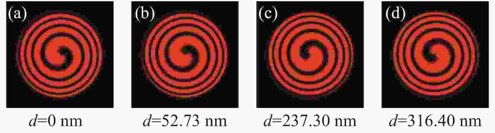
Figure 2. Interference intensity of vortex beams and spherical wave before and after micro-displacement in the simulation
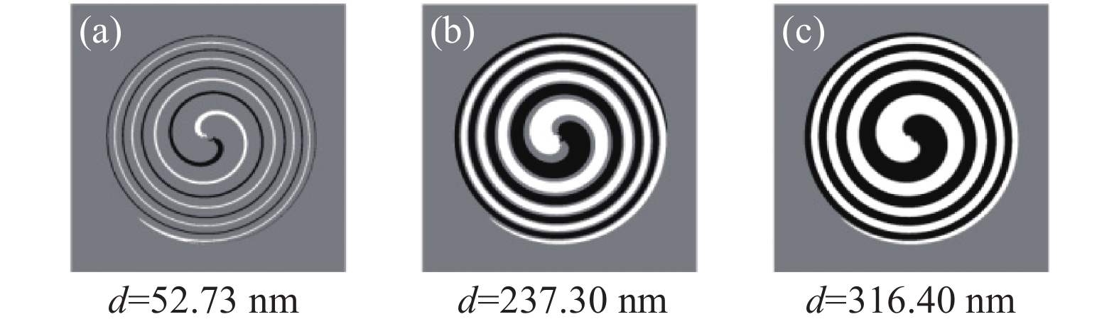
将仿真图像使用matlab进行图像处理,获得相对应的位移量。将位移前后的两幅图二值化处理后,使用位移后的图像减去位移前的图像,得到如图3(a)、(b)、(c)所示的位移前后干涉图相减强度分布图,将明暗两个旋转起点中心位置确定为旋转中心,当如图3(c)中相间条纹,不易分辨中心时,则通过相加模式,将位移前和位移后两幅图的强度相加,由于灰度显示不同,相加后可以看出明暗两个旋转起点中心位置,从而确定旋转中心。两种模式都是基于对称性确定旋转中心。以旋转中心为定点绘制干涉螺旋条纹的起始光斑处的中心切线,得到位移前后两幅干涉螺旋条纹的中心切线,分别如图4(a)、(b)、(c)、(d)所示,根据位移前后两图的切线位置,计算切线的角度即为物体位移前后旋转角度,进一步计算得到物体位移量。通过图像处理仿真位移前后两幅图后得到的结果如表1所示,仿真结果说明基于涡旋光与球面波干涉螺旋条纹旋转角度的变化可以有效计算物体的微位移。
Displacement of theory/nm 52.73 237.30 316.40 Rotation angle of theory/(°) 30 135 180 Rotation angle of simulation/(°) 30.79 136.39 180 Displacement of calculation/nm 54.12 239.74 316.40 Error/nm 1.37 2.44 0 Table 1. Measurement results of simulation

Figure 3. Subtractive intensity distribution of the interferogram before and after the micro-displacement of the object in the simulation

Figure 4. Tangent line of the spiral fringe before and after micro-displacement of object in the simulation
-
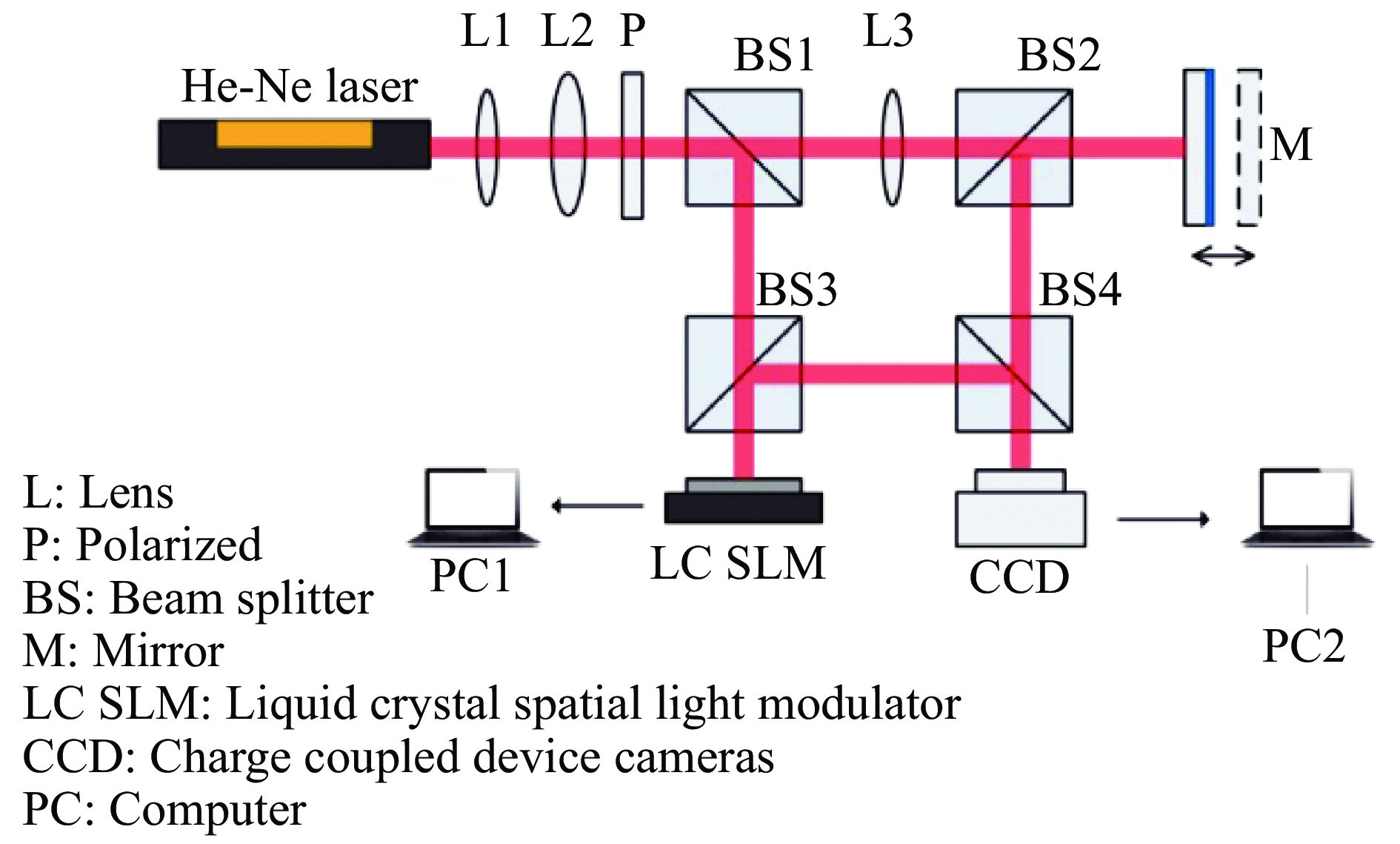
采用空间光调制器产生的涡旋光束,利用改进的马赫泽德干涉仪对压电陶瓷产生的微位移进行测量,实验装置示意图如图5所示。光源为偏振He-Ne激光器(632.8 nm、2 mW),经过透镜L1(f1=50 mm)、L2(f2=300 mm)进行扩束,扩束后的光束通过偏振器P,经分光棱镜BS1分为两束光,其中一束光通过透镜L3(f3=150 mm)后变为球面波,之后透过分光棱镜BS2照射在与压电陶瓷相连的标准反射镜面M,反射镜反射后光束再由分光棱镜BS2反射后到达分光棱镜BS4;另一束光透过分光棱镜BS3照射在液晶空间光调制器LC SLM上,产生涡旋光束到达分光棱镜BS3,再由分光棱镜BS3反射后到达分光棱镜BS4。两束光在分光棱镜BS4合束后,发生干涉,成像在CCD光敏面上,记录下位移前后的干涉图像。偏振片P的作用是匹配反射式液晶空间光调制(空间光调制器仅对竖直方向偏振有作用)。实验中的LC SLM为德国holoeye反射式纯相位液晶空间光调制器PLUTO-NIR-011,其分辨率为1 920×1 080,像素单元尺寸为8.0 μm,响应时间16~200 ms。相机使用的是lumenera Lm165,像素为1 040×1 392,像数单位尺寸为6.45 μm。

Figure 5. Experimental set up for measuring micro-displacement of objects based on vortex beams and spherical wave interferometry
-
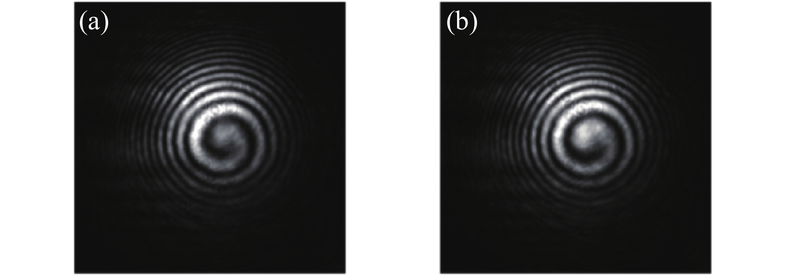
实验结果如图6所示。实验过程中压电陶瓷的位移为27 nm,由于光路往返,系统产生的实际位移为54 nm。如图6所示为压电陶瓷位移前后拍摄的两幅涡旋光与球面波干涉图像。图6(a)为压电陶瓷产生位移前的干涉图样,图6(b)为压电陶瓷产生位移后的干涉图样。图中可以明显看到实验中涡旋光与球面波的干涉与仿真一致,呈螺旋状分布,压电陶瓷产生微位移后,干涉螺旋条纹发生了明显的旋转。

Figure 6. Interference fringes of vortex and spherical waves in the experiment. (a) Interference pattern before the displacement of the piezoelectric ceramics , (b) Interference pattern after the displacement of the piezoelectric ceramics
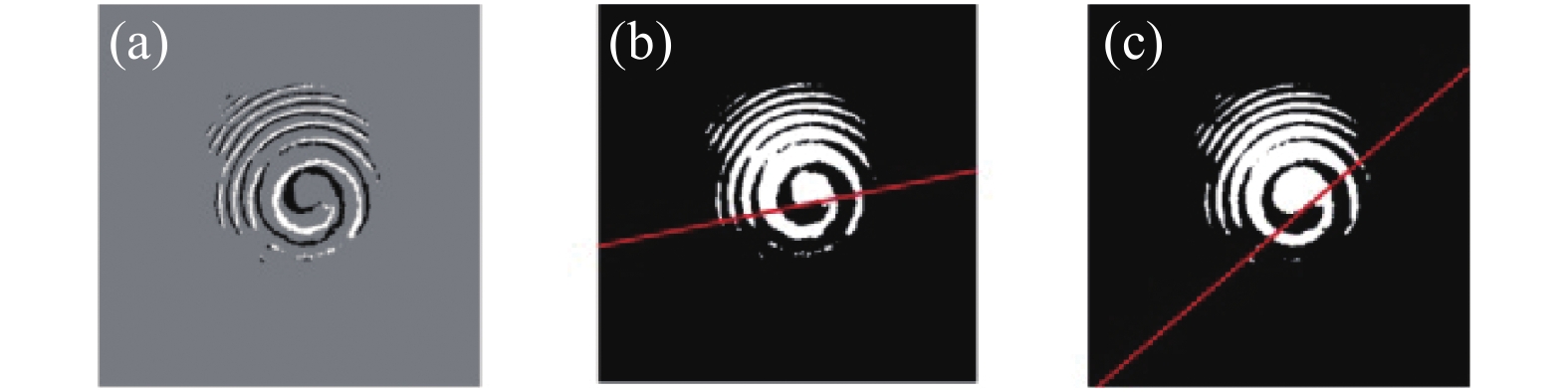
将实验获得的两幅图像与仿真图像做相同的处理,如图7(a)所示为实验干涉条纹二值化后位移前后两幅图相减强度分布图,确定中心后绘制如图7(b)、(c)所示的仿真位移前螺旋条纹中心切线和位移后螺旋条纹的中心切线。处理压电陶瓷位移前后的两图干涉图得到螺旋条纹的旋转角度为29.29°,计算后位移变化量为51.49 nm,对于压电陶瓷的位移为25.75 nm,误差为1.25 nm。

Figure 7. MATLAB processing results of experimental image. (a) Subtractive intensity distribution of the interferogram before and after the micro-displacement, (b) Tangent of the spiral fringe before the micro-displacement, (c) Tangent of the spiral fringe after the micro-displacement
-
文中在分析涡旋光与球面波的干涉理论的基础上,提出一种物体微位移的光学测量方法。涡旋光作为参考光束与照射物体后的球面波干涉,由于涡旋光与球面波干涉条纹呈螺旋状分布,当物体表面发生微小位移时,干涉螺旋条纹发生旋转。通过图像处理比较物体位移前后该螺旋条纹的旋转角度变化,即可计算出物体的位移变化。文中分别利用Virtuallab仿真与搭建实验系统验证均表明,基于涡旋光与球面波干涉螺旋条纹旋转角度的变化可以有效计算物体的微位移。当测量物体的位移量为27 nm,系统位移为54 nm时,涡旋光与球面波干涉的螺旋条纹实际旋转29.29°,计算后位移变化量为51.49 nm,对于物体的位移为25.75 nm,误差为1.25 nm。该方法可用于实时简洁方便、快速直观的监测物体微小位移变化。
Measurement of micro-displacement based on the interference of vortex beams and spherical wave
doi: 10.3788/IRLA202049.0413005
- Received Date: 2019-12-06
- Rev Recd Date: 2020-01-26
- Accepted Date: 2020-02-25
- Publish Date: 2020-04-24
-
Key words:
- vortex beam /
- micrometric displacement /
- spiral phase /
- spatial light modulator
Abstract: Based on the theory of vortex beams and spherical wave interference, an optical measurement method for object micro-displacement was proposed. After improving the Mach-Zehnder interference optical path, a vortex beam was generated as a reference beam, using the spatial light modulator illuminated by a beam of light, and another beam was transformed into a spherical wave through the lens and illuminated to the object. The interference fringes were distributed in a spiral shape as the two beams interfered. When the object has a micro-displacement, the optical path difference of the two beams changes, and the spiral interference fringe rotates. Noticing this phenomenon, the micro-displacement of the object can be determined by the rotation angle of the spiral interference which vortex beams interference with spherical wave. Through theoretical analysis, simulation and experiments have proved that the micro-displacement of the object can be monitored in real time, and effectively calculated by the rotation angle change of spiral fringe based on interference of vortex beams and spherical wave. In the experiment, the displacement of the measured object is 27 nm, the actual measured displacement of the object is 25.75 nm, and the error is 1.25 nm compared with the theoretical value.


 DownLoad: